WARNING:
•Risk of electric shock
•Use extreme caution to avoid electrical shock. Serious injury or death could result.
• Always disconnect power from the safety system (for example, device, module, interfacing, etc.),
guarded machine, and/or the machine being controlled before making any connections or
replacing any component. Lockout/tagout procedures might be required. Refer to OSHA
29CFR1910.147, ANSI Z244-1, or the applicable standard for controlling hazardous energy.
• Make no more connections to the device or system than are described in this manual. Electrical
installation and wiring must be made by a Qualified Person 2and must comply with the applicable
electrical standards and wiring codes, such as the NEC (National Electrical Code), NFPA 79, or
IEC 60204-1, and all applicable local standards and codes.
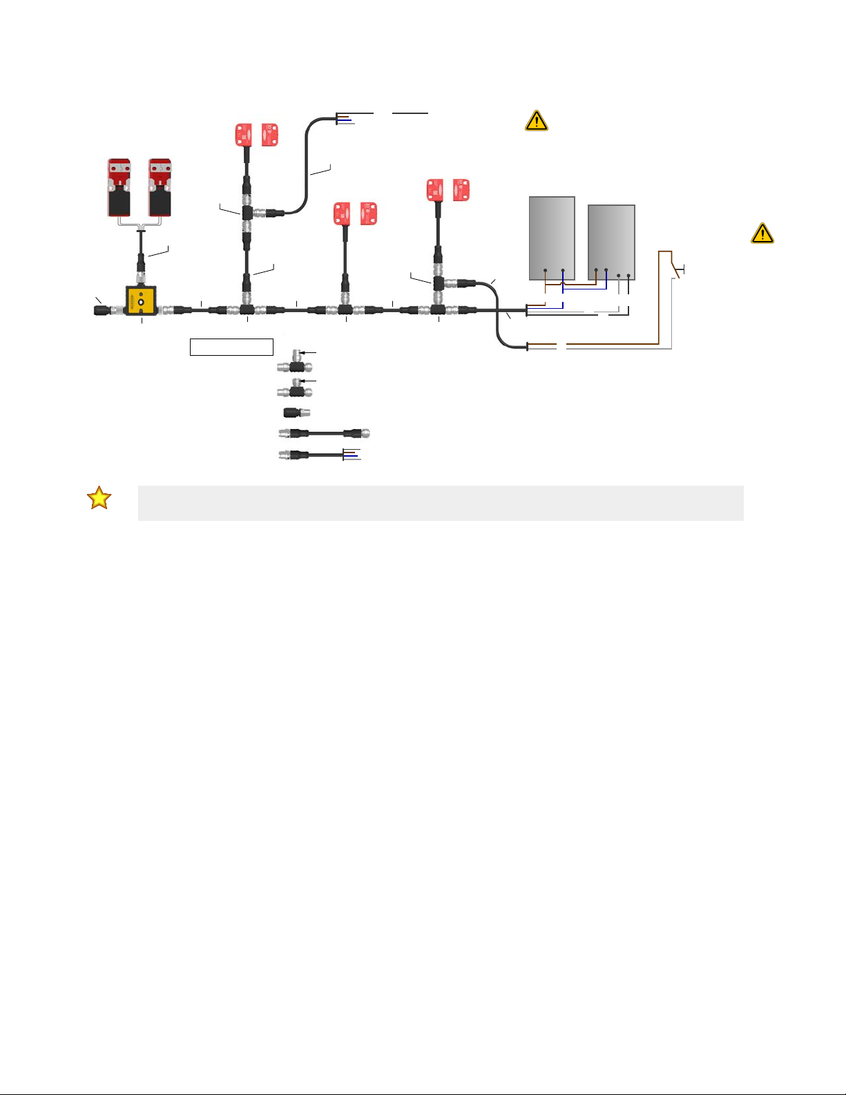
2.3 Protective (Safety) Stop Circuits
A protective (safety) stop allows for an orderly cessation of motion for safeguarding purposes, which results in a stop of
motion and removal of power from the Machine Primary Control Elements (MPCE) (assuming this does not create additional
hazards).
A protective stop circuit typically comprises a minimum of two normally open contacts from forced-guided, mechanically
linked relays, which are monitored through External Device Monitoring (EDM) to detect certain failures, to prevent the loss of
the safety function. Such a circuit can be described as a "safe switching point".
Protective stop circuits are either single channel, which is a series connection of at least two normally open contacts, or
dual-channel, which is a separate connection of two normally open contacts. In either method, the safety function relies on
the use of redundant contacts to control a single hazard. If one contact fails On, the second contact arrests the hazards and
prevents the next cycle from occurring.
Interface the protective stop circuits so that the safety function cannot be suspended, overridden, or defeated, unless
accomplished in a manner of the same or greater degree of safety as the machine's safety related control system that
includes the SSA-ISD Connect.
An ISD compatible Banner Safety Controller, such as the SC10-2ro, provides a series connection of redundant contacts
that form protective stop circuits for use in either single-channel or dual-channel control.
2.4 Output Signal Switching Devices (OSSDs) and External Device
Monitoring (EDM)
The SSA-ISD Connect is able to detect faults on OSSD1 and OSSD2. These faults include short circuits to +24 V DC and 0
V, and between OSSD1 and OSSD2.
Both OSSD outputs must be connected to the machine control so that the machine's safety-related control system
interrupts the circuit or power to the machine primary control element(s) (MPCE), resulting in a non-hazardous condition.
Final switching devices (FSDs) typically accomplish this when the OSSDs go to an OFF state.
Refer to the output specifications and these warnings before making OSSD output connections and interfacing the SSA-ISD
Connect to the machine.
WARNING:
•Interfacing both output signal switching devices (OSSD)
•Failure to follow these instructions could result in serious injury or death.
• Unless the same degree of safety is maintained, never wire an intermediate device(s) (PLC, PES,
PC) between the safety module outputs and the master stop control element it switches such
that a failure causes a loss of the safety stop command or the failure allows the safety function to
be suspended, overridden, or defeated.
• Connect both OSSD outputs to the machine control so that the machine’s safety-related control
system interrupts the circuit to the machine primary control element(s), resulting in a non-
hazardous condition.
2A person who, by possession of a recognized degree or certificate of professional training, or who, by extensive knowledge, training and
experience, has successfully demonstrated the ability to solve problems relating to the subject matter and work.
SSA-ISD Connect with Indication
www.bannerengineering.com - Tel: + 1 888 373 6767 5