c. Remote control
Set remote control function.
On: Remote control is permitted.
Off: Remote control is forbidden.
In “System Setting” interface, press and then turn the
to enter “c. Remote Control” interface. Press the
to enter remote control selection interface. Turn the
to select the remote control state. Press the
to save and return back to “c. Remote Control”
interface.
Adjusting
Knob Adjusting
Knob
Adjusting Knob
Adjusting Knob
d.Pump I.D.
When control computer controls many pumps through RS485
interface, it must identify each pump's I.D.. This pump I.D. should
be unique. It's the identification of this pump.
In “System Setting” interface, press and then turn the
to enter “d. Pump I.D.” interface. Press the
to enter pump I.D. setting interface. Turn the
to set the pump I.D. # (1 -30). Press the
to save and return back to “d. Pump I.D.” interface.
Adjusting
Knob Adjusting
Knob Adjusting
Knob Adjusting Knob
Remote Control
On Off
↑
Set ump I.D.#.P
1
↑
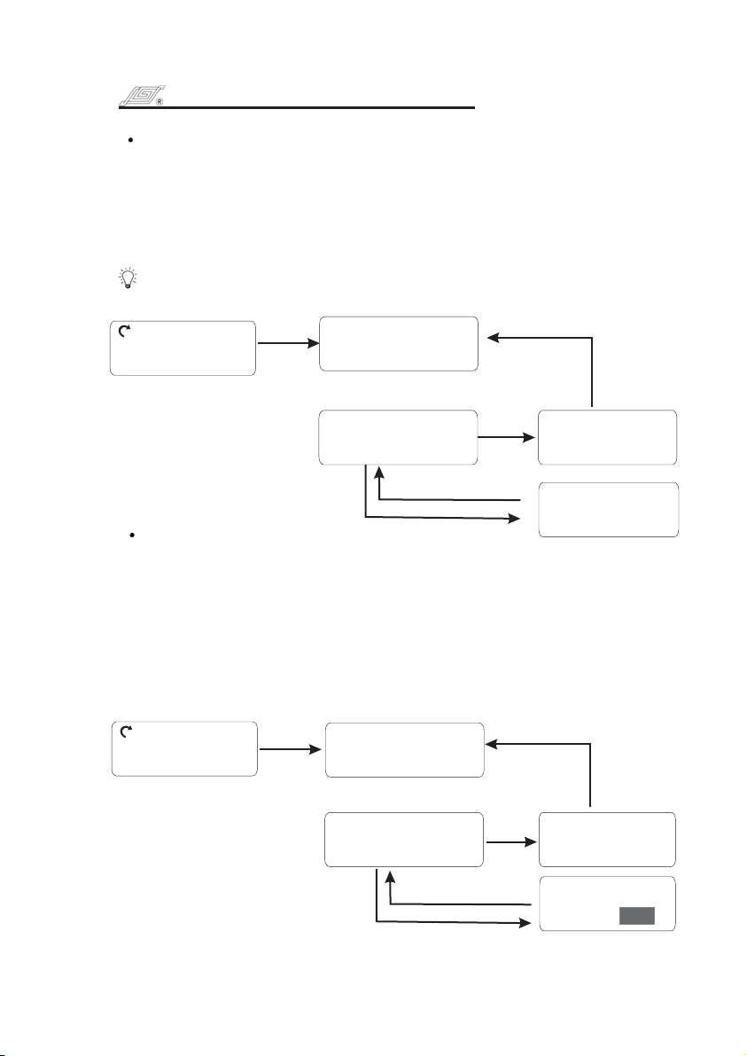
b. Test time
The test time is the required time for one time flow rate
calibration.
In “System Setting” interface, press and then turn the
to enter “b. Test time” interface. Press the
to enter “Set test time” interface. Turn the to set
the test time. Press the to save and return back
to “b. Test time” interface.
Note: The time range is 0.5 25 min. The increment is 0.5 min.
Adjusting
Knob Adjusting Knob
Adjusting Knob
Adjusting Knob
Set test time:
0.5 min
↑
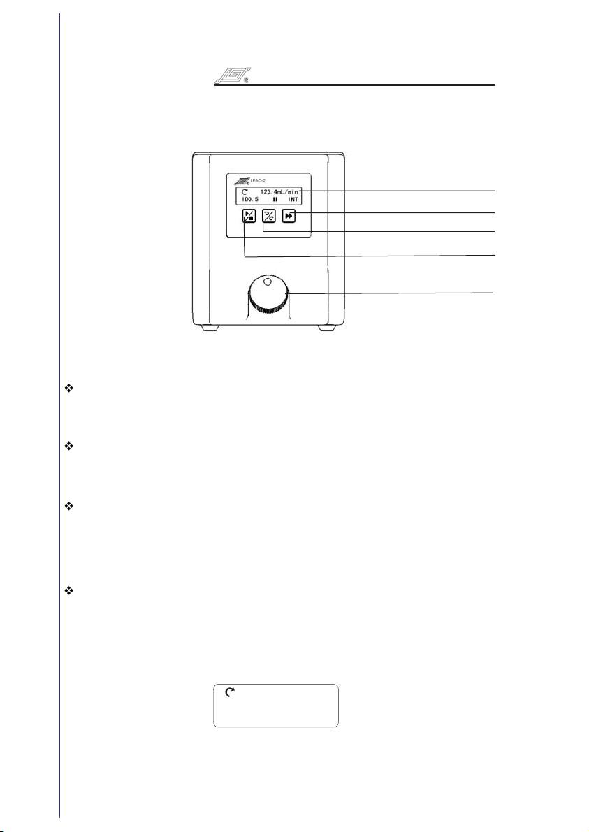
ID 0.5 INT■
123.4mL/min
ID 0.5 INT■
123.4mL/min
ID 0.5 INT■
123.4mL/min
e. Footswitch
Set footswitch working mode.
In “System Setting” interface, press and then turn the
to enter “e. Footswitch” interface. Press the
to enter footswitch setting interface. Turn the
to select footswitch working mode. Press the
to save and return back to “e. Footswitch” interface.
Trigger: Press footswitch, the pump starts running; Press
footswitch again, the pump stops.
Gated: The pump runs as long as the footswitch is pressed.
Adjusting
Knob Adjusting
Knob Adjusting
Knob Adjusting
Knob
Footswitch
Gated Trigger
↑
ID 0.5 INT■
123.4mL/min
78
LEAD-2OPERATINGMANUAL LEAD-2OPERATINGMANUAL
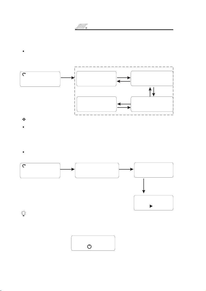
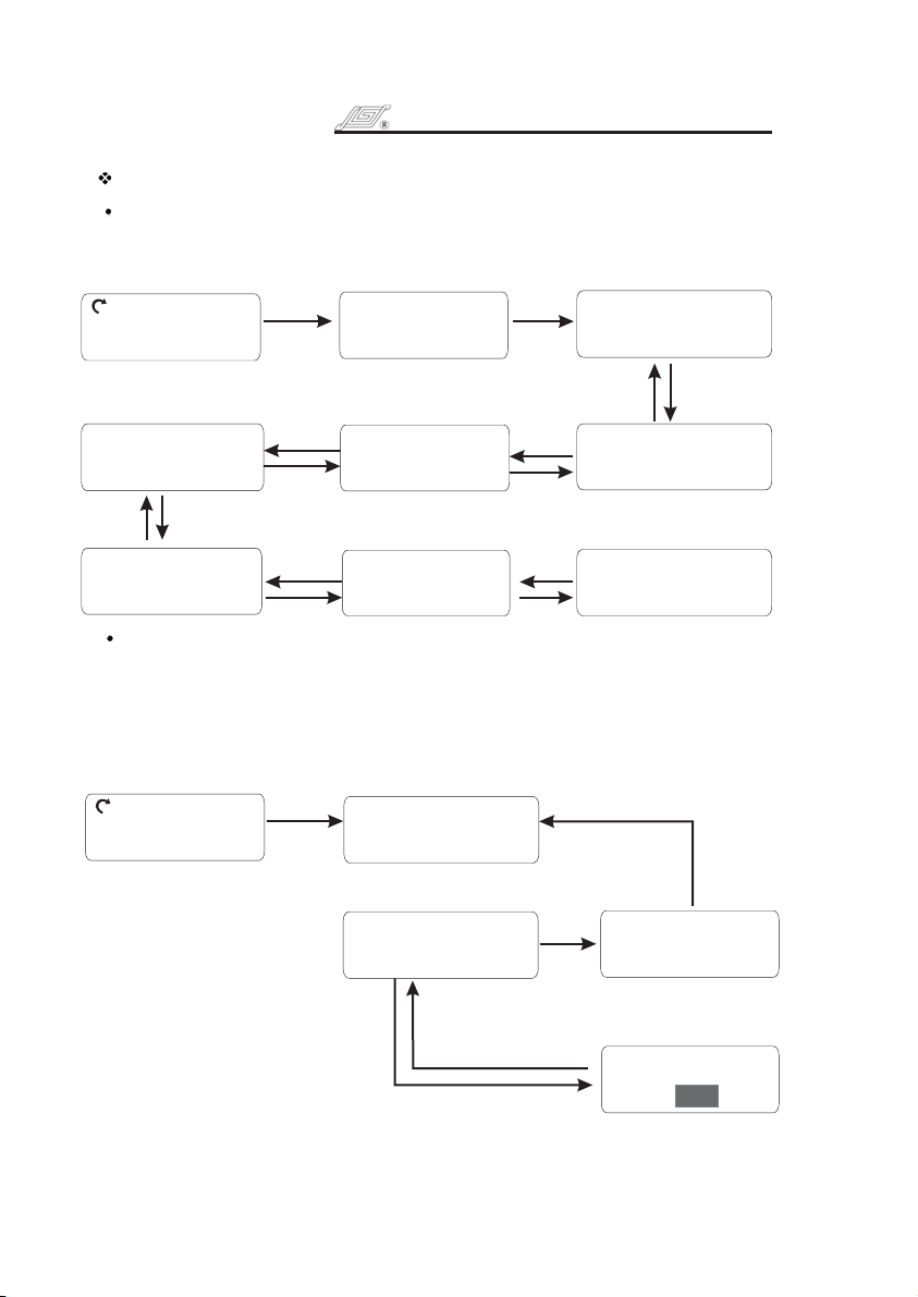
2. ystem SettingS
2. ystem SettingS
2. ystem SettingS
2. ystem SettingS
b.Test time
0.5min
:
f. ackB
f. ackBf. ackB
f. ackB
c.Remote
Control:on
d. ump I.D.#.P
1
e.Footswitch
Gated
:
Press
the Knob
Press the Knob
Press
the Knob
Press the Knob
Press
the Knob
Press the Knob
Press
the Knob
Press the Knob
Turn the
Knob
Turn the
Knob
Turn the
Knob
Turn the Knob to select
Turn the
Knob
TurntheKnobtoselect
Press the knob
andthenturn
the knob
Press the knob
andthenturn
the knob
Press the knob
and then turn
the knob
Press the knob
andthenturn
the knob
Press the knob
andthenturn
the knob
Press the knob
andthenturn
the knob
Press the knob
andthenturn
the knob
Press the knob
andthenturn
the knob
TurntheKnobtoselect
Running interface
To switch to “Speed Display”
please see page 9 “Control
Mode” for setting method
Running interface
To switch to “Speed Display”
please see page 9 “Control
Mode” for setting method
Running interface
To switch to “Speed Display”
please see page 9 “Control
Mode” for setting method
Running interface
To switch to “Speed Display”
please see page 9 “Control
Mode” for setting method
Turn the knob
To set the tim e