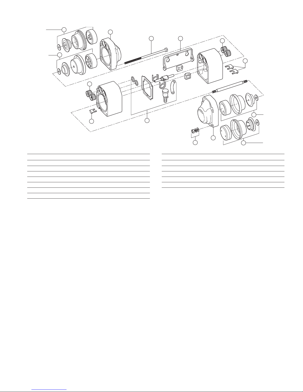
FLOJET N5100-010 Guide


This manual suits for next models
7
Other FLOJET Water Pump manuals

FLOJET
FLOJET N5000 Series Operation manual

FLOJET
FLOJET G-57 Series Installation instructions

FLOJET
FLOJET 03526-144 User manual

FLOJET
FLOJET 4300 Series User manual

FLOJET
FLOJET R4515-743 User manual

FLOJET
FLOJET 02840100A Operating and installation instructions

FLOJET
FLOJET 3426 series User manual

FLOJET
FLOJET 4305-144 User manual

FLOJET
FLOJET BevJet Compact User manual

FLOJET
FLOJET R3B21 Series User manual

FLOJET
FLOJET R3526144 User manual

FLOJET
FLOJET quad II diaphragm 4125 series User manual

FLOJET
FLOJET 4105 Series User manual

FLOJET
FLOJET G56 User manual

FLOJET
FLOJET N5100 Series Guide

FLOJET
FLOJET N5000 User manual

FLOJET
FLOJET G70C Series Owner's manual

FLOJET
FLOJET G257 Series Guide

FLOJET
FLOJET 2100-12 User manual

FLOJET
FLOJET 2125 Series User manual


Popular Water Pump manuals by other brands

Grundfos
Grundfos PS.G Series Installation and operating instructions

Becker
Becker SV 5.250 operating instructions

KNF
KNF NF 25 Series Operating and installation instructions

Barnes
Barnes 3SE-DS Series Installation and operation manual

BOC Edwards
BOC Edwards E1M175S instruction manual

Wheaton
Wheaton OmniSpense ELITE Series instruction manual

Franklin Pump Systems
Franklin Pump Systems DDD Series owner's manual

BUSCH
BUSCH DOLPHIN LG 0890 A instruction manual

Pentair
Pentair SHURFLO 802 Series Installation and operation manual

Xylem
Xylem Bell & Gossett e-80SCXL Series instruction manual

GORMAN-RUPP PUMPS
GORMAN-RUPP PUMPS PA Series Installation, operation and maintenance manual

WilTec
WilTec PW600 instruction manual


