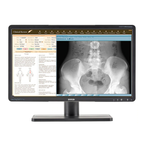
Barco Coronis Fusion 4MP User manual

Getting Started Guide
Nio Fusion 4MP

2
(This page intentionally left blank.)

3
Copyright notice
This document is copyrighted. All rights are reserved. Nor this
document, nor any part of it, may be reproduced or copied in any form
or by any means - graphical, electronic, or mechanical including
photocopying, taping or information storage and retrieval systems -
without written permission of Barco
© 2006 Barco N.V. All rights reserved.

Table of Contents
4
Table of Contents
Preface ....................................................................................... 5
Environmental information................................................................. 9
Safety Instructions............................................................................. 10
Explanation of symbols ..................................................................... 13
Introduction ............................................................................. 15
Display parts, controls and connectors............................................. 16
Front............................................................................................ 16
Rear............................................................................................. 17
Connectors .................................................................................. 19
Display installation .................................................................. 23
Installation precautions..................................................................... 24
Connecting the signal cables ............................................................ 25
Cable routing ..................................................................................... 28
Vesa-mount installation.................................................................... 29
Where to get more information .............................................. 31
Troubleshooting ....................................................................... 35
General tips........................................................................................ 36
Warranty Statement ................................................................ 41

5
Preface

Table of Contents
6
Notice
Although every attempt has been made to achieve technical accuracy in
this document, we assume no responsibility for errors that may be
found. Our goal is to provide you with the most accurate and usable
documentation possible; if you discover errors, please let us know.
BarcoView software products are the property of BarcoView. They are
distributed under copyright by Barco N.V. or BarcoView, LLC., for use only
under the specific terms of a software license agreement between
Barco N.V. or BarcoView LLC. and the licensee. No other use, duplication,
or disclosure of a BarcoView software product, in any form, is
authorized.
The specifications of BarcoView products are subject to change without
notice.
Trademarks
All trademarks and registered trademarks are property of their
respective owners.
FCC Compliance Information (display)
This device complies with Part 15 of the FCC Rules. Operation is subject
to the following two conditions: (1) this device may not cause harmful
interference, and (2) this device must accept any interference received,
including interference that may cause undesired operation.
NOTE: This equipment has been tested and found to comply with the
limits for a Class A digital device, pursuant to Part 15 of the FCC Rules.
These limits are designed to provide reasonable protection against
harmful interference in a residential installation. This equipment
generates, uses and can radiate radio frequency energy and, if not
installed and used in accordance with the instructions, may cause
harmful interference to radio communications. However, there is no
guarantee that interference will not occur in a particular installation. If
this equipment does cause harmful interference to radio or television
reception, which can be determined by turning the equipment off and
on, the user is encouraged to try to correct the interference by one or
more of the following measures:

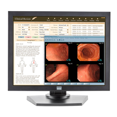
Table of Contents
7
• Reorient or relocate the receiving antenna.
• Increase the separation between the equipment and receiver.
• Connect the equipment into an outlet on a circuit different from
that to which the receiver is connected.
• Consult the dealer or an experienced radio/TV technician for
help.
Canadian notice
This Class A digital apparatus complies with Canadian ICES-003.
Cet appareil numérique de la Classe A est conforme à la norme NMB-
003 du Canada.
FCC Compliance Information (display controller)
CLASS B:
This Barco Graphics Controller complies with part 15 of the FCC rules.
Operation is subject to the following two conditions:
This equipment has been tested and found to comply with the limits for
a Class B digital device, pursuant to part 15 of the FCC rules. These limits
are designed to provide reasonable protection against harmful
interference in a residential installation. This equipment generates, uses
and can radiate radio frequency energy and, if not installed and used in
accordance with manufacturer’s instructions, may cause harmful
interference to radio communications. However, there is no guarantee
that interference will not occur in a particular installation. If this
equipment does cause harmful interference to radio or television
reception, which can be determined by turning the equipment off and
on, the user is encouraged to try to correct the interference by one or
more of the following measures:
• Re-orient or relocate the receiving antenna.
• Increase the separation between the equipment and receiver.
1. This device may not cause harmful interference, and
1. this device must accept any interference received, including
interference that may cause undesired operation.

Table of Contents
8
• Connect the equipment into an outlet on a circuit different from
that to which the receiver is connected.
• Consult the dealer or an experienced radio/TV technician for
help.
The use of shielded cables for connection of the monitor to the
graphics card is required to ensure compliance with FCC regula-
tions. Changes or modifications to this unit not expressly
approved by Barco could void the user’s authority to operate this
equipment.

Environmental information
9
Environmental information
Disposal Information
The lamps inside the display contain mercury. Do not throw the display
in the trash. Dispose of it as required by local ordinances or regulations.
This equipment has required the extraction and use of natural resources
for its production. It may contain hazardous substances for health and
environment.
In order to avoid the dissemination of those substances in the
environment and to diminish the pressure on natural resources, we
encourage you to use the appropriate take-back systems.
Those systems will reuse or recycle most of the materials of your end-
of-life equipment in a sound way.
The crossed-out wheeled bin symbol invites you to use those
systems.
If you need more information on the collection, reuse and
recycling systems, please contact your local or regional waste
administrator.
You can also contact us for more information on the environmental
performances of our products.

Safety Instructions
10
Safety Instructions
General Recommendations
Read the safety and operating instructions before operating the display.
Retain safety and operating instructions for future reference.
Adhere to all warnings on the display and in the operating instructions
manual.
Follow all instructions for operation and use.
Electrical shock
Type of protection (electrical):
Display with external power supply: Class III equipment
Degree of safety (flammable anesthetic mixture):
Equipment not suitable for use in the presence of a flammable
anesthetic mixture with air or with oxygen or nitrous oxide.
Non-patient care equipment
Equipment primarily for use in a health care facility that is intended for
use where contact with a patient is unlikely.
Power connection - display with external power supply
• Power requirements: The display must be powered using a
medical approved 24 VDC SELV power supply.
• The medical approved DC power supply must be powered by the
AC mains voltage.

Safety Instructions
11
Power cords:
• Utilize a UL-listed detachable power cord, 3-wire, type SJ or
equivalent, 18 AWG min., rated 300 V min., provided with a
hospital-grade type plug 5-15P configuration for 120V
application, or 6-15P for 240V application.
• Do not overload wall outlets and extension cords as this may
result in fire or electric shock.
• Mains lead protection (U.S.: Power cord): Power cords should be
routed so that they are not likely to be walked upon or pinched
by items placed upon or against them, paying particular
attention to cords at plugs and receptacles.
Water and moisture
Never expose the display to rain or moisture.
Never use the display near water - e.g. near a bathtub, washbasin,
swimming pool, kitchen sink, laundry tub or in a wet basement.
Ventilation
Do not cover or block the ventilation openings in the cover of the set.
When installing the display in a cupboard or another closed location,
heed the necessary space between the set and the sides of the
cupboard.
Installation
Place the display on a flat, solid and stable surface that can support the
weight of at least 3 displays. If you use an unstable cart or stand, the
display may fall, causing serious injury to a child or adult, and serious
damage to the equipment.
More warnings in the Installation chapter.

Safety Instructions
12
Operating precautions
Continuous operation of the display with the same image may result in
some image sticking on the LCD panel. Over 10 hours operation with the
same image content is not recommended.
Switching on DPMS on display and PC and activating a good screen saver
may decrease the risk of image sticking (image retention).
This apparatus conforms to:
CE (LVD 73/23/EEC), IEC 60950-1, UL 60950-1,
CAN/CSA C22.2 No. 60950-1 (c-UL), EN 60950-1 DEMKO,
CCC GB4943-1995
National Scandinavian Deviations for Cl. 1.7.2 :
Finland: "Laite on liitettävä suojamaadoituskoskettimilla varustettuun
pistorasiaan"
Norway: "Apparatet må tilkoples jordet stikkontakt"
Sweden: "Apparaten skall anslutas till jordat uttag"

Explanation of symbols
13
Explanation of symbols
Symbols on the display and / or power supply
On the display or power supply, you may find the following symbols
Indicates the display is approved according to
the CE regulations
or
Indicates the display is approved according to
the UL regulations
or
Indicates the display is approved according to
the c-UL regulations
Indicates the display is approved according to
the DEMKO regulations
Indicates the display is approved according to
the CCC regulations
Indicates the USB connectors on the display
Indicates this apparatus must not be thrown
in the trash but must be recycled, according
to the European WEEE (Waste Electrical and
Electronic Equipment) directive

Explanation of symbols
14
Symbols used throughout the manual:
Warning: Risk of
injury to human
beings
Caution: Risk of
damage to the
product
Important notice or
remark
Note
Hint, tip Additional
information

15
Introduction

Display parts, controls and connectors
16
Display parts, controls and connectors
Front
The front controls are soft touch keys.
When you touch any of them while no on-screen display (OSD) is on the
screen, the front illumination is switched on for a few seconds.
When you touch a key again while the illumination is on, the function of
the key is executed.
Figure 1: Front view
1. Left/Down touch key
To move down or decrease values in the OSD.
2. Right/Up touch key
To move up or increase values in the OSD.
3. Enter touch key
13452

Display parts, controls and connectors
17
To display the OSD (on-screen display). In the OSD, this button acts
as Enter button to make selections.
4. Standby touch key
To put the display in standby mode.
5. Power LED
Indicates the display’s power status.
Green: Display is on (when enabled in the OSD).
Orange: Display is in Standby power-saving mode.
Off: Display is disconnected from the power or the LED’s on state is
disabled in the OSD.
Note: When the LED is disabled in the OSD, it will still be
activated (green) when the display is on but does not receive any
video signal.
Rear
Figure 2: Rear view
1
2
3
4
5
6

Display parts, controls and connectors
18
1. Connector compartment cover.
Detach to get access to the signal connectors.
2. Slots for security cable (e.g., Kensington lock).
3. (Not visible on drawing) Push-button to release the panel unit
from the display stand. This button is located on the rear of the
panel. You must release the panel unit from the display stand in
case you wish to attach the panel unit to a VESA mount stand.
4. Display stand neck cover. Detach it before connecting the signal
cables to route the cables neatly.
5. Cable duct covers. Push them down and open them before
connecting the signal cables to route the cables neatly.
6. Push-button to unlock the display height adjust mechanism.
When the display is shipped, the display height mechanism is
locked to prevent damage during shipping. To unlock the
mechanism and adjust the display height, press the push-button
while pushing down the display panel. Then slowly release the
display panel.

Display parts, controls and connectors
19
Connectors
Figure 3: Connectors rear
Figure 4: Connectors front
1. Sealed connector. Not used.
1
2
3
4
5
6
7
RL
8

Display parts, controls and connectors
20
Do not remove the seal.
2. USB upstream connector (to PC).
3. USB downstream connector.
If the display’s USB upstream connector is connected to the PC USB
bus, you can use the USB downstream connector to connect
peripheral USB devices.
USB 2.0 devices are supported.
4. +5 Vdc, 0.25 A power output for accessories.
5. +3.3 Vdc, 0.25 A auxiliary power output.
6. “Left” DVI (digital) video input. See note below.
7. “Right” DVI (digital) video input. See note below.
8. USB downstream connectors
If the display’s USB upstream connector at the rear is connected to
the PC USB bus, you can use these USB downstream connectors to
connect peripheral USB devices.
USB 2.0 devices are supported.
Note: The MDNC-4130 disposes of 2 video inputs. You can
connect both video inputs or just one input.
• When both inputs are used (DuoView), the signal on the “left”
DVI connector (6) is shown on the left side of the screen and the
signal on the “right” DVI connector (7) is shown on the right side
of the screen. The video resolution of both signals must not
exceed 1280x1600 pixels if you wish to display both signals
seamlessly side by side. If the video resolution is higher, you can
select to display only one input instead of both.
• When only one input is used (Single View), the signal on the
used DVI connector is displayed in the center of the screen. It
doesn’t matter which DVI input you use. The video resolution
must not exceed 2560x1600.
Note: For plug-and-play graphic boards (e.g., MXRT-2100) the
output resolution of the graphic board(s) is determined by the
Other manuals for Coronis Fusion 4MP
5
Table of contents
Other Barco Monitor manuals

Barco
Barco MFCD-1219 User manual

Barco
Barco OL-721 Installation instructions

Barco
Barco MDSC-1119 User manual

Barco
Barco AMM215WTD User manual

Barco
Barco SP-10 User manual

Barco
Barco B-10 User manual

Barco
Barco Coronis 5MP (MFGD5421) User manual

Barco
Barco R Series Owner's manual

Barco
Barco X Series User guide

Barco
Barco Nio 2MP LED User manual

Barco
Barco SLite Series User manual

Barco
Barco TX-131 User manual

Barco
Barco LDX-55 Owner's manual

Barco
Barco MDSC-1119 User manual

Barco
Barco IMAGETILE User guide

Barco
Barco LC series R5976934 User manual

Barco
Barco RDDS User manual

Barco
Barco OPScenter User manual

Barco
Barco DM-1131 User manual

Barco
Barco MDSC-2232 DDI User manual