manuals.online logo
Brands
  1. Home
  2. •
  3. Brands
  4. •
  5. Barco
  6. •
  7. Projector
  8. •
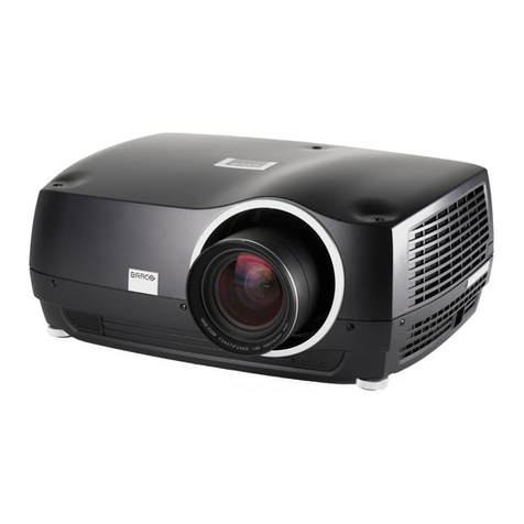
  9. Barco R1306981K(R12) User manual

Barco R1306981K(R12) User manual

BARCO PROJECTION SYSTEMS
Date:29.05.2001
INSTALLATION MANUAL
Replacement of the DLP UHB (Engine) in the
ELM series projectors
R1306981K(R12)
R1306991K(G10)
Art.No.:R5976199Rev: 00
KIT ENGINE
ELM
Due to constant research, the information in this manual is subject to change without notice.
Produced by BARCO NV, May 2001.
All rights reserved.
Trademarks are the rights of their respective owners.
BARCO n.v./Projection Systems
Noordlaan 5
B-8520 Kuurne
Belgium
Tel : +32/56/368211
Fax : +32/56/351651
E-mail : [email protected]
Visite Barco at the web : http://www.barco.com
Printed in Belgium
BARCO  3  Projection Systems
Service and Assembly Warnings
Who This installation must be performed by authorized technical personnel only, trained
concerning Ultraviolet Radiation and Electrical shock hazards and protective measures
described on this note.
General
CAUTION
Before attempting to remove any of the projectors covers, the
projector has to be turned off and disconnected from the wall
outlet to minimize the risk of electric shock.
Before starting with the Replacement of the Engine, always let
cool down the projector after operation in order to reduce the heat
on the cold mirror and to avoid burns.
WARNING
Ultraviolet Radiation (UV) Hazards
The lamp contained in this product is an intense source of light and heat. One compo-
nent of the light emitted from this lamp is ultraviolet light. Ultraviolet (UV) light or UV
radiation from this lamp can produce similar effects on the skin and eyes that sunlight
does. Prolonged exposures to low levels of ultraviolet radiation can tan the skin, but
significant exposures can cause sunburns and chronic exposures have been linked to
skin cancer. Eye exposure to significant levels of UV radiation can cause photokeratitus
or welders flash. Chronic eye exposure to significant levels of UV radiation can result
in cataracts.
Protect yourself and your employees by making them aware of the hazards and how to
protect themselves. The best method of protection is to avoid or prevent exposure to
the UV radiation from the lamp. Enclosing the UV radiation is the preferred method.
Another effective method uses distance. Increasing the distance from the lamp, de-
creases the potential hazard from the UV radiation.
Protecting the skin can accomplished by wearing tightly woven garments and gloves.
Protecting the eyes from UV can be accomplished by wearing safety glasses that are
designed to provide UV protection. In addition to the UV, the visible light from the lamp
is intense and should be considered when choosing protective eyewear.
Note: Some medications are known to make individuals extra sensitive to UV radiation.
(The American Conference of Governmental Industrial Hygienists (ACGIH) recom-
mends occupational UV exposure for an 8-hour day to be less than 0.1 microwatts per
square centimeters of effective UV radiation. An evaluation of the workplace is advised)
PRODUCT CARE
Installation Kit: - The Engine is designed for use ONLY with the BARCO ELM series
projectors.
Replacement parts - When replacement parts are required, be sure the service
technician has used original BARCO replacement parts or authorized replacement
parts which have the same characteristics as the BARCO original part.
Unauthorized substitutions may result in degraded performance and reliability, fire,
electric shock or other hazards. Unauthorized substitutions may void warranty.
Under no circumstances are BARCO parts repairable by anyone other than BARCO.
BARCO  4  Projection Systems
Contents of the Kit
Kit Contents The kit contains the following items :
Art. No Description Quantity Art. No Description Quantity
R1306981 DLP SXGA UHB (R12) 1
or
R1306991 DLP XGA UHB (G10) 1
R5976199 MAN INS G10/R12ELM ENGINE 1
Illustration
Warning
ATTENTION
OBSERVE PRECAUTIONS
FOR HANDLING
ELECTROSTATIC
DISCHARGE
SENSITIVE
DEVICES
R818727 FRM G10 ELM FIX PLT PACKAG 1
R818727
Remark In the following chapters we will (for practical reasons) refer to DLP (S)XGA UHB as
Engine.
BARCO  5  Projection Systems
Removing the top and side projector covers
What has to be
done
To access the Engine the top and the side projector covers have to be removed.
Necessary Tools Screwdriver 5 mm - Allen Key 5mm
Warning ! Refer to Service and Assembly WARNINGS in front of document.
Removing the top
cover
To remove the top cover, follow the next procedure:
1
2
3
4
5
1
1&2
1&2
1
1
Unplug the Power cord plug from the projector power input
connector (A).
Remove the linch pin (B) from the clevis pin (C) on each
stud (D).
Slide the clevis pin out of the stud.
Remove the 4 bolts (E) holding top cover to main frame.
Remove the metal top cover.
Step Action Image
Illustrations
A
D C B
Image 1
E
Image 2
to be continued on next page
BARCO  6  Projection Systems
Removing the top and side projector covers (Continued)
Illustrations
Image 2
Removing the
side covers
To remove side covers, follow the next procedure:
1
2
3
1
1
3
On the Signal input side of the projector, turn the indicated
bolts (A) a quarter turn counter clockwise to unlock.
Flip the bottom of the side cover (B) a little towards you
and pull it downwards to remove.
Do the same for the other side cover (bolts C on image 3)
Step Action Image
A
Image 1
B
C
BARCO  7  Projection Systems
Access to the Engine module
What has to be
done
The studs and crossbar above the Formatter box and the cover of the box itself have
to be removed to access the module
Necessary Tools Small screw driver flat-blade 4.5mm
Removing the
studs
To remove the studs and crossbar, follow the next procedure:
1
2
3
2
1
Remove the 3 bolts (A) fixating each stud to main frame
Remove the bolt (B) fixating the wrist band (C) to cross
bar.
Remove both studs and crossbar.
Step Action Picture
To be continued on next page
Illustrations
A
B
Picture 1
C
Picture 2
Picture 3
BARCO  8  Projection Systems
Access to the Engine (continued)
Removing the
Formatter box
cover
To remove the Formatter box cover, follow the next procedure:
1
2
3
4
1&2
2
1
Loosen the 6 spring screws (A) fastening the box cover to
frame.
Remove the bolt (B) fixating the wrist band (C) to frame.
Disconnect the connectors (D) of the 2 FANS assuring top
cooling for the engine.
Remove the box cover now.
Step Action Picture
Illustrations
AB
C
D
A
Image 1
Image 2
To be continued on next page
BARCO  9  Projection Systems
Access to the Engine (continued)
Illustration
Location of the
Engine (Right
view of the
Projector)
Image 3
Remark Depending on the projector the picture may not always coincide with the reality (metallic
frame slightly different etc,...). However, the procedure for removing the Engine re-
mains the same for every G10 or R12 ELM projector.
BARCO  10  Projection Systems
Formatter module Disconnection
What has to be
done
The 3 flex foil connectors have to be removed from the module.
WARNING Take all necessary precautions while handling the Static-Sensitive Formatter
module.
Removing the
connectors
To remove the connectors, follow the next procedure:
1
2
3
1
1
2
Push for each flexfoil connector the lock clips (A) outside
to unlock.
Carefully unplug the 3 flexfoil connectors (B) from module
Unlock the module by pulling upwards both module locks
(C)
Step Action Picture
Illustrations
Picture 1
A
B
BARCO  11  Projection Systems
Removing the Cables
What has to be
done
The remaining cables connected to the engine have to be removed.
Necessary Tools none
To be continued on next page
Removing the
studs
To remove those cables, follow the next procedure:
1
2
3
1
2&3
4(next
page)
Remove the bleu cable connector (A) coming from the
Temp & Motor Control module.
Untie the cables from the frame by unlocking the clips (B).
Depending on the projector, these cables can be fixed
under or above the metallic frame ( see 2&3)
Remove the 8 connectors (C) on the module
Step Action Picture
Illustrations
A
Image 1
Picture 3
B
Picture 2
BARCO  12  Projection Systems
Removing the Cables (Continued)
Illustrations
Picture 4
C
BARCO  13  Projection Systems
Removing the Engine
What has to be
done
The Engine has to be removed.
To be continued on next page
Necessary Tools Hexagon ball driver 2.5 or L-shaped driver (2.5) + pliers
Removing the
Engine
To remove the Engine, follow the next procedure:
1
2
3
4
5
1
2&3(next
page)
4(next
page)
4&5(next
Loosen the 2 screws (A).
For the third screw (B) located on the backside use a long
hexagon ball driver or the L-shaped dirver (a) in combina-
tion with the pliers (b) to unlock the screw.
Lift gently the engine from its place.
Place the engine on the support plate, by aligning it with
the guiding holes (C) and fix it with the 3 screws.
Insert the 3 flexfoil connectors in the slots (D) of the
support plate and tie each of them with the cable ties (F).
Step Action Picture
Illustrations
Image 1
Image 2
B
A
BARCO  14  Projection Systems
Removing the Engine (Continued)
Illustrations
CD
Image 5
Image 3
D
Image 4
F
a
b
BARCO  15  Projection Systems
Mounting the Engine
To be continued on next page
Removing the
Engine
To remove the Engine, follow the next procedure:
1
2
3
4
1
1
2&3(next
page)
4(next
page)
Unpack gently the engine and put it on a table
Loosen the 3 screws and remove the flexfoil plugs from
their place.
Put the engine on the lightpipe (A) and aligne it with the
guiding pins (inclined arrows on image 2).
Tighten the 3 screws (B).
For the third screw located on the backside handle as
explained in chapter Removing the Engine.
Step Action Picture
Illustrations
Image 1
D
F
What has to be
done The new Engine has to be Mounted.
Necessary Tools Hexagon ball driver (2.5mm) or L-shaped driver
pliers
BARCO  16  Projection Systems
Mounting the Engine (Continued)
Illustrations
Image 3
Image 2
A
B
Image 4
BARCO  17  Projection Systems
Formatter Module Connection
What has to be
done
The Formatter module has to be connected to the engine.
WARNING Take all necessary precautions while handling the Static-Sensitive Formatter
module.
to be continued on next page
Connection of
the module
To reconnect the Formatter module, follow the next procedure:
1
2
3
4
5
1
1&2(next
page)
2
3
3
Slide the module slightly upwards to facilitate the following
operations.
Caution: Inspect the plug for pin damage and be sure the
plug fits correctly the connector to avoid damage to the
pins.
Carefully insert the 3 flexfoil plugs (C) into their respective
connector.
Be aware that the red channel plug (connector in the
middle (!)on image 3 ) has to be plugged with the text on it
upside down.
Lock each plug by pushing the plug clips (D) to the inside.
Slide the module fully downwards until the module seats.
Lock the module in its frame by pushing the 2 module locks
(B) downwards.
Step Action Image
Illustrations
Picture 1
BARCO  18  Projection Systems
Formatter Module Connection (Continued)
D
Image 2
C
Illustrations
B
Image 3
!
BARCO  19  Projection Systems
Replacing the Cables
What has to be
done
The remaining cables have to be connected to the engine.
Necessary Tools none
To be continued on next page
Connecting the
Cables
To connect these cables, follow the next procedure:
1
2
3
1
2
3&4(next
page)
Reconnect the bleu cable connector (A) coming from the
Temp & Motor Control module.
Plug the 8 connectors on the module (B)
Tighten the cables on the frame by locking the clips (C).
Depending on the projector these cables can be fixed
under or above the metallic frame ( see Image 3&4)
Step Action Picture
Illustrations
A
Image 1
Picture 2
B
BARCO  20  Projection Systems
Replacing the Cables (Continued)
Illustrations
Picture 4
C
Picture 3

This manual suits for next models

1

Other Barco Projector manuals

Barco R9002250 User manual

Barco

Barco R9002250 User manual

Barco BarcoData 1209S User manual

Barco

Barco BarcoData 1209S User manual

Barco LX-5 SERIES User manual

Barco

Barco LX-5 SERIES User manual

Barco BARCOREALITY 6500 User manual

Barco

Barco BARCOREALITY 6500 User manual

Barco RLM G5 Performer Manual

Barco

Barco RLM G5 Performer Manual

Barco G62 User manual

Barco

Barco G62 User manual

Barco DP4K-23B User manual

Barco

Barco DP4K-23B User manual

Barco ELM G10 User manual

Barco

Barco ELM G10 User manual

Barco SIM 7Q User manual

Barco

Barco SIM 7Q User manual

Barco DICOM THEATER User guide

Barco

Barco DICOM THEATER User guide

Barco PJWU-101B User guide

Barco

Barco PJWU-101B User guide

Barco OV-513 User manual

Barco

Barco OV-513 User manual

Barco ClickShare CS-100 User manual

Barco

Barco ClickShare CS-100 User manual

Barco Cine 8 User manual

Barco

Barco Cine 8 User manual

Barco OVF-708 User manual

Barco

Barco OVF-708 User manual

Barco F90-W13 User manual

Barco

Barco F90-W13 User manual

Barco Thor User manual

Barco

Barco Thor User manual

Barco FL40 series User manual

Barco

Barco FL40 series User manual

Barco Cineo22 User manual

Barco

Barco Cineo22 User manual

Barco R9001070 User manual

Barco

Barco R9001070 User manual

Barco R92112011 User manual

Barco

Barco R92112011 User manual

Barco CINEVERSUM 60 User manual

Barco

Barco CINEVERSUM 60 User manual

Barco iD H250 User manual

Barco

Barco iD H250 User manual

Barco BARCOVISION 8100 User manual

Barco

Barco BARCOVISION 8100 User manual

Popular Projector manuals by other brands

Digital Projection dVision Scope 1080p Specifications

Digital Projection

Digital Projection dVision Scope 1080p Specifications

motif 03976 instructions

motif

motif 03976 instructions

JVC DLA-NZ9 instructions

JVC

JVC DLA-NZ9 instructions

Philips PICOPIX PPX1020 user manual

Philips

Philips PICOPIX PPX1020 user manual

Sanyo PLC-WL2500 Command list

Sanyo

Sanyo PLC-WL2500 Command list

Sony VPL-CS1 operating instructions

Sony

Sony VPL-CS1 operating instructions

Toshiba TDP-MT700 Service manual

Toshiba

Toshiba TDP-MT700 Service manual

ADJ Ikon Profile User instructions

ADJ

ADJ Ikon Profile User instructions

3M MP 8770 Operator's guide

3M

3M MP 8770 Operator's guide

Sony VPL-ES2 Specification sheet

Sony

Sony VPL-ES2 Specification sheet

Sony VPL-CX70 Specifications

Sony

Sony VPL-CX70 Specifications

Hitachi CP-WU8460 user manual

Hitachi

Hitachi CP-WU8460 user manual

NEC NP-PH1000U specification

NEC

NEC NP-PH1000U specification

BOXLIGHT CD715x user manual

BOXLIGHT

BOXLIGHT CD715x user manual

BOXLIGHT FP-97t user guide

BOXLIGHT

BOXLIGHT FP-97t user guide

Sanyo PLC-SP10N owner's manual

Sanyo

Sanyo PLC-SP10N owner's manual

Acer H6510BD quick guide

Acer

Acer H6510BD quick guide

Mitsubishi Electric XD250U Brochure & specs

Mitsubishi Electric

Mitsubishi Electric XD250U Brochure & specs

manuals.online logo
manuals.online logoBrands
  • About & Mission
  • Contact us
  • Privacy Policy
  • Terms and Conditions

Copyright 2025 Manuals.Online. All Rights Reserved.