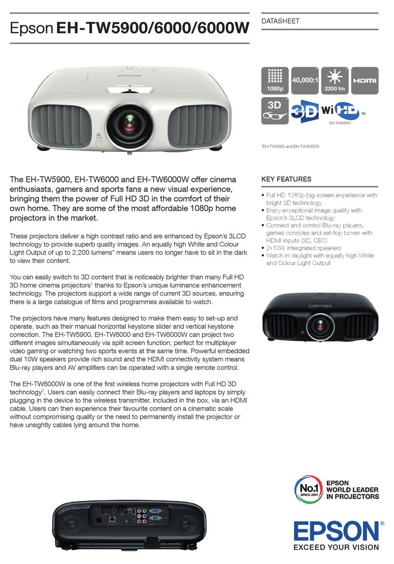
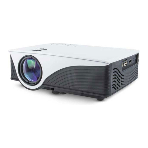
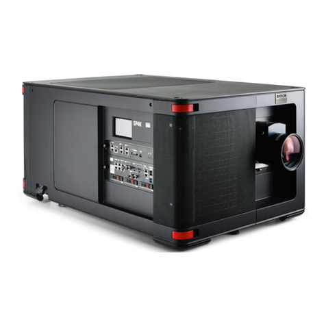
Barco SP2K-S User manual

ENABLING BRIGHT OUTCOMES
Installation manual
SP2K-S

Registered office: Barco NV
President Kennedypark 35, 8500 Kortrijk, Belgium
www.barco.com/en/support
www.barco.com
Barco NV
Beneluxpark 21, 8500 Kortrijk, Belgium
www.barco.com/en/support
www.barco.com

Changes
Barco provides this manual 'as is' without warranty of any kind, either expressed or implied, including but not
limited to the implied warranties or merchantability and fitness for a particular purpose. Barco may make
improvements and/or changes to the product(s) and/or the program(s) described in this publication at any time
without notice.
This publication could contain technical inaccuracies or typographical errors. Changes are periodically made
to the information in this publication; these changes are incorporated in new editions of this publication.
The latest edition of Barco manuals can be downloaded from the Barco web site www.barco.com or from the
secured Barco web site https://www.barco.com/en/signin.
Copyright ©
All rights reserved. No part of this document may be copied, reproduced or translated. It shall not otherwise be
recorded, transmitted or stored in a retrieval system without the prior written consent of Barco.
Trademarks
Brand and product names mentioned in this manual may be trademarks, registered trademarks or copyrights
of their respective holders. All brand and product names mentioned in this manual serve as comments or
examples and are not to be understood as advertising for the products or their manufacturers.
Product Security Incident Response
As a global technology leader, Barco is committed to deliver secure solutions and services to our customers,
while protecting Barco’s intellectual property. When product security concerns are received, the product
security incident response process will be triggered immediately. To address specific security concerns or to
report security issues with Barco products, please inform us via contact details mentioned on https://www.
barco. com/psirt. To protect our customers, Barco does not publically disclose or confirm security
vulnerabilities until Barco has conducted an analysis of the product and issued fixes and/or mitigations.
Federal Communications Commission (FCC Statement)
This equipment has been tested and found to comply with the limits for a class A digital device, pursuant to
Part 15 of the FCC rules. These limits are designed to provide reasonable protection against harmful
interference when the equipment is operated in a commercial environment. This equipment generates, uses,
and can radiate radio frequency energy and, if not installed and used in accordance with the instruction
manual, may cause harmful interference to radio communications. Operation of this equipment in a residential
area may cause harmful interference, in which case the user will be responsible for correcting any interference
at his own expense
Changes or modifications not expressly approved by the party responsible for compliance could void the
user's authority to operate the equipment
FCC responsible: Barco Inc.
3059 Premiere Parkway Suite 400
30097 Duluth GA, United States
Tel: +1 678 475 8000


5R5913197 /02 SP2K-S
1 Safety...................................................................................................................................................................................................................9
1.1 General considerations ...............................................................................................................................................................10
1.2 Important safety instructions.....................................................................................................................................................12
1.3 Product safety labels.....................................................................................................................................................................16
1.4 High Brightness precautions: Hazard Distance.............................................................................................................18
1.5 HD for fully enclosed projection systems...........................................................................................................................20
1.6 HD in function of modifying optics .........................................................................................................................................21
2 Getting started..........................................................................................................................................................................................23
2.1 Installation requirements ............................................................................................................................................................24
2.2 Unpacking the projector ..............................................................................................................................................................26
2.3 Initial inspection ...............................................................................................................................................................................31
2.4 Convention projector orientation............................................................................................................................................32
2.5 Air flow of the projector ................................................................................................................................................................33
2.6 Web Communicator.......................................................................................................................................................................34
2.7 Web Commander............................................................................................................................................................................35
2.8 Exhaust adapter (Optional) .......................................................................................................................................................36
3 Installation process..............................................................................................................................................................................37
3.1 Installation process overview...................................................................................................................................................38
4 Physical installation projector....................................................................................................................................................39
4.1 Positioning the SP2K-S...............................................................................................................................................................40
4.2 Accessing the power connections.........................................................................................................................................43
4.3 Connecting the projector with the power net ...................................................................................................................44
4.4 Connecting a UPS with the projector electronics..........................................................................................................46
4.5 Installing air exhaust adapter (Optional)............................................................................................................................49
5 Lenses & Lens holder........................................................................................................................................................................53
5.1 Available lenses...............................................................................................................................................................................54
5.2 Lens selection...................................................................................................................................................................................55
5.3 Installation of a lens.......................................................................................................................................................................56
5.4 Lens shift, zoom & focus.............................................................................................................................................................58
5.5 Scheimpflug introduction............................................................................................................................................................60
5.6 Scheimpflug adjustment..............................................................................................................................................................61
6 Input & communication ....................................................................................................................................................................65
Table of contents

R5913197 /02 SP2K-S6
6.1 Introduction.........................................................................................................................................................................................66
6.2 Cinema controller of the projector .........................................................................................................................................67
6.3 ICP-D (Integrated Cinema Processor – Direct) .............................................................................................................69
7 ICMP-X............................................................................................................................................................................................................71
7.1 ICMP-X introduction......................................................................................................................................................................73
7.2 ICMP-X HDD .....................................................................................................................................................................................75
7.3 What are the possible HDD swaps ......................................................................................................................................77
7.4 ICMP-X communication and input ports ............................................................................................................................79
7.5 ICMP-X status LEDs .....................................................................................................................................................................81
7.6 ICMP-X HDD status LEDs .........................................................................................................................................................82
7.7 ICMP-X device certificate...........................................................................................................................................................84
7.8 ICMP-X configuration via Web Communicator...............................................................................................................86
7.9 ICMP-X reset.....................................................................................................................................................................................87
7.10 Obtaining the ICMP-X certificate............................................................................................................................................88
7.11 Removing a HDD from the ICMP-X......................................................................................................................................89
7.12 Installing a HDD into the ICMP-X...........................................................................................................................................90
8 Projector Power Cycle......................................................................................................................................................................93
8.1 Explaining the power states......................................................................................................................................................94
8.2 Switching the projector ON........................................................................................................................................................96
8.3 Switching the projector OFF ....................................................................................................................................................98
9 Connectivity ............................................................................................................................................................................................ 101
9.1 Connecting to the projector for the first time................................................................................................................. 102
9.2 Software update............................................................................................................................................................................ 103
10 Convergence ......................................................................................................................................................................................... 107
10.1 Opening the sealed compartment ......................................................................................................................................108
10.2 Closing the sealed compartment .........................................................................................................................................110
10.3 Convergence controls ................................................................................................................................................................113
10.4 Converging the blue pattern onto the red pattern.......................................................................................................115
10.5 Converging the green pattern onto the red pattern....................................................................................................117
10.6 Extenders for control knobs ....................................................................................................................................................119
11 Color calibration.................................................................................................................................................................................. 121
11.1 Calibration process..................................................................................................................................................................... 122
11.2 White point calibration............................................................................................................................................................... 123
11.3 Color gamut calibration............................................................................................................................................................. 125
12 Projector covers.................................................................................................................................................................................. 127
12.1 Removal of the left side cover ............................................................................................................................................. 128
12.2 Removal of the front cover......................................................................................................................................................129
12.3 Removal of the rear filter cover............................................................................................................................................ 131
12.4 Removal of the entire rear cover ........................................................................................................................................ 132
12.5 Removal of the right side cover .......................................................................................................................................... 133
12.6 Removal of the operator side cover ................................................................................................................................. 134
12.7 Removal of the top cover ........................................................................................................................................................135
12.8 Mounting the top cover ............................................................................................................................................................ 136
12.9 Mounting the operator side cover ......................................................................................................................................137
12.10 Mounting the right side cover ...............................................................................................................................................139
12.11 Mounting the rear cover .......................................................................................................................................................... 140
12.12 Mounting the rear filter cover.................................................................................................................................................141
12.13 Mounting the front cover .......................................................................................................................................................... 142
7R5913197 /02 SP2K-S
12.14 Mounting the left side cover ................................................................................................................................................... 143
A Dimensions.............................................................................................................................................................................................. 145
A.1 Dimensions of the projector ...................................................................................................................................................146
A.2 Dimensions of the universal pedestal............................................................................................................................... 147
A.3 Dimensions of the flat-packed pedestal ..........................................................................................................................148
Glossary ..................................................................................................................................................................................................... 149
List of tools............................................................................................................................................................................................... 151
Index .............................................................................................................................................................................................................. 153

R5913197 /02 SP2K-S8

9R5913197 /02 SP2K-S
1.1 General considerations .................................................................................................................10
1.2 Important safety instructions..........................................................................................................12
1.3 Product safety labels.....................................................................................................................16
1.4 High Brightness precautions: Hazard Distance................................................................................18
1.5 HD for fully enclosed projection systems.........................................................................................20
1.6 HD in function of modifying optics ..................................................................................................21
About this chapter
Read this chapter attentively. It contains important information to prevent personal injury while installing and
using your SP2K-S projector. Furthermore, it includes several cautions to prevent damage to your SP2K-S
projector. Ensure that you understand and follow all safety guidelines, safety instructions and warnings
mentioned in this chapter before installing and using the SP2K-S projector. After this chapter, additional
“warnings” and “cautions” are given depending on the procedure. Read and follow these “warnings” and
“cautions” as well.
Clarification of the term “SP2K-S” used in this document
When referring in this document to the term “SP2K-S” means that the content is applicable for following Barco
products:
• SP2K-15S, SP2K-11S, SP2K-9S, SP2K-7S
Barco provides a guarantee relating to perfect manufacturing as part of the legally stipulated terms
of guarantee. Observing the specification mentioned in this chapter is critical for projector
performance. Neglecting this can result in loss of warranty.
Safety 1

R5913197 /02 SP2K-S10
1.1 General considerations
General safety instructions
• Before operating this equipment please read this manual thoroughly and retain it for future reference.
• Installation and preliminary adjustments should be performed by qualified Barco personnel or by
authorized Barco service dealers.
• All warnings on the projector and in the documentation manuals should be adhered to.
• All instructions for operating and use of this equipment must be followed precisely.
• All local installation codes should be adhered to.
Notice on safety
This equipment is built in accordance with the requirements of the applicable international safety standards.
These safety standards impose important requirements on the use of safety critical components, materials
and insulation, in order to protect the user or operator against risk of electric shock and energy hazard and
having access to live parts. Safety standards also impose limits to the internal and external temperature rises,
radiation levels, mechanical stability and strength, enclosure construction and protection against the risk of
fire. Simulated single fault condition testing ensures the safety of the equipment to the user even when the
equipment's normal operation fails.
Notice on optical radiation
This projector embeds extremely high brightness (radiance) lasers; this laser light is processed through the
projector's optical path. Native laser light is not accessible by the end user in any use case. The light exiting
the projection lens has been diffused within the optical path, representing a larger source and lower radiance
value than native laser light. Nevertheless the projected light represents a significant risk for the human eye
and skin when exposed directly within the beam. This risk is not specifically related to the characteristics of
laser light but solely to the high thermal induced energy of the light source; which is equivalent with lamp
based systems.
Thermal retinal eye injury is possible when exposed within the Hazard Distance (HD). The HD is defined from
the projection lens surface towards the position of the projected beam where the irradiance equals the
maximum permissible exposure as described in the chapter “Hazard Distance”.
WARNING: No direct exposure to the beam within the hazard distance shall be permitted, RG3
(Risk Group 3) IEC EN 62471-5:2015
CAUTION: Use of controls or adjustments or performance of procedures other than those specified
herein may result in hazardous radiation exposure.
Restricted access location
This product may only be installed in a restricted access location. The definition of a “restricted access
location" is a location for equipment where both of following applies:
• Access can only be gained by SERVICE PERSONNEL or by OPERATORS who have been instructed
about the reasons for the restriction applied to the location and about the precautions that shall be taken.
• Access is through the use of the tool or lock and key, or other means of security, and is controlled by the
authority responsible for the location.
Why a restricted access location: This is a RG3 product. Based on international requirements, no person is
allowed to enter the projected beam within the zone between the projection lens and the related Hazard
Distance (HD). This shall be physically impossible by creating sufficient separation height or by placing
optional barriers. Within the restricted area operator training is considered sufficient. The applicable
separation heights are discussed in “High Brightness precautions: Hazard Distance”, page 18.
Users definition
Throughout this manual, the terms SERVICE PERSONNEL and TRAINED PROJECTIONIST refers to
persons having appropriate technical training and experience necessary to be knowledgeable of potential
hazards to which they are exposed (including, but not limited to HIGH VOLTAGE ELECTRIC and
ELECTRONIC CIRCUITRY and HIGH BRIGHTNESS PROJECTORS) in performing a task, and of measures
Safety

11R5913197 /02 SP2K-S
to minimize the potential risk to themselves or other persons. The term USER and OPERATOR refers to any
person other than SERVICE PERSONNEL or TRAINED PROJECTIONISTS, AUTHORIZED to operate
professional projection systems.
The TRAINED PROJECTIONISTS may only perform the maintenance task described in the User &
Installation manual. All other maintenance tasks and service tasks must be performed by qualified SERVICE
PERSONNEL.
The DLP Cinema Systems are intended "FOR PROFESSIONAL USE ONLY" by AUTHORIZED PERSONNEL
familiar with potential hazards associated with high voltage, high intensity light beams generated by lasers.
Only qualified SERVICE PERSONNEL and TRAINED PROJECTIONISTS, knowledgeable of such risks, are
allowed to perform service functions inside the product enclosure.
Safety

R5913197 /02 SP2K-S12
1.2 Important safety instructions
To prevent the risk of electrical shock
• This projector should be operated from an AC power source. Ensure that the mains voltage and capacity
matches the projector electrical ratings. If you are unable to install the AC power requirements, contact
your electrician. Do not defeat the purpose of the grounding.
• Installation should be done according to the local electrical code and regulations by qualified technical
personnel only.
• This product is equipped with a three-terminal barrier strip for the connection of a mono phase power line
with a separate earth ground
PE. If you are unable to install the AC Requirements, contact your electrician. Do not defeat the purpose of
the grounding.
• This product is equipped with a 3-terminal barrier strip for the connection of a UPS power cord (2-pole, 3-
wire grounding).
• The electronics of the projector (UPS INLET) must be powered from a suitable UPS unit. The building has
to be provided with a circuit breaker of max 6A to protect the UPS.
• The building installation has to be provided with a circuit breaker of max 32A to protect the complete unit.
• The circuit breakers are considered as readily accessible disconnect devices that must be incorporated
externally to the equipment for removal of the power to the projector mains terminals and UPS inlet
terminals.
• The cross-sectional area of the conductors in the power supply cord should be not less than 2.5 mm² (12
AWG) while using a circuit breaker of 32A max. The power cord should have a rating depending on what
power system is available:
- Mono phase configuration: min 300V.
• The cross-sectional area of the UPS inlet cord shall be not less than 0.75 mm² (18 AWG) and has a rating
of minimum 300V.
• In case of using a circuit breaker of a current rating less than 32A, the cross-sectional area of the
conductors in the power supply cord must comply with the local electrical code regulations where the
projector is installed.
• The cable gland of the power supply cord has a clamping range between 8mm and 13 mm ( cable
diameter of the power supply cord must be in this range :8-13 mm)
• Disconnect the power to the projector mains terminals for removal of all power from the projector.
• Do not allow anything to rest on the power cord. Do not locate this projector where persons will walk on the
cord.
• Do not operate the projector with a damaged cord or if the projector has been dropped or damaged - until it
has been examined and approved for operation by a qualified service technician.
• Position the cord so that it will not be tripped over, pulled, or contact hot surfaces.
• If an extension cord is necessary, a cord with a current rating at least equal to that of the projector should
be used. A cord rated for less amperage than the projector may overheat.
• Never push objects of any kind into this projector through cabinet slots as they may touch dangerous
voltage points or short circuit parts that could result in a risk of fire or electrical shock.
• Do not expose this projector to rain or moisture.
• Do not immerse or expose this projector in water or other liquids.
• Do not spill liquid of any kind on this projector.
• Should any liquid or solid object fall into the cabinet, unplug the set and have it checked by qualified
service personnel before resuming operations.
• Do not disassemble this projector, always take it to an trained service person when service or repair work
is required.
• Do not use an accessory attachment which is not recommended by the manufacturer.
• Lightning - For added protection for this video product during a lightning storm, or when it is left unattended
and unused for long periods of time, remove all power from the projector. This will prevent damage to the
projector due to lightning and AC power-line surges.
To prevent personal injury
• To prevent injury and physical damage, always read this manual and all labels on the system before
powering the projector or adjusting the projector.
• Do not underestimate the weight of the projector. The projector weighs ±69.5 kg ( ±152.119 lbs). To prevent
personal injury a hoisting tool should be used to lift the projector.
Safety

13R5913197 /02 SP2K-S
• To prevent injury, ensure that the lens, cooling system and all cover plates are correctly installed. See
installation procedures.
• Warning: high intensity light beam. NEVER look into the lens ! High luminance could result in damage to
the eye.
•Warning: extremely high brightness projector: This projector embeds extremely high brightness
(radiance) lasers; this laser light is processed through the projectors optical path. Native laser light is not
accessible by the end user in any use case. The light exiting the projection lens has been defused within
the optical path, representing a larger source and lower radiance value than native laser light.
Nevertheless the projected light represents a significant risk for the human eye when exposed directly
within the beam. This risk is not specifically related to the characteristics of laser light but solely to the high
thermal induced energy of the light source; which is equivalent to lamp based systems.
Thermal retinal eye injury is possible when exposed within the Hazard Distance. The Hazard Distance
(HD) is defined from the projection lens surface towards the position of the projected beam where the
irradiance equals the maximum permissible exposure as described in the chapter “High Brightness
precautions: Hazard Distance”, page 18.
• Based on international requirements, no person in allowed to enter the projected beam within the zone
between the projection lens and the related Hazard Distance (HD). This shall be made physically
impossible by creating sufficient separation height or by placing optional barriers. Within the restricted area
operator training is considered sufficient. The applicable separation heights are discussed in “High
Brightness precautions: Hazard Distance”, page 18.
• The projector shall be installed in a restricted access room equipped with a key or security lock preventing
untrained persons entering the Risk Group 3 use zone.
• Switch off the projector before attempting to remove any of the projector’s covers.
• Do not place this equipment on an unstable cart, stand, or table. The product may fall, causing serious
damage to it and possible injury to the user.
• Lenses, shields or screens shall be changed if they have become visibly damaged to such an extent that
their effectiveness is impaired. For example by cracks or deep scratches.
• The associated Safety responsible of the unit must evaluate the setup before the unit may be started.
• Never point or allow light to be directed on people or reflective objects within the HD zone.
• All operators shall have received adequate training and be aware of the potential hazards.
• Strictly minimize the number of people who have access to the unit. The unit may never be operated
without permission of the responsible for safety.
• Do not put your hand or any body part in front of the beam.
Do not clean the port window when the projector is switched on.
To prevent fire hazard
• Do not place flammable or combustible materials near the projector!
• Barco large screen projection products are designed and manufactured to meet the most stringent safety
regulations. This projector radiates heat on its external surfaces and from ventilation ducts during normal
operation, which is both normal and safe. Exposing flammable or combustible materials into close
proximity of this projector could result in the spontaneous ignition of that material, resulting in a fire. For this
reason, it is absolutely necessary to leave an “exclusion zone” around all external surfaces of the projector
whereby no flammable or combustible materials are present. The exclusion zone must be not less than 40
cm (16”) for this projector.
• Do not place any object in the projection light path at close distance to the projection lens output. The
concentrated light at the projection lens output may result in damage, fire or burn injuries.
• Ensure that the projector is solidly mounted so that the projection light path cannot be changed by
accident.
• Do not cover the projector or the lens with any material while the projector is in operation. . Mount the
projector in a well ventilated area away from sources of ignition and out of direct sun light. Never expose
the projector to rain or moisture. In the event of fire, use sand, CO2or dry powder fire extinguishers. Never
use water on an electrical fire. Always have service performed on this projector by authorized Barco
service personnel. Always insist on genuine Barco replacement parts. Never use non-Barco replacement
parts as they may degrade the safety of this projector.
• Slots and openings in this equipment are provided for ventilation. To ensure reliable operation of the
projector and to protect it from overheating, these openings must not be blocked or covered. The openings
should never be blocked by placing the projector too close to walls, or other similar surface. This projector
should never be placed near or over a radiator or heat register. This projector should not be placed in a
built-in installation or enclosure unless proper ventilation is provided.
Safety

R5913197 /02 SP2K-S14
• Projection rooms must be well ventilated or cooled in order to avoid build up of heat. It is necessary to vent
hot exhaust air from projector and cooling system to the outside of the building.
• Let the projector cool completely before storing. Remove cord from the projector when storing.
To prevent battery explosion
• Danger of explosion if battery is incorrectly installed.
• Replace only with the same or equivalent type recommended by the manufacturer.
• For disposal of used batteries, always consult federal, state, local and provincial hazardous waste disposal
rules and regulations to ensure proper disposal.
To prevent projector damage
• The air filters of the projector must be cleaned or replaced on a regular basis. Cleaning the booth area
would be monthly-minimum. Neglecting this could result in disrupting the air flow inside the projector,
causing overheating. Overheating may lead to the projector shutting down during operation.
• The projector must always be installed in a manner which ensures free flow of air into its air inlets.
• In order to ensure that correct airflow is maintained, and that the projector complies with Electromagnetic
Compatibility (EMC) and safety requirements, it should always be operated with all of it's covers in place.
• Slots and openings in the cabinet are provided for ventilation. To ensure reliable operation of the product
and to protect it from overheating, these openings must not be blocked or covered. The openings should
never be blocked by placing the product on a bed, sofa, rug, or other similar surface. This product should
never be placed near or over a radiator or heat register. The device should not be placed in a built-in
installation or enclosure unless proper ventilation is provided.
• Ensure that nothing can be spilled on, or dropped inside the projector. If this does happen, switch off and
remove all power from the projector. Do not operate the projector again until it has been checked by
qualified service personnel.
• Do not block the projector cooling fans or free air movement around the projector.
• Proper operation of the projector can only be guaranteed in table mounting. It is not permitted to use the
projector in another position. See installation procedure for correct installation.
•Special care for Laser Beams: Special care should be used when DLP projectors are used in the same
room as high power laser equipment. Direct or indirect hitting of collimated laser beams on to the lens from
outside the projector body can severely damage the Digital Mirror DevicesTM in which case there is a loss
of warranty.
• Never place the projector in direct sunlight. Sunlight on the lens can severely damage the Digital Mirror
DevicesTM in which case there is a loss of warranty.
• Save the original shipping carton and packing material. They will come in handy if you ever have to ship
your equipment. For maximum protection, repack your set as it was originally packed at the factory.
• Remove all power from the projectors mains terminals before cleaning. Do not use liquid cleaners or
aerosol cleaners. Use a damp cloth for cleaning. Never use strong solvents, such as thinner or benzine or
abrasive cleaners, since these will damage the cabinet. Persistent stains may be removed with a cloth
lightly dampened with mild detergent solution.
• To ensure the highest optical performance and resolution, the projection lenses are specially treated with
an anti-reflective coating, therefore, avoid touching the lens. To remove dust on the lens, use a soft dry
cloth. For lens cleaning follow the instructions precisely as stipulated in the projector manual.
• Rated maximum ambient temperature, ta= 40°C (104°F).
• Rated humidity = 5% RH to 85% RH non-condensed.
• An external frame must be used to stack projectors.
On servicing
• Do not attempt to service this product yourself, as opening or removing covers may expose you to
dangerous voltage potentials and risk of electric shock.
• Refer all servicing to qualified service personnel.
• Attempts to alter the factory-set internal controls or to change other control settings not specially discussed
in this manual can lead to permanent damage to the projector and cancellation of the warranty.
• Remove all power from the projector and refer servicing to qualified service technicians under the following
conditions:
- When the power cord or plug is damaged or frayed.
- If liquid has been spilled into the equipment.
- If the product has been exposed to rain or water.
Safety

15R5913197 /02 SP2K-S
- If the product does not operate normally when the operating instructions are followed. Adjust only those
controls that are covered by the operating instructions since improper adjustment of the other controls
may result in damage and will often require extensive work by a qualified technician to restore the
product to normal operation.
- If the product has been dropped or the cabinet has been damaged.
- If the product exhibits a distinct change in performance, indicating a need for service.
• Replacement parts: When replacement parts are required, be sure the service technician has used original
Barco replacement parts or authorized replacement parts which have the same characteristics as the
Barco original part. Unauthorized substitutions may result in degraded performance and reliability, fire,
electric shock or other hazards. Unauthorized substitutions may void warranty.
• Safety check: Upon completion of any service or repairs to this projector, ask the service technician to
perform safety checks to determine that the product is in proper operating condition.
Safety Data Sheets for Hazardous Chemicals
For safe handling information on chemical products, consult the Safety Data Sheet (SDS). SDSs are available
Safety

R5913197 /02 SP2K-S16
1.3 Product safety labels
Light beam related safety labels
Label image Label description Label location
DANGER! CLASS 4 LASER RADIATION WHEN OPEN. AVOID EYE OR
SKIN EXPOSURE TO DIRECT OR SCATTERED RADIATION.
DANGER! RAYONNEMENT LASER DE CLASSE 4 EN CAS D’OUVERTURE.
EXPOSITION DANGEREUSE AU RAYONNEMENT DIRECT OU DIFFUS
DES YEUX OU DE LA PEAU.
危险!打开时有4类激光辐射。 避免眼或皮肤受到直射或散射辐射的照射。
Located on the light pipe
THIS PRODUCT IS IN CONFORMITY WITH PERFORMANCE STANDARDS FOR LASER PRODUCTS UNDER 21 CFR 1040, EXCEPT WITH RESPECT TO THOSE CHARACTERISTICS AUTHORIZED BY VARIANCE NUMBER 2018-V-2875 EFFECTIVE ON OCTOBER 2, 2018
ATTENTION! NE PAS REGARDER LE FAISCEAU
EVITER TOUTE EXPOSITION DIRECTE DES YEUX AU FAISCEAU
RG3 IEC EN 62471-5:2015 CLASS 1 IEC EN 60825-1:2014
DISTANCE DE SECURITE: CONSULTER LE MANUEL DE SECURITE
WARNING! DO NOT LOOK INTO THE BEAM
NO DIRECT EYE EXPOSURE TO THE BEAM IS PERMITTED
RG3 IEC EN 62471-5:2015 CLASS 1 IEC EN 60825-1:2014
HAZARD DISTANCE: CONSULT SAFETY MANUAL
RG3 IEC EN 62471-5:2015 CLASS 1 IEC EN 60825-1:2014RG3 IEC EN 62471-5:2015 CLASS 1 IEC EN 60825-1:2014
WARNING! DO NOT LOOK INTO THE BEAM; NO DIRECT EYE EXPOSURE
TO THE BEAM IS PERMITTED. RG3 IEC EN 62471–5:2015. CLASS 1 IEC
EN 60825–1:2014. HAZARD DISTANCE: CONSULT SAFETY MANUAL.
“Important safety instructions”, page 12
THIS PRODUCT IS IN CONFORMITY WITH PERFORMANCE STANDARDS
FOR LASER PRODUCTS UNDER 21 CFR 1040 EXCEPT WITH RESPECT
TO THOSE CHARACTERISTICS AUTHORIZED BY VARIANCE NUMBER
2018-V-2875 EFFECTIVE ON JANUARY 24, 2020.
ATTENTION! NE PAS REGARDER LE FAISCEAU EVITER TOUTE
EXPOSITION DIRECTE DES YEUX AU FAISCEAU. RG3 IEC EN 62471-
5:2015. CLASS 1 IEC EN 60825-1:2014. DISTANCE DE SECURITE :
CONSULTER LE MANUEL DE SECURITE
警告!勿观看光束 眼睛勿直接接触可允许暴露的光束 RG3 IEC EN 62471-
5:2015 CLASS 1 IEC EN 60825-1:2014 危害距离:请参考安全手册
警告!請勿注視光源。禁止眼睛曝露在光源照射範圍。雷射危險等級 RG3 IEC
EN 62471-5:2015 CLASS 1 IEC EN 60825-1:2014 安全危害距離:請參考安全
手冊。
Located on the projector
frame
Hazard RG3: optical radiation warning symbol
Printed on the security
label (see security label
above, located on the
projector frame)
Hazard RG3: not for household use symbol
Printed on the product
label (located on the right
side cover)
Safety

17R5913197 /02 SP2K-S
Electric related safety labels
Label image and
description Label location
Disconnect the power to the unit mains terminals and unplug power cord at
UPS inlet before removing this cover. See ID-label for ratings. WARNING :
HIGH LEAKAGE CURRENT EARTH CONNECTION ESSENTIAL BEFORE
CONNECTING SUPPLY. SEE INSTALLATION INSTRUCTIONS BEFORE
CONNECTING TO THE SUPPLY.
Déconnecter l’alimentation des bornes du réseau et déconnecter le câble de
la prise UPS avant de retirer ce couvercle. Voir l’étiquette d’identification pour
les paramètres. ATTENTION : COURANT DE FUITE ÉLEVÉ
RACCORDEMENT À LA TERRE INDISPENSABLE AVANT LE
RACCORDEMENT AU RÉSEAU VOIR LA NOTICE D’INSTALLATION
AVANT DE RACCORDER AU RÉSEAU
在取下此外殼前,斷開投影機主電源端的電源並從UPS電源插座上拔下電源
線。 額定功率參閱產品標籤。 警告:大漏電流,在接通電源之前必須先接
地。 在連接電源前請查看安裝說明書
在取下此外壳前,断开投影机主电源端的电源并从UPS电源插座上拔下电源
线。 额定功率参阅产品标签。 警告:大漏电流,在接通电源之前必须先接
地。 在连接电源前请查看安装说明书。
Printed on Mains input
cover
CAUTION! DOUBLE POLE / NEUTRAL FUSING HIGH RESIDUAL
VOLTAGE - WARNING : RISK OF ELECTRIC SHOCK SWITCH OFF AND
UNPLUG BEFORE REMOVING THIS COVER. SEE INSTRUCTIONS
BEFORE REMOVING SMPS.
注意 兩極/中性熔斷 高殘餘電壓.警告:存在觸電風險 移除此蓋板之前, 請先
關機並拔掉電源插頭 移除SMPS之前,請先閱讀說明.
ATTENTION DOUBLE PÔLE / FUSIBLE SUR LE NEUTRE HAUTE
TENSION RÉSIDUELLE - ATTENTION : RISQUE DE CHOCS
ÉLECTRIQUES. ÉTEINDRE ET DÉCONNECTER AVANT OUVERTURE DU
COUVERCLE. LIRE LES INSTRUCTIONS AVANT DE RETIRER LE SMPS.
Printed on SMPS cover
Safety

R5913197 /02 SP2K-S18
1.4 High Brightness precautions: Hazard Distance
HD
Hazard Distance (HD) is the distance measured from the projection lens at which the intensity or the
energy per surface unit becomes lower than the applicable exposure limit on the cornea or on the
skin. The light beam is considered (to be) unsafe for exposure if the distance from a person to the
light source is less than the HD.
Restriction Zone (RZ) based on the HD
The HD depends on the amount of lumens produced by the projector and the type of lens installed. See
chapter “HD in function of modifying optics”, page 21.
To protect untrained end users (as cinema visitors, spectators) the installation shall comply with the following
installation requirements: Operators shall control access to the beam within the hazard distance or install the
product at a height that will prevent spectators' eyes from being in the hazard distance. Radiation levels in
excess of the limits will not be permitted at any point less than 2.0 meter (SH) above any surface upon which
persons other than operators, performers, or employees are permitted to stand or less than 1.0 meter (SW)
lateral separation from any place where such persons are permitted to be. In environments where
unrestrained behavior is reasonably foreseeable, the minimum separation height should be greater than or
equal to 3.0 meter to prevent potential exposure, for example by an individual sitting on another individual's
shoulders, within the HD.
These values are minimum values and are based on the guidance provided in IEC 62471-5:2015 section
6.6.3.5.
The installer and user must understand the risk and apply protective measures based upon the hazard
distance as indicated on the label and in the user information. Installation method, separation height, barriers,
detection system or other applicable control measure shall prevent hazardous eye access to the radiation
within the hazard distance.
For example, projectors that have a HD greater than 1 m and emit light into an uncontrolled area where
persons may be present should be positioned in accordance with “the fixed projector installation” parameters,
resulting in a HD that does not extend into the audience area unless the beam is at least 2.0 meter above the
floor level. In environments where unrestrained behavior is reasonably foreseeable, the minimum separation
height should be greater than or equal to 3.0 meter to prevent potential exposure, for example by an individual
sitting on another individual's shoulders, within the HD. Sufficiently large separation height may be achieved
by mounting the image projector on the ceiling or through the use of physical barriers.
RA
TH
HD
SW
SW
TOP VIEW (B)
EXIT
SH
RA
PR
TH
HD
SIDE VIEW (A)
RZ
H<SH
H>SH
LRZ
LRZ
RZ
Image 1–1
ASide view
BTop view
RA Restricted Access location (boot area of projector).
TH Theater
RZ Restriction Zone in the theater
HD Hazard Distance
LRZ Length Restriction Zone in the theater
HHeight between surface floor and the light beam
SH Separation Height
SW Separation Width
Based on national requirements, no person is allowed to enter the projected beam within the zone between
the projection lens and the related hazard distance (HD). This shall be physically impossible by creating
Safety

19R5913197 /02 SP2K-S
sufficient separation height or by placing barriers. The minimum separation height takes into account the
surface upon which persons other than operator, performers or employees are permitted to stand.
On Image 1– 2 a typical setup is displayed. It must be verified if these minimum requirements are met. If
required a restricted zone (RZ) in the theater must be established. This can be done by using physical barrier,
like a red rope as illustrated in Image 1–2.
The restricted area sticker can be replaced by a sticker with only the symbol.
PR
RZ
RESTRICTED
AREA
RESTRICTED
AREA
Image 1–2
USA market
For LIPs (Laser Illuminated Projectors) installed in the USA market other restriction zone conditions apply.
LIPs for installation in restrained environment (cinema theaters, business rooms, class rooms, museums ...)
shall be installed at height vertically above the floor such that the bottom plane of the hazard distance zone
shall be no lower than 2.5 meters above the floor. Horizontal clearance to the hazard distance zone shall be
not less than 1 meter. Alternatively, in case the height of the separation barrier for the horizontal clearance is
at least 1 meter high then the horizontal clearance (SW) can be reduced to:
• 0 meter if the height of the hazard zone is minimum 2.5 meter.
• 0.1 meter if the height of the hazard zone is minimum 2.4 meter.
• 0.6 meter if the height of the hazard zone is minimum 2.2 meter.
LIPs for installations in unrestrained environment (concerts, ...) shall be installed at a height vertically above
the floor such that the bottom plane of the Hazard distance Zone shall be no lower than 3 meters above the
floor. Horizontal clearance to the hazard distance zone shall be not less than 2.5 meters. Any human access
horizontally to the Hazard Zone, if applicable, shall be restricted by barriers. If human access is possible in an
unsupervised environment, the horizontal or vertical clearances shall be increased to prevent exposure to the
hazard distance zone.
The LIP shall be installed by Barco or by a trained and Barco-authorized installer or shall only be transferred to
laser light show variance holders. This is applicable for dealers and distributors since they may need to install
the LIP (demo install) and/or they transfer (sell, rent, lease) the LIP. Dealers and distributors shall preserve
sales and installation records for a period of 5 years. Variance holders may currently hold a variance for
production of Class IIIB and IV laser light shows and/or for incorporating RG3 LIPs. Laser light show variance
The installation checklist for laser illuminated RG3 projectors must be fully completed after the installation.
The installation checklist can be downloaded from the Barco website. The installer shall preserve the checklist
for a period of 5 years.
Install one or more readily accessible controls to immediately terminate LIP projection light. The power input at
the projector side is considered as a reliable disconnect device. When required to switch off the projector,
disconnect the power cord at the projector side. In case the power input at the projector side is not accessible
(e. g. truss mount), the socket outlet supplying the projector shall be installed nearby the projector and be
easily accessible, or a readily accessible general disconnect device shall be incorporated in the fixed wiring.
Safety

R5913197 /02 SP2K-S20
1.5 HD for fully enclosed projection systems
HD
Hazard Distance (HD) is the distance measured from the projection lens at which the intensity or the
energy per surface unit becomes lower than the applicable exposure limit on the cornea or on the
skin. The light beam is considered (to be) unsafe for exposure if the distance from a person to the
light source is less than the HD.
Restriction Zone (RZ) based on the HD
The projector is also suitable for rear projection applications; projecting a beam onto a defuse coated
projection screen. As displayed in Image 1– 3 two areas should be considered: the restricted enclosed
projection area (RA) and the observation area (TH).
RA TH
sw
PD
HDDIFFUSE
sw
RZ
sw sw
PR
HD
REFLECTION
RESTRICTED
AREA
RESTRICTED
AREA
Image 1–3
RA Restricted Access location (enclosed projection area).
PR Projector.
TH Theater (observation area).
RZ Restriction Zone.
PD Projection Distance.
SW Separation Width. Must be minimum 1 meter.
For this type of setup 3 different HD shall be considered:
• HD as discussed in “High Brightness precautions: Hazard Distance”, page 18, relevant for intrabeam
exposure.
• HDreflection : the distance that has to be kept restrictive related to the reflected light from the rear projection
screen.
• HDdiffuse : the relevant distance to be considered while observing the diffuse surface of the rear projection
screen.
As described in “High Brightness precautions: Hazard Distance”, page 18, it is mandatory to create a
restricted zone within the beam areas closer than any HD. In the enclosed projection area the combination of
two restricted zones are relevant: The restricted zone of the projected beam toward the screen; taking into
account 1 meter Separation Width (SW) from the beam onward. Combined with the restricted zone related to
the rear reflection from the screen (HDreflection); also taking into account a 1 meter lateral separation.
The HDreflection distance equals 25% of the difference between the determined HD distance and the projection
distance to the rear projection screen. To determine the HD distance for the used lens and projector model see
chapter “HD in function of modifying optics”, page 21.
HDreflection = 25% (HD – PD)
The light emitted from the screen within the observation shall never exceed the RG2 exposure limit,
determined at 10 cm. The HDdiffuse can be neglected if the measured light at the screen surface is below 5000
cd/m² or 15000 LUX.
Safety
Table of contents
Other Barco Projector manuals

Barco
Barco Galaxy 9 HC+ Owner's manual

Barco
Barco Cine VERSUM 80 User manual

Barco
Barco HDQ 4K35 User manual

Barco
Barco DP2K-10Sx User manual

Barco
Barco iCon H250 User manual

Barco
Barco SLM R12+ Performer User manual

Barco
Barco UDM W22 User manual

Barco
Barco CINE 6 User manual

Barco
Barco UDX Series User manual

Barco
Barco Prometheus III User manual

Barco
Barco SIM 7QP HB User manual

Barco
Barco UDX R9008600 User manual

Barco
Barco F400 User guide

Barco
Barco GRAPHICS 1209S User manual

Barco
Barco R5976336 User manual

Barco
Barco G60 W Series User manual

Barco
Barco CineVersum 120 User manual

Barco
Barco CX-50 User manual

Barco
Barco 90 00719 User manual

Barco
Barco GRAPHICS 9300 User manual