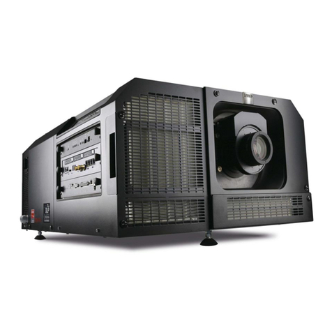
Barco R9850010 User manual

INSTALLATION MANUAL
Screen Assemby Blocks
3x3 (R9850010)
4x3 (R9850020)
4x4 (R9850030)
Day Light
Displays
DAY LIGHT DISPLAY SYSTEMS

Due to constant research, the information in this manual is subject to change without notice
Trademarks are the rights of their respective owners
All rights reserved
Produced by BARCO NV, 19/06/2001
BARCO n.v./Daylight Display Systems
Noordlaan 5
B-8520 Kuurne
Belgium
Tel : +32/56/368828
Fax : +32/56/368824
e-mail: [email protected]
Visit Barco on the web: http://www.barco.com
Printed in Belgium

Art. No: R5976076Date: 19/06/2001
INSTALLATION MANUAL
Rev: 03
Screen Assemby Blocks
3x3 (R9850010)
4x3 (R9850020)
4x4 (R9850030)
Day Light
Displays
DAY LIGHT DISPLAY SYSTEMS


Contents
Order Numbers ...................................................... 6
Ordering spare/ replacement parts ............................................................. 6
Safety Guide Lines ................................................ 7
Safety guide lines ......................................................................................... 7
Personnel .............................................................................................. 7
Caution .................................................................................................. 7
Product Care ......................................................................................... 7
Safety Notice .......................................................... 8
IMPORTANT WARNINGS .......................................................................... 8
Risk of electric shock ......................................................................... 8
Maximum ambient temperature ......................................................... 8
High leakage current ........................................................................... 8
Risk of personnel injury ..................................................................... 8
Flammable materials .......................................................................... 8
Risk of electric shock/ Risk of fire .................................................... 8
Disconnect device .............................................................................. 8
This equipment must be earthed ....................................................... 8
Power system..................................................................................... 8
Mains cords ......................................................................................... 8
Additional Safety Notice ....................................... 9
IMPORTANT WARNINGS .......................................................................... 9
System Overview ................................................. 10
Introduction .................................................................................................. 10
Support Structures ...................................................................................... 10
Overview.................................................................................................... 10
Source utilisation of system ...................................................................... 10
Image 1 System block diagram ....................................................... 11
General Notice ............................................................................................ 11
Image 2 Assembly on floor ............................................................... 11
Tile Specification ................................................ 12
Tile Specification ........................................................................................ 12
Image 1 Front Access Tools ............................................................. 12
Cabling & Caliber ................................................ 13
What has to be done .................................................................................. 13
Necessary Tools ....................................................................................... 13
Cables ......................................................................................................... 13
Image 1 Power Source cable ...........................................................13
Image 2 Power & Data linking cables .............................................. 14
Image 3 Safety Cable ........................................................................14
Image 4 Caliber tool ........................................................................... 14
Example Installation ........................................... 15
What has to be done .................................................................................. 15
Preparation .................................................................................................. 15
Image 1 Example ............................................................................... 15
Assembly Preparation ......................................... 16
What has to be done .................................................................................. 16
Necessary Tools ....................................................................................... 16
General Joint/Connections ........................................................................ 16
Image 1 Hammer Bolt joint ............................................................... 16
Image 2 gap between profiles ........................................................... 17
Image 3 sides of profiles .................................................................... 17
Image 4 angle between profiles ........................................................17
Assembly Connection .......................................... 18
What has to be done .................................................................................. 18
Necessary Tools ....................................................................................... 18
Disconnecting Left Sides ...........................................................................18
Connecting Side to Side ............................................................................ 18
Disconnecting Bottom Side ........................................................................ 19
Connecting Top to Bottom ......................................................................... 19
Connecting Left & Top................................................................................ 20
Image 1 Left side removed ...............................................................21
Exploded Image1 ............................................................................... 21
Image 2 Right side Springs ............................................................... 22
Exploded Image 2 ..............................................................................22
Image 3 Bottom side removed ..........................................................23
Exploded Image 3 ..............................................................................24
Image 4 Left & bottom side removed ...............................................25
Exploded Image 4 ..............................................................................26
Tile Mounting ....................................................... 27
What has to be done ..................................................................................27
Necessary Tools ....................................................................................... 27
Image1 Tile attachments ....................................................................27
Mounting a Tile ...........................................................................................27
Image 2 Tile Mounting ....................................................................... 28
Exploded Views 2 Tile Mounting Points ..........................................28
Image 3 Safety cable .........................................................................29
Tile Inter-Connection Cabling ............................ 30
What has to be done ..................................................................................30
Necessary Tools ....................................................................................... 30
Image 1 Tile rear ................................................................................ 30
Tile Cabling ................................................................................................. 30
Power Connections ............................................. 31
What has to be done ..................................................................................31
Necessary Tools ....................................................................................... 31
Power Connections ................................................................................... 31
Image 1 Power Box ........................................................................... 31
Image 2 Power linking ....................................................................... 32
Data Connections ................................................ 33
What has to be done ..................................................................................33
Necessary Tools ....................................................................................... 33
Data Connections ....................................................................................... 33
Image 1 Data linking ........................................................................... 34
Wall Trim .............................................................. 35
What has to be done ..................................................................................35
Necessary Tools ....................................................................................... 35
Trim ............................................................................................................. 35
Mounting ...................................................................................................... 35
Image 1 Trim around Wall ................................................................. 35
Tile Accessing ...................................................... 36
What has to be done ..................................................................................36
Necessary Tools ....................................................................................... 36
Back Access .............................................................................................. 36
Front Access .............................................................................................. 36
Hot Swap .................................................................................................... 36
Image 1 Back Access ....................................................................... 37
Image 2 Front Access ....................................................................... 37
Digitizer ................................................................ 38
What has to be done ..................................................................................38
Necessary Tools ....................................................................................... 38
Digitizer ........................................................................................................ 38
Connections ................................................................................................ 38
Image 1 Front Digitizer .......................................................................38
Image 2 Back Digitizer .......................................................................38
Complete System SetUp ..................................... 39
What has to be done ..................................................................................39
Necessary Tools ....................................................................................... 39
Connections ................................................................................................ 39
Image1 System connection. ............................................................. 39

R9828832 ....... DIGITIZER ...............................................................
R9850420 ....... DIGITIZER ......................................... MIXER+LVDS
R9850080 ....... DIGITIZER ........................................ 19"IP54 CASE
R9850361 ....... DLITER TRUSS BEAM DUAL ..................................
R9850360 ....... DLITER TRUSS BEAM SINGLE ...............................
R9850060 ....... DLITE PC DATA CARD ...........................................
R9850050 ....... DLITEPOWER/FUSE BOX ......................................
R9850350 ....... DLITERENTING SYSTEMS .....................................
R9850070 ....... DLITEROOTER BOX ..............................................
R9850210 ....... DATA CABLE ................................................. 1.5M
R9850270 ....... DUMMY DATA PLUG ......................................... X2
R9850220 ....... DATA CABLE .................................................... 5M
R9850230 ....... DATA CABLE ................................. DIGITIZER-TILE
R9850250 ....... POWERCABLE ............................................. 4.5M
R9850240 ....... POWERCABLE .............................................. 0.6M
R9850280 ....... DUMMYPOWER PLUG ...................................... X5
R9850260 ....... POWERCABLE ................................................. 9M
R9850351 ....... DIVPERIPHERALS .................................................
R9850100 ....... DLITEAEC ..............................................................
R9850040 ....... DLITE CTRL SOFT ..................................................
R9850090 ....... DLITELDL ...............................................................
R9004001 ....... DLITE L5 P14 VGN7 G1 .........................................
R9004006 ....... DLITE L5 P14 VGN7 G1M ......................................
R9004000 ....... DLITE L5 P14 VGN7 G2 .........................................
R9004005 ....... DLITE L5 P14 VGN7 G2M ......................................
R9004021 ....... DLITE L5 P19 VGN10 G1 .......................................
R9004020 ....... DLITE L5 P19 VGN10 G2 .......................................
R9004030 ....... DLITE L5 P28 ..........................................................
R9004010 ....... DLITE L5 P28 VGN14 .............................................
R9004015 ....... DLITE L5 P28 VGN14 M .........................................
Order Numbers
Ordering spare/
replacement parts
R9850290 ....... DLITEFRONT ACCESS .................................... P14
R9850300 ....... DLITEFRONT ACCESS .................................... P19
R9850310 ....... DLITEFRONT ACCESS .................................... P28
R9850110 ....... DLITEFLIGHT-CASE .............................. BTM+TOP
R9850120 ....... DLITEFLIGHT-CASE ............................... 1 LAYER
R9850130 ....... DLITEFLIGHT-CASE .................................... 1TILE
R9850180 ....... DLITEFLIGHT-CASE ............................. 2 RENTAL
R9850385 ....... DLITERTRIM ............................................ L1.344 M
R9850375 ....... DLITERTRIM ............................................. L0.896M
R9004999 ....... LEDCOMPLETE SYSTEM ......................................
R9850410 ....... SOFTOMNIPOINT CTRL .........................................
R9850200 ....... FIBERLINKMEDIUM ............................... RECEIVER
R9850190 ....... FIBERLINKMEDIUM ........................ TRANSMITTER
R9850430 ....... FIBERCABLE .................................................. 50M
R9850431 ....... FIBERCABLE ................................................ 100M
R9850432 ....... FIBERCABLE ................................................ 150M
R9850433 ....... FIBERCABLE ................................................ 200M
R9850434 ....... FIBERCABLE ................................................ 250M
R9850435 ....... FIBERCABLE ................................................ 300M

BARCO 7 Daylight Display Systems
Personnel
This installation must be performed by authorized and qualified technical personnel only.
Accredited Safety Officers must ensure the safety of the site, construction, assembly, connection, use, dismantling, transport
..etc. of such safety critical systems.
Caution
Installation should be performed only after you are thoroughly familiar with all of the proper safety checks and installation
instructions. To do otherwise increases the risk of hazards and injury to the user.
Assembly parts are designed for intended use only in conjunction with BARCO Day Light Displays.
Do not modify and/or replicate any component. BARCO uses specific materials and manufacturing processes in order to
achieve part strength. Consult BARCO for assistance with custom applications.
Always follow BARCO Installation Instructions. Contact BARCO if you should have any question regarding the safety of an
application.
The manufacturer assumes no liability for incorrect, inadequate, irresponsible or unsafe assembly of systems.
Product Care
Structural & Mounting Components should be kept dry, clean, lubricated (only if recommended), coated properly, and otherwise
maintained in a manner consistent with part design. BARCO products must be used in a manner consistent with their design
and inspected on a routine basis for security, wear, deformation, corrosion and any other circumstances that may affect the
load handling capability of the part.
BARCO recommends inspections at regular intervals for all installations and increasing in frequency for more critical
installations. If a part is found to have damage, which may cause a decrease in load capability, the part must be removed for
service or replaced immediately.
Under no circumstances are BARCO parts repairable by anyone other than BARCO.
Safety Guide Lines
Safety guide lines
LOCKING MECHANISMS
SECURELY ENGAGED
ALL JOINING EDGES
MIND YOUR
FINGERS
HEAVY LOADS
HARD HATSUSPENDED LOADS

BARCO 8 Daylight Display Systems
The exclamation point within a triangle is intended to tell the
user that important operating and/or servicing instructions are
included in the technical documentation for this equipment.
The lightning flash with an arrowhead within a triangle is
intended to tell the user that parts inside this product may
cause a risk of electrical shock to persons.
Risk of electric shock
Maximum ambient temperature
The maximum recommended ambient temperature for the LED wall is 50 ° C, the minimum temperature is -20 ° C.
High leakage current
The combination of multiple tiles in an installation results in increased levels of leakage current.
In order to avoid risk of electric shock due to high leakage current, proper grounding of the installation is required.
Risk of personnel injury
Secure all tiles in the rack. As a supplementary safeguard, and in order to protect against the risk of personnel injury,
each tile should be attached to the rack by a safety cable.
Flammable materials
Keep flammable materials away from the installation (such as curtains). A lot of energy is transferred into heat. The
installation should be such that the amount of air flow required for safe operation of the equipment is not compromised.
Proper ventilation must be provided.
Risk of electric shock/ Risk of fire
Power cables and connectors have been designed with special properties for outdoor use, and resistance against ingress of
water. Use only the factory recommended power cables and connectors.
Using other cables and connectors may result in risk of electric shock and risk of fire.
To protect against risk of fire by overloading of power cables, MAXIMUM 6 TILES in one column may be connected in
parallel. Each source cable supplying a column of MAXIMUM 6 TILES should be protected by a circuit breaker or fuses
rated 16 A / 250 V.
Disconnect device
When the appliance inlets of the individual tiles are not accessible, the socket outlets supplying the rack shall be installed
near the equipment and be easily accessible, or a readily accessible general disconnect device shall be incorporated in the
fixed wiring.
This equipment MUST be earthed
In order to protect against risk of electric shock, the installation should be properly grounded. Defeating the purpose of the
grounding type plug will expose you to the risk of electric shock.
Power system
It is recommended to use a TN-S power distribution system (a power distribution system with a separate neutral and
grounding conductor) in order to avoid large ground currents loops due to voltage differences in the neutral conductor. The
total electrical installation should be protected by an appropriate rated disconnect switch, circuit breakers and Ground Fault
Current Interrupters. The installation shall be done according to the local electrical installation codes. In Europe special
attention should be given to EN 60364, the standard for electrical installation of buildings. In Germany VDE 0100 should be
adhered to.
Mains cords
The power cords delivered with this system have special properties for safety. They are not user serviceable. If the power
cords are damaged, replace only with new ones. Never try to repair a power cord.
Safety Notice
IMPORTANT
WARNINGS

BARCO 9 Daylight Display Systems
Read these instructions.
Keep these instructions.
Heed all warnings.
Follow all instructions.
IMPORTANT, plug holder clamps must be locked firmly on all display tile units and power boxes to prevent
the possible ingress of fluids or solid particles. Replace damaged clamps or seals immediately.
Do NOT submerge fully or partly in water or other liquids.
Clean only with materials or chemicals that are inert, nonabrasive, noncorrosive and non-marking. Consult
the manufacturer for further advice should any doubts exist regarding any cleaning procedure.
Do not block ventilation openings. Install in accordance with the manufacturers instructions.
Do not install near any heat sources such as radiators, heat registers, stoves, or other apparatus (including
amplifiers) that produce heat.
Do not defeat the safety purpose of the polarized or grounding type plugs/sockets. If the provided sockets/
plugs are damaged then replacement of the defective parts must be undertaken immediately.
Protect the power/data cords from being walked on or pinched particularly at plugs, convenience receptacles,
and the point where they exit from the apparatus. Replace damaged power/data cords immediately.
Only use attachments/accessories specified by the manufacturer.
Disconnect the power to this apparatus during lightning storms or provide suitable additional lightning
protection. Unplug this apparatus when unused for long period of time.
Refer all servicing to qualified service technicians/personnel. Servicing is required when the apparatus has
been damaged in any way, such as power-supply cord or plug is damaged, the apparatus does not operate
normally, or has been dropped.
Use only with systems or peripherals specified by the manufacturer, or sold with the apparatus. Use caution
during lifting/moving or transporting to avoid damage by possible tipping.
Additional Safety Notice
IMPORTANT
WARNINGS

BARCO 10 Daylight Display Systems
System Overview
The three fundamental elements of a Day Light Display Rental System are:
•The Day Light Display building frames (consists of the different Day Light Display tiles
& assembly frames).
•Day Light Display Digitizer (for image processing, conversion and conditioning)
•DLite Display Control Software (controls the Digitizer as well as the Day Light Display
tiles via a PC).
Overview
The Day Light Display Digitizer processes all source signals for digital distribution to
every Day Light Display tile. The Digitizer may be accessed directly or via the DLite
Display Control Software. This software is designed as a user interface to be used in
conjunction with the Digitizer and Day Light Display, this can be used when connected
to the Digitizer through a serial RS232 connection.
Support
Structures
Screen supporting/securing structures are not described herein, as these will vary from
system to system, but some factors to be aware of and precisely calculated for are:
1. Weight tolerances
2. Ceiling heights (floor or suspended)
3. Ballast loads (for base stand assemblies)
4. Front or rear clearances
5. Stacking limitations
6. Environmental conditions
7. Location
8. Ground clearances
9. Ground stability
10. Local regulations regarding such installations
Support structures must be assessed on an individual basis, never construct a wall if
there is uncertainty regarding the stability of an installation or the load holding
capabilities. Consult Barco for advise on professional rigging organizations, if doubts on
a systems viability are in question.
Introduction The assembly of a system due to the multitude of possible screen sizes / configurations
is difficult to assume. Three basic building frames are available having tile
arrangements in the ratios 3x3, 4x3 & 4x4, each capable of being mounted horizontally
or vertically. This modular concept gives rise to configurations of unlimited possibility,
screen dimensions of the most desirable sizes can be rapidly constructed, with
maximum flexibility.
The built-in intelligence allows the system to configure itself regardless of the shape
and size of the screen. The mechanical flexibility enables easy installation and quick
servicing.
Assemble displays on the ground and then raise to their desired position, depending on
the circumstances and facilities available.
Assembly displays are only to be used in conjunction with BARCO DLite Modules.
Source utilisation
of system
Composite Video (2x),
S-VHS (2x),
Component Video,
RGB,
SDI and
PC Data.
continued on next page

BARCO 11 Daylight Display Systems
General Notice The assembly of a wall due to the flexibility in screen size is difficult to predict, so a
description of how to connect assembly blocks to one another will form a good propriety
step.
This manual describes a simple installation using four Assembly Blocks of size 3x4.
Wall securing or supporting structures are not included.
Always assemble a wall flat on the ground and then raise to its vertical position,
dependent on the circumstances and facilities available.
Image 1 System
block diagram
Image 2
Assembly on
floor
System Overview (Continued)

BARCO 12 Daylight Display Systems
Tile Specification
Three front access tools exist for removing tiles via the front of the Display (7mm/
10mm/28mm). 10mm not shown.
Image 1 Front
Access Tools
For safety reasons, it is not recommended to use any other parts than those specified.Tile Specification
Dlite 7HR Dlite 10 Dlite 14HR Dlite 14 Dlite 28
Article Number R763170 R763340 R763156 R763195 R763301
Visual Resolution 7 mm 9.3 mm 14 mm 14 mm 28 mm
(mm)
Physical Resolution 14 mm 18.6 mm 14 mm 28 mm 28 mm
(mm)
Viewing Angle
(minimum 50% brightness)
Horizontal 120° 120° 120° 120° 120°
Vertical 60° 60° 60° 60° 60°
Light Output
(at 6,500° K) 6,500 Nit 6,500 Nit 7,000 Nit 6,500 Nit 7,000 Nit
(Individual LED corrected, Wall calibrated) 5,000 Nit 5,000 Nit 5,500 Nit 5,000 Nit 5,500 Nit
Number of LEDs
LEDs / m² 25,600 14,350 25,600 6,400 6,400
LEDs / ft² 2,379 1,334 2,379 594 594
Power Consumption
Watts / m²
Maximum (Full white specification) 1,750 W 1,750 W 2,200 W 1,750 W 2,200 W
Average (Video content, 20% white) 350 W 350 W 450 W 350 W 450 W
Watts / ft²
Maximum (Full white specification) 163 W 163 W 204 W 163 W 204 W
Average (Video content, 20% white) 32 W 32 W 42 W 32 W 42 W
Weight
Weight / m² 71.5 kg 71.5 kg 71.5 kg 71.5 kg 71.5 kg
7mm 28mm

BARCO 13 Daylight Display Systems
To be continued on next page.
Cabling & Caliber
What has to be
done
There exist two types of cabling connection between the screen and external
environment, and from tile to tile. These are Power and Date cables, ensure only the
recommended variants are used, to satisfy safety guidelines.
Necessary Tools -
Image 1 Power
Source cable
Cables Follow the guide:
For safety reasons, it is not recommended to use any other parts than those specified
above.
Power Source Cables emanate from the Power Box(s) (R9850050). Power Linking
cables connect from tile to tile.
Part Detail/Article. no. Length Image
Power Cables
Source Cable: Z349901 3.5 M 1
Linking Cable: Z3499011 0.6 M 2
Data Cable: Z3499012 1.4 M 2
Safety Cable: B361213(Cable) Standard 3
B361212(Hook)

BARCO 14 Daylight Display Systems
Image 2 Power &
Data linking
cables
Power Linking Cable & Data Linking Cable.
Image 3 Safety
Cable
Image 4 Caliber
tool
Caliber tool for Assembly Block alignment.
Cabling & Caliber (Continued)
Power Linking Cable
Data Linking Cable

BARCO 15 Daylight Display Systems
Example Installation
Image 1 Example A 6X8 Wall created from four 3x4 Assembly Blocks.
What has to be
done
All four typical installation Assembly Block joints are displayed in this construction of a
6x8 wall. Throughout this manual constant reference will be made to this simple
example scenario.
Preparation
1
2
3
1
1
1
To prepare the Wall, firstly 1-2 is joined to 1-1 with the left
side of 1-2 removed.
2-1 is joined to 1-1 with the bottom side of 2-1 removed.
2-2 is joined firstly to 1-2 & then to 2-1 (2-2 has its bottom
and left side removed).
By the simple removal of the left side or bottom side or
both left & bottom sides of an Assembly Block any Wall size
is possible.
Step Action Image
Assembly Block 1-1
Assembly Block 2-2
Assembly Block 2-1
Assembly Block 1-2
ò
ï
ï
ò

BARCO 16 Daylight Display Systems
To be continued on next page.
Assembly Preparation
What has to be
done
The Assembly Blocks of the wall have to be interconnected with one another.
For
connections of the assemblies, ensure only the recommended variants are used, to
comply with safety guidelines.
Its important that every Assembly Block is assembled
in the right location and configuration.
Necessary Tools M13 Wrench.
For safety reasons, it is not recommended to use any other part than those specified.
General Joint/
Connections
Follow the important Safety Guidelines:
1
2
3
Example
1
Example
1
1
2
3
4
Each Assembly Block is coded with two numbers. The first
number indicates the row in which to assemble, the second
indicates the column. This code starts counting from the
Assembly in the bottom left corner.
Its also important to make sure that every Assembly is
assembled in the right direction, so top-up.
The basic connection joint consists of:
Aluminum Profiles x2
Aluminum Corner x1
Hammer Bolts x2
Ensure both hammer bolts have turned the complete 90
degrees.
Ensure no gap between the two profiles.
Check if the sides of both profiles are in the same plane.
Ensure the angle between profiles is 90 degrees.
Step Action Image
Image 1 Hammer
Bolt joint
Aluminum Corner
Aluminum Profile
Hammer Bolt

BARCO 17 Daylight Display Systems
Image 2 gap
between profiles
Ensure no gap between the two profiles
Image 3 sides of
profiles
Check if the sides of both profiles are in the same plane
Image 4 angle
between profiles
Ensure the angle between profiles is 90º.
90º
Assembly Preparation (Continued)
ûü
û
ûü
ü

BARCO 18 Daylight Display Systems
To be continued on next page.
Assembly Connection
Necessary Tools M13 Wrench.
For safety reasons, it is not recommended to use any other parts than those specified.
Disconnecting
Left Sides
To disconnect the left side of an Assembly, follow the next procedure:
Connecting Side
to Side
Connecting two Assemblies next to each other (Assembly 1-1 to Assembly 1-2), follow
the next procedure:
What has to be
done
To create large one piece walls from the smaller Assembly Blocks, the need to remove
sides of the smaller Assembly blocks is necessary. This will allow for the interconnection
of these smaller Assembly blocks. All Assemblies Blocks are similar, only the
dimensions differ (3x3, 4x3 or 4x4).
To connect Assembly Block within the greater Wall Assembly either none, one side or
two sides of each Assembly Block will have to be removed, dependent on its location in
the complete Wall Assembly. If sides need to be detached, these are either the left or
bottom side, or both left side & bottom, but never top or right.
1
2
1
1
Undo and remove only the Hammer Bolts in Aluminum
Corners that secure the left side frame.
Remove the left side from the Assembly Block.
Step Action Image
1
2
3
4
5
6
Example
& 2
2
2
Remove no side from Assembly 1-1, only the springs on
the right side are to be removed (unscrew the bolts).
Remove the left side of Assembly 1-2 (as explained
above).
Then place the Assemblies against each other.
Put at least two calibers in the holes on the connection of
the two Assemblies to make sure that there isnt any
displacement of the Assemblies. After fixture, they can be
removed and used to align other assemblies.
Reattach the corners with the bolts previously removed to
the side of Assembly 1-2 (which has its left side frame
removed).
Refix the springs and the bolts that were previously
removed.
Step Action Image

BARCO 19 Daylight Display Systems
To be continued on next page.
Assembly Connection (Continued)
For safety reasons, it is not recommended to use any other parts than those specified.
Disconnecting
Bottom Side
To disconnect the bottom of an Assembly, follow the next procedure:
Connecting Top
to Bottom
Connecting two Assemblies Top to Bottom (Assembly 2-1 to Assembly 1-1), follow the
next procedure:
1
2
3
3
Undo and remove only the Hammer Bolts in Aluminum
Corners that secure the Bottom side frame.
Remove Bottom side frame from the Assembly Block.
Step Action Image
1
2
3
4
5
6
Example
3
Example
There is no left side to remove from Assembly 1-1 or 2-1.
From Assembly 2-1 removal of the bottom side is
necessary (as explained above).
Place the Assemblies against each other.
Put at least two calibers in the holes on the connection of
the two Assemblies to make sure that there isnt any
displacement of the Assemblies. After fixture, they can be
removed and used to align other assemblies.
Attach the corners with the hammer bolts previously
removed to the bottom of Assembly 2-1 (which has its
bottom frame removed).
Ensure the two Assemblies are aligned correctly and then
secure firmly.
Step Action Image

BARCO 20 Daylight Display Systems
Assembly Connection (Continued)
For safety reasons, it is not recommended to use any other parts than those specified.
Connecting Left
& Top
Connecting other Assembly-connections (like Assembly 2-2), follow the next
procedure:
To be continued on next page.
1
2
3
4
5
Example
& 4
4
4
Here two sides of the Assembly have to be removed, the
left side and the bottom side (2-2).
Follow the previous procedure for removing the left side
frame.
Follow the previous procedure for removing the bottom
side frame.
An extra difficulty exists in that it is impossible to place the
Assembly against both other joining Assemblies. Therefore
a shift of the aluminum corners on one side (left or bottom)
of the Assembly will be required.
For Assembly 2-2, the aluminum corners on the left side of
the Assembly are shifted about three centimeters to the
right (the same for all corners on that side).
After connection of the bottom-side you can replace the
corners on the left side to their original position. Then fix
them to the other Assembly using hammer bolts. Here its
important to place the caliper in the holes on the
connection of the four Assemblies to prevent displacement.
Put at least two calibers in the holes on the connection of
the two Assemblies to make sure that there isnt any
displacement of the Assemblies. After fixture, they can be
removed and used to align other assemblies.
Step Action Image
This manual suits for next models
2
Table of contents
Other Barco Projector manuals

Barco
Barco SLM G5 Executive User manual

Barco
Barco iQ G350 User manual

Barco
Barco ATLAS 67 CS4 User manual

Barco
Barco F80 series User manual

Barco
Barco iQ Reality 500 User manual

Barco
Barco R1307792K User manual

Barco
Barco REALITY 9200LC R9001227 User manual

Barco
Barco SLM R6 Executive User manual

Barco
Barco R9002110 User manual

Barco
Barco DP4K-L Series User manual

Barco
Barco SIM 7D User manual

Barco
Barco DP-1500 User manual

Barco
Barco F50 User manual

Barco
Barco OV-815 User manual

Barco
Barco R6400 User manual

Barco
Barco MSWU-81E User manual

Barco
Barco UDX User manual

Barco
Barco BarcoData 3300 User manual

Barco
Barco Galaxy NH-12 User manual

Barco
Barco UDX Series User manual