Barcode equipment XP-DT108B User manual

XP-DT108B
DIRECT THERMAL
BARCODE PRINTER
USER’S MANUAL
Direct Thermal Printer

Contents
Copyright statement .................................................................................................................................... 1
Matters needing attention ............................................................................................................................ 2
1. Product profile........................................................................................................................................... 3
2. Introduction .............................................................................................................................................. 4
2.1 Unpacking and inventory of parts ............................................................................................... 4
2.2 Printer component ......................................................................................................................... 5
2.2.1 Front view .................................................................................................................................. 5
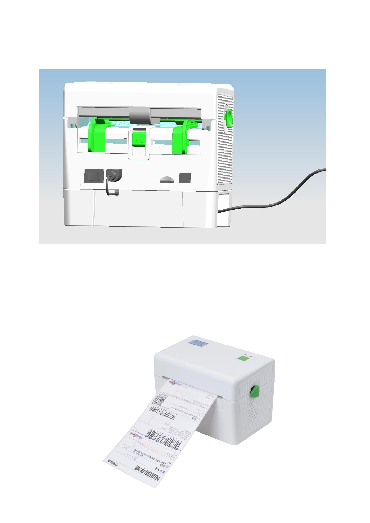
2.2.2 Rear view ................................................................................................................................... 5
3. install ........................................................................................................................................................ 6
3.1 install a printer................................................................................................................................. 6
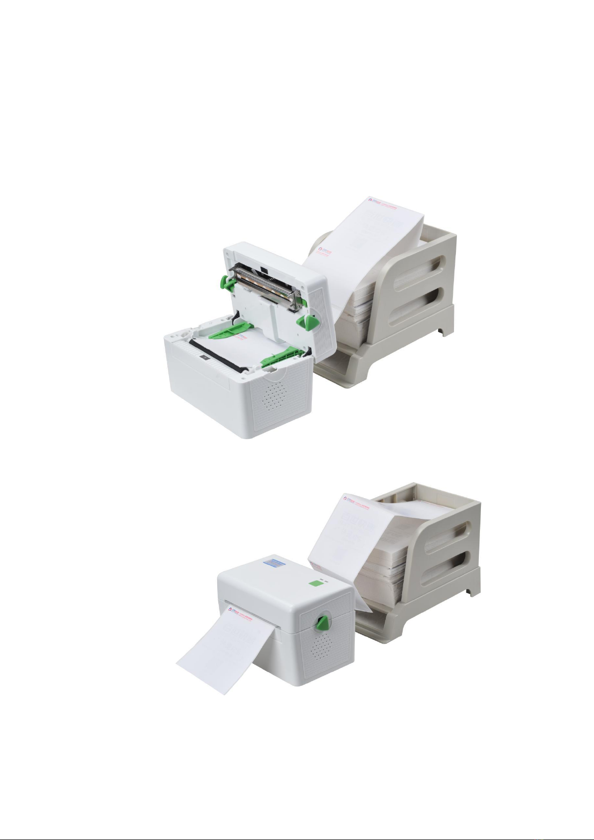
3.2 Mounting sheet ............................................................................................................................... 7
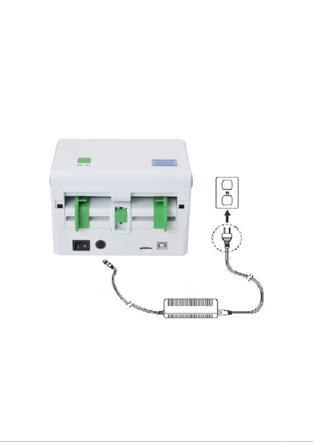
3.3 Built in power supply...................................................................................................................... 8
3.4 Single print function..... ................................................................................................................. 8
4. LED indicator and key function ............................................................................................................... 9
4.1 LED Indicator light............................................................................................................................ 9
4.2 General button function ................................................................................................................... 9
4.3 Internal Network Adaper Boot.......................................................................................................... 9
5. Printer diagnostic tool ........................................................................................................................... 16
5.1 Enable printer diagnostic utility ...................................................................................................... 16
5.2 Printer settings .............................................................................................................................. 17
5.3 Correction of paper sensor with printer diagnostic tool ................................................................ 18
6. Trouble shooting ................................................................................................................................. 19
6.1 Common problem ..................................................................................................................... 19
7. Printer simple maintenance ................................................................................................................ 22
Update record.................................................................................................................................. 23

1
Copyright statement
Information in this subject to change without notice and does not represent a
commitment on the part of Zhuhai Hengquan Barcode equipment Co., Ltd,.. No part of
this manual may be reproduced or transmitted in any form by any means, for any
purpose other than the purchaser’s personal use, without the expressed written
permission of Zhuhai Hengquan Barcode equipment Co., Ltd,..
.
警告

2
Matters needing attention
1. printer cover is the fingers and other parts of the body away from the mouth, to avoid
pressure injury.
2.motherboard contains the timer battery RTC if the replacement is not correct there will
be the risk of explosion.
3.please use the battery according to the manufacturer's instructions.

3
1. Product profile
Thank you for purchasing the XP-DT108B thermal barcode printer company. This
desktop printer will provide you with safe, reliable and efficient print quality at a
reasonable price. In a wide range of label format text or graphics to print out. At the
same time, the strong function and easy operation features, is the thermal barcode
printer, the best choice for you.
XP-DT108B thermal printer to provide print mode. The printing speed can be adjusted in
the second 2, 3, 4 and 5 inches. You can use a variety of printing materials, including
paper, paper labels and folding sections. In addition, the printer is commonly used in the
one-dimensional and two-dimensional bar code, a TTF font and eight groups of different
sizes of English font and supports 4 different angle printing direction. Through the
enlarged function, the font can be made to enlarge the change. Therefore, you can
significantly improve the efficiency of label printing in a short time.

4
2.Introduction
The printer industry is specially packaged to resist any possible damage during transit.
However, in view of the printer in transport
On the way may still be unexpected damage, when receiving the printer, please check
the packaging and printer
The. In case of significant damage, please contact the dealer directly to indicate the
extent of the damage. If necessary, please
Keep packaging material in order to mail the printer.
2.1 Unpacking and inventory of parts
When you receive your barcode printer, please be placed in a clean, steady level
desktop, carefully
Packaging material for printer. Do you have the following items:
A printer
CD piece
USB transmission line
Power supply one (built-in power no)
A power cord
Quick installation guide
Factory selection:
Built in power supply
User selection:
Media storage box

5
2.2 Printer component
2.2.1 Front view
2.2.2 Rear view
1.
2.
3.
4.
5.
电源开关
电源供应插座
SD卡槽
USB接口
Note: the picture transmission interface printer will vary according to your purchase type, please
refer to the actual transmission interface specification product catalog.
1
2
3
4
1. Indicator light
2. Paper key
3. Open cover fastening
4. Paper outlet
1 2 3 4
5
1. Power switch
2. Power supply jack
3. SD card slot
4. USB interface
5. Feeder

6
3. Install
3.1 install a printer
1. Place the printer on a smooth surface and verify that the power is turned off.
2. Insert the power cord into the power outlet of the printer and insert the other end into the
AC socket.
Note: when you insert the power cord into the power outlet of the printer, make sure that
the power switch is turned off

7
3.2 Mounting sheet
1. Push forward with both hands on the button to open the printer cover cover.
2. The paper is placed on the surface of Media box. (When Printing)
3. The surface passes through the paper guiding device, and then the surface is pulled
over the rubber roller.
4. Close the printer cover.
Note: to avoid printing quality, please close the printer cover .

8
3.3 Built in power
The power adapter is assembled by the manufacturer to the built-in power box, the
user only needs to connect the power cord to open the switch to be used.
3.4 Single print function
That lack of paper in the printer voice, put into leaflets from the printer feeder, the
printer will automatically continue printing paper suction. In order to achieve single print
function. (in the standby mode, the paper printer is automatically fed to the print
position)

9

10
4. Indicator and key function
This series of aircraft equipped with 2 sets of gear drive motor can handle 300 of
the printer has a button and a light indicator will display three colors, in the light
of different colors or press the button with the power switch, allowing the printer
to start a number of functions, such as: paper, printing machine to suspend
action, sensor, calibration label print printer initialization value, self testing, see
below introduction.
4.1 LED Indicator light
4.2 General button function
1. Feed
When the printer is ready (LED blue fixed), click the buttons, label paper into
the front end of a paper label.
2. Print job timeout
When the printer is in print, clicking on the button causes the printing to
pause. The power indicator light flashes blue. Just click the button to
print the job back to normal
4.3 Internal Adaper Boot
The printer has four boot functions can be used to set or test the printer
hardware. At the same time, press the button in the boot with the lights,
release the button you can start these functions.
Follow these steps to start the boot function:
1. Power off printer.
2. Press and hold the button to open the printer power supply.
3. Release the button as shown in the following table, as shown in the
required function.
LED Indicator color
Explain
Blue (fixed)
Power start, printer on standby to print
Blue (flashing)
The printer is downloading data or the printer is paused
Purple
Printer is clearing data
Red (fixed)
Upper cover open
Red (flashing)
Print error, for example: the paper, cardboard or run out of
memory errors... Etc.

11
4.3.1 Gap sensor detection
This measurement is used to determine the sensitivity of the label paper
sensor after the printer is turned on (Sensitivity). When the user replacement of
different specifications of the roll or the printer will initialize (Initialization) reduced
the set values for the factory set value, namely the need to re label paper
determination of gap sensor. To detect the gap or black marker is in accordance
with the correction of the last time you set value. The default value of this printer
sensor is set to the gap correction.
Follow these steps:
1. Power off the printer
2. Press the key to open the printer power supply
3. In the first light purple, red flashing, release the feed key
Indicator color cycle mode:
Blue and purple Blue Blue and purple Red(flashing 5 times) Blue
and purple(flashing 5 times) Blue(flashing 5 times) Blue
(fixed)
Be careful:
Please select gap or black mark sensor by GAP command prior to calibrate
the sensor.
For more information about GAP command, please refer to programming
manual.
Internal Network Adaper Boot
Indicator color cycle mode:
Indicator light
function
Blue and
purple
Blue
Blue and
purple
Red
Blue and
purple
Blue
Blue
(flashing 5
times)
(flashing 5
times)
(flashing 5
times)
fixed
1.Gap sensor detection
Release
button
2. The gap sensor detects, print and enter
the value of self testing debugging mode
Release
button
3. Printer initialization (restore factory
defaults)
Release
button
4. Skip
AUTO.BAS
program
Release
button

12
4.3.2 The gap sensor detection; print debugging mode and enter the value of
Self testing
This measurement is used to determine the sensitivity of the label paper sensor
after the printer is turned on. When the user replacement of different
specifications of the roll or the printer will initialize the set values for the restore
factory settings, namely the need to re label paper determination of gap sensor.
To detect the gap or black marker is in accordance with the correction of the last
time you set value. The default value of this printer sensor is set to the gap
correction.
Please follow the steps below to make the calibration of the label paper:
1. Please make sure that the label paper is properly installed
2. Power off the printer
3. Press the key to open the printer power supply
4. In the first light purple, blue and purple, flashing, release the feed key
Indicator color cycle mode:
Blue and purple Blue Blue and purple Red(flashing 5 times) Blue
and purple(flashing 5 times) Blue(flashing 5 times) Blue
(fixed)
5. The sensor will do to correct the label paper, and print from the
measured value, the last into the debug mode and print out the numerical
6. Please turn off the computer again, so that the printer returns to the
normal print mode
Caution:
Before making the label paper sensor calibration, use the Diagnostic Tool or
the GAP command to confirm the type of tag to be detected;More instruction
information about GAP,Please refer to XPL programming manual(Instruction
set manual)

13
Self Test
When the sensor is completed, the printer prints the test value. Before you
connect your printer to your computer, you can use the self test method to verify
that the printer is functioning properly. Print the value of print quality self testing
can be used to check the print head and understand the internal state of this
printer set.
The internal self testing mode set value of print printer
Aircraft type & firmware version
Machine serial number
The print head number range
Check code
Serial setting
character set
Country code
Print speed
Print density
Paper size (width, height)
Gap size (vertical gap, offset)
Sensor strength
Save file information
Print head view

14
Dump mode
When executing the self test after printing, the printer system will enter debug
mode. In debug mode in all volume will be printed out the machine code. The
ASCII string on the left is the data received by the system. While the data is from
the left side of the string of sixteen hexadecimal value printed out. This function is
to provide the user or engineer to debug. You only need to shut off the power to
jump off the back to the normal print mode debugging mode.
ASCII string
The following ASCII
string corresponding
to sixteen
hexadecimal value
data

15
Caution:
1. Data debugging mode print all need 4 "wide label paper
2. Shut off the power to jump off the debug mode, return to normal print mode or
press the FEED button to return to the standby state
4.3.3 Printer initialization
The printer initialization function is to clear the memory (DRAM) download files,
and print parameters to restore the factory settings.
Please do the following steps:
1. Power off
2. Press the paper key and turn on the power. The power indicator below color
cycle
Indicator color cycle mode:
Blue and purple Blue Blue and purple Red(flashing 5 times) Blue and
purple(flashing 5 times) Blue(flashing 5 times) Blue
(fixed)
3. When the power indicator is blue flashing release paper key will reset the
printer, then the power indicator will flash a purple, finally the power indicator is
blue ready state.
The printer configuration will be restored to the default after initialization:
parameter
Default value
speed
101.6 mm/sec (4 ips) (203DPI)
76 mm/sec (3 ips) (300DPI)
concentration
8
Label width
4” (100 mm)
Label height
7.9” (180 mm)
Sensor type
Gap sensor
Gap setting
0.16” (4.0 mm)
Print direction
0
reference point
0,0 (upper left corner)
Offset
0
Tear-off mode
On
character
850
Country code
001
Clear Flash
No
IP address
DHCP

16
4.3.4 Skip AUTO.BAS program
The XPL command language allows the user to load an automatic executable
file (AUTO.BAS) in the flash memory. When the printer is turned on, it will be
executed automatically according to the user loaded file. When you want to boot
after the AUTO.BAS boot, you can use this power to ignore the function of the
automatic implementation of the file.
Please skip AUTO.BAS according to the following steps:
1. Power off。
2. Press the paper key and turn on the power. The power indicator below color
cycle
Indicator color cycle mode:
Blue and purple Blue Blue and purple Red(flashing 5 times) Blue and
purple(flashing 5 times) Blue(flashing 5 times) Blue
(fixed)
3. Release the FEED key when the indicator light is fixed。
4. The printer will skip the AUTO.BAS program。

17
5. Printer diagnostic tool(Diagnostic Tool)
DiagnosticTool is a simple operation of the window tool program, through the
program can view the current state of the printer and set value. According to
the needs of customers can be graphics files, procedures, font files...
Download and firmware update. Another support for dot matrix word
production and download, instruction or file transfer... With this tool,
customers can easily set up the printer, view the status of the printer and
then eliminate the use of printer problems.
5.1 Enable Diagnostic Tool tools
1. Move the mouse cursor to the image, double-click the left mouse
button. 。
2. Open the main screen can be seen in 3 management pages (printer
settings, file management, communication tools)。
Features tab
Pinter Status
Interface
Printer setup

18
5.2 Printer settings
1. Select the connection interface between the computer and the printer.
The default communication interface for this
printer diagnostic utility program is USB, so
if you are using a USB line to connect the
computer to the transmission, this part does
not have to change its settings
2. He pressed the "printer" in the function setup。
3. The printer features in the printer settings management page are as follows。
Function
Description
Calibrate Sensor
Calibrate the sensor specified in the Printer
Setup group media sensor field
Ethernet Setup
Setup the IP address, subnet mask, gateway
for the on board Ethernet (Please refer to next
section)
RTC Time
Synchronize printer Real Time Clock with PC
Factory Default
Initialize the printer and restore the settings to
factory default.
Reset Printer
Reboot printer
Print Test Page
Print a test page
Configuration Page
Print printer configuration
Dump Text
To activate the printer dump mode.
Ignore AUTO.BAS
Ignore the downloaded AUTO.BAS program
Password Setup
Set Printer password when used.
Table of contents
Popular Barcode Reader manuals by other brands

3nStar
3nStar SC365 Technical manual

Cognex
Cognex DataMan DT150 Quick reference guide

Infinite Peripherals
Infinite Peripherals ScanPro BlackBerry user manual

Datalogic
Datalogic DS1100 SH2347 Reference manual

Mindeo
Mindeo CS2190 quick guide

Infinite Peripherals
Infinite Peripherals Infinea Tab 2 Series user manual