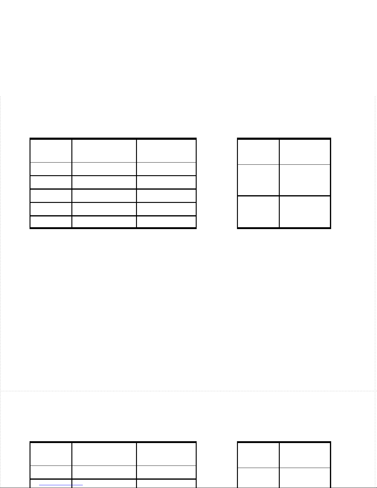
manuals.online logo
Brands
  1. Home
  2. •
  3. Brands
  4. •
  5. Barksdale
  6. •
  7. Switch
  8. •
  9. Barksdale CSK Service manual

Barksdale CSK Service manual

INSTALLATION INSTRUCTIONS - CSK
INSTALLATION NOTES:
Please check the model designation of the pressure switch to ensure it is being
used within its design range. The use of an incorrect switch may cause inad-
vertent operation or failure. Operating, maintenance, inspection and installa-
tion personnel must be qualified to carry out their respective duties. Refer to the
table at the back for switch specifications and adjustment procedures.
ELECTRICAL CONNECTION:
The switch should be wired in accordance with the tables below.
CONTACTS FREE
LEADS
1/4 SPADE
TERMINALS
DEUTSCH
(RECEPTACLE)
COMMON BLACK 1PIN 1
NORMALLY
OPEN BLACK 2PIN 2
NORMALLY
CLOSED BLACK 2PIN 2
Wire / Connector Termination
PRESSURE
MODEL
PRESSURE RANGE
PSI (BAR)
PROOF PRESSURE
PSI (BAR)
220 - 120 (1.4 - 8.3) 9000 (600)
390 - 250 (6.2 - 17.2) 9000 (600)
4250 - 950 (17.2 - 65.5) 9000 (600)
5700 - 1900 (48.3 - 131) 9000 (600)
61000 - 3000 (69 - 207) 9000 (600)
OPERATING CHARACTERISTICS ELECTRICAL RATINGS
SET POINT ADJUSTMENT:
The switch is factory set at approximately 50% of the maximum pressure range.
In order to change the setting of the switch follow the instructions below.
Caution: The adjustment screw is electrically conductive to the contacts. Therefore, to prevent an electric shock,
always use insulated tools and only monitor the circuit with a digital multimeter or low voltage (<12 VDC) LED light
while adjusting the setpoints. Never contact any conductive object, wire, cable, connector pin, or terminal blade
with a conductive portion of the adjusting tool while adjusting the switch.
Step 1: Insert a 1/8” allen key through the opening on the top center of the switch.
Step 2: Turn the allen key clockwise to increase the pressure setting and counter-
clockwise to decrease.
Note: If your product contains flying leads, you will have to remove the two pan Phillip head screw on the top of
the switch and remove the cap in order to access the
adjustment screw.
Caution: Failure to replace the adjustment screw cap will expose the user to the electrically live
adjustment screw Rev 6
ELECTRICAL RATINGS
1
8A @ 12VDC
4A @ 24VDC
2A @ 42VDC
2
33mA @ 12VDC
16mA @ 24VDC
13mA @ 30VDC
GOLD CONTACT

Other Barksdale Switch manuals

Barksdale 9000 Series User manual

Barksdale

Barksdale 9000 Series User manual

Barksdale BLS3000 User manual

Barksdale

Barksdale BLS3000 User manual

Barksdale Dynalco SST7200 User manual

Barksdale

Barksdale Dynalco SST7200 User manual

Barksdale KD1 Series User manual

Barksdale

Barksdale KD1 Series User manual

Barksdale ML1H User manual

Barksdale

Barksdale ML1H User manual

Barksdale UDS 7 User manual

Barksdale

Barksdale UDS 7 User manual

Barksdale UNS1000 User manual

Barksdale

Barksdale UNS1000 User manual

Barksdale D1T User manual

Barksdale

Barksdale D1T User manual

Barksdale UDS 3 User manual

Barksdale

Barksdale UDS 3 User manual

Barksdale 9671 Series User manual

Barksdale

Barksdale 9671 Series User manual

Barksdale CSP Service manual

Barksdale

Barksdale CSP Service manual

Barksdale BPS3000 User manual

Barksdale

Barksdale BPS3000 User manual

Barksdale BDS3000 User manual

Barksdale

Barksdale BDS3000 User manual

Barksdale TempSwitch 2000 User manual

Barksdale

Barksdale TempSwitch 2000 User manual

Barksdale UDS7-BX Installation manual

Barksdale

Barksdale UDS7-BX Installation manual

Barksdale BDS3000 User manual

Barksdale

Barksdale BDS3000 User manual

Barksdale UNS-RG-040 User manual

Barksdale

Barksdale UNS-RG-040 User manual

Barksdale 8000 Series User manual

Barksdale

Barksdale 8000 Series User manual

Popular Switch manuals by other brands

Extron electronics Matrix 12800 Series Specification sheet

Extron electronics

Extron electronics Matrix 12800 Series Specification sheet

Pepperl+Fuchs Vibracon LVL-B1 technical information

Pepperl+Fuchs

Pepperl+Fuchs Vibracon LVL-B1 technical information

Allied Telesis GS980EM Series installation guide

Allied Telesis

Allied Telesis GS980EM Series installation guide

Eneo DS-4 installation instructions

Eneo

Eneo DS-4 installation instructions

Illumra ZBT-S1AWH quick start guide

Illumra

Illumra ZBT-S1AWH quick start guide

McDATA 316095-B21 - StorageWorks Edge Switch 2/24 user manual

McDATA

McDATA 316095-B21 - StorageWorks Edge Switch 2/24 user manual

Endress+Hauser FTE30 manual

Endress+Hauser

Endress+Hauser FTE30 manual

Brocade Communications Systems 5300 Replacement manual

Brocade Communications Systems

Brocade Communications Systems 5300 Replacement manual

Brocade Communications Systems A7533A - Brocade 4Gb SAN Switch Base Administrator's guide

Brocade Communications Systems

Brocade Communications Systems A7533A - Brocade 4Gb SAN Switch Base Administrator's guide

Dungs GGW A4-U/2 X Series Operation and assembly instructions

Dungs

Dungs GGW A4-U/2 X Series Operation and assembly instructions

BEP 720-MDO-EP Operation and installation manual

BEP

BEP 720-MDO-EP Operation and installation manual

HDanywhere MHUB862U40 manual

HDanywhere

HDanywhere MHUB862U40 manual

Key Digital KD-2x1CSK operating instructions

Key Digital

Key Digital KD-2x1CSK operating instructions

FUTABA ESW-2J instruction manual

FUTABA

FUTABA ESW-2J instruction manual

PTN WVG2A user manual

PTN

PTN WVG2A user manual

PCB Piezotronics IMI SENSORS 685B0000A10 Installation and operating manual

PCB Piezotronics

PCB Piezotronics IMI SENSORS 685B0000A10 Installation and operating manual

SPROLINK NeoLIVE R2 PLUS user manual

SPROLINK

SPROLINK NeoLIVE R2 PLUS user manual

ANTAIRA LNX-800AG Hardware manual

ANTAIRA

ANTAIRA LNX-800AG Hardware manual

manuals.online logo
manuals.online logoBrands
  • About & Mission
  • Contact us
  • Privacy Policy
  • Terms and Conditions

Copyright 2025 Manuals.Online. All Rights Reserved.