Checking the dry side - switch body
1. Unscrew the casing top.
2. Check the gasket.
3. Check the inside of the switch for humidity and corrosion.
Replace corroded parts, if any.
4. Check all screws and clamps for tightness and correct position.
There is no need to remove magnet and micro switch.
5. Check the test knob (if any) for leakage and easy movement.
Mounting the switch after maintenance
1. See “Mounting/ Installation”
Make sure the gasket in the top of the casing is inserted properly into the groove.
The gasket must not be jammed. Check proper positioning of the gasket between level switch
and backing flange.
2. Connect power supply.
3. Check operation of switch.
Removal of electric switch mechanism and replacement of micro switch
1. Switch off power supply.
2. Open casing top and disconnect cable.
3. Unscrew the hexagon socket head cap screws and remove the complete switch mechanism.
4. Check, if necessary clean, the inside of the level switch.
5. Check position and easy movement of the magnet.
6. Loosen the cable on the micro switch.
7. Unscrew the hexagon socket head cap screws on the micro switch and remove the micro
switch.
8. Insert new micro switch and tighten hexagon socket head cap screws, being careful not to
damage the micro switch!
9. Move the magnet to check mechanic switch function on the micro switch.
The mechanic function can be heard as a soft click.
10. Fasten the cable of the micro switch to the wire nut.
11. Reinstall the switch mechanism in reverse order of removal; reconnect the wiring.
12. Insert gasket into the groove and fasten the top of the casing securely.
13. Check cable gland for sealing.
14. Check operation of switch.
8 Principle of Operation
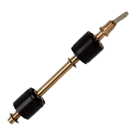
The sturdy gunmetal casing with integrated connection flange is the core part of the switch. The
casing top is sealed by means of an O ring and thus has an IP 56 protection system. The
protection system IP 68 is achieved by factory mounted and shrunken cable as well as with the top
of the casing, which is sticked together.
All components feature high vibration and impact resistance.
Magnetic transmission of the float position to the switch mechanism is effected without any ducts.
The magnet works according to the repulsion principle and thus effects an abrupt, positive
switching function. Appropriate assignment of the micro switch enables transmission of plant-
specific control commands (level-dependent) to pumps, solenoid valves or switching relays.
The magnet is integrated in the actuating element and completely welded with the float to one unit.
Float, axle, test knob (optional) and threaded plug are completely made of 1.4571 and thus
corrosion-resistant and of long service life. The O ring in the test knob features high pressure
resistance and allows testing of the switch function also during operation.
Conversion to an EEx device can be effected without dismounting the device.
IMPORTANT
When a perforated disk is used (-LS) on the float unit the switching hysteresis can be limited.
9 Technical Data
Materials
- casing
- float unit
- flat packing
- rubber gasket
RG5, RG10 (gunmetal)
1.4571
oil and saltwater-proof
EPDM, NPR
System of protection IP56 / IP68 (cable type)
Approvals EEx d IIC T6 accord. to ATEX
Max. pressure 42 bar for float
Min. density 0.46 g / cm3
Max. temperature
- ambient temperature
- ambient temperature for
EEx d approval
-40 °C ... +125 °C
-40 °C ... +82 °C
Installation position from top, lateral
Electrical connection screwed cable gland M20 x 1.5 mm
Contact type change-over contact (WE)
Weight 3.5 kg approx.
6 7


