Barnstead International General Purpose Aquabath 18002 User manual

General Purpose Aquabaths™
Model No.
Digital Water Baths: Basic Water Baths:
18002, 18002-1CE 18000, 18000-1
18007, 18007-1CE 18005, 18005-1
18012, 18012-1CE 18010, 18010-1
18022, 18022-1CE 18020, 18020-1
18052, 18052-1CE 18050, 18050-1
18102, 18102-1CE 18100, 18100-1
18802, 18802-1CE 18800, 18800-1
18902, 18902-1CE 18900, 18900-1
Teflon® Coated:
18202, 18202-1CE
18212, 18212-1CE
057-533-00 • 7/21/05

2
Safety Information ........................................................................................................................................................3
Alert Signals ..........................................................................................................................................................3
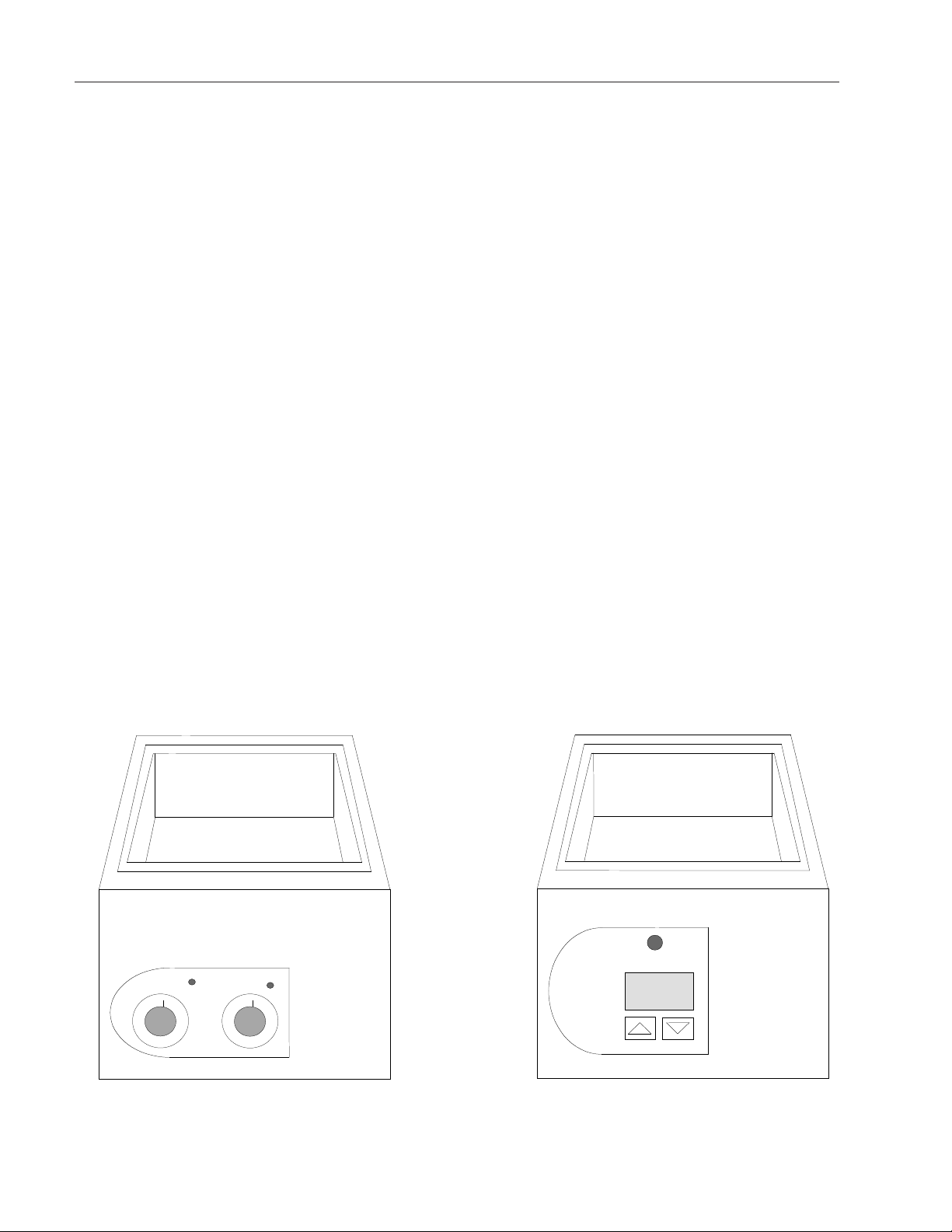
Description....................................................................................................................................................................4
Specifications .............................................................................................................................................................. 5
Digital Water Baths ................................................................................................................................................5
Electrical Requirements..................................................................................................................................5
Temperature Range ........................................................................................................................................5
Uniformity ...................................................................................................................................................... 5
Control .......................................................................................................................................................... 5
Basic Water Baths ................................................................................................................................................5
Electrical Requirements..................................................................................................................................5
Temperature Range ........................................................................................................................................5
Uniformity ...................................................................................................................................................... 5
Control .......................................................................................................................................................... 5
Tank Capacity and Dimensions Digital Water Baths ............................................................................................6
Tank Capacity and Dimensions Basic Water Baths ..............................................................................................7
Declaration of Conformity ......................................................................................................................................8
Unit’s Environmental Operating Conditions ..........................................................................................................8
Unpacking and Installation ..........................................................................................................................................9
Electrical Requirements ........................................................................................................................................9
Setup ....................................................................................................................................................................9
Operation....................................................................................................................................................................10
Controls, Digital Water Baths ..............................................................................................................................10
Bath Temperature is Maintained by Microprocessor Controller ..........................................................................11
Setting the Temperature, Digital Water Baths......................................................................................................11
Temperature Calibration, Digital Water Baths......................................................................................................11
Controls-Basic Water Baths ................................................................................................................................12
Water Bath Temperature is Regulated by Two Thermostats ..............................................................................12
Setting the Temperature, Basic Water Baths ......................................................................................................13
Models 18020 and 18020-1 ................................................................................................................................13
Maintenance ..............................................................................................................................................................14
Draining the Tank ................................................................................................................................................14
Routine Tank Cleaning ........................................................................................................................................14
The Alloy Called Stainless ..................................................................................................................................14
Some Stainless Guidelines to Consider ..............................................................................................................15
The pH Factor......................................................................................................................................................15
Special Considerations........................................................................................................................................15
Cleansing Agents ................................................................................................................................................16
Cleaning Methods................................................................................................................................................16
Materials Effective in Disinfecting........................................................................................................................17
Refilling the Tank ................................................................................................................................................17
Troubleshooting ..........................................................................................................................................................18
Over Temperature Protection ..............................................................................................................................18
Replacement Parts ....................................................................................................................................................19
Ordering Procedures ..................................................................................................................................................21
Two Year Limited Warranty ........................................................................................................................................24
Table of Contents

3
Read operation manual before using equipment to famil-
iarize yourself the controls and accessories.
When operating this equipment, always wear protective
clothing, glasses and other accessories as specified by
the safety regulations of your organization.
We recommend that you do not leave equipment unat-
tended while it is in operation. Do not operate equipment
with a damaged electrical cord or allow cord to come into
contact with a hot surface. Do not operate equipment in
an explosive atmosphere. Do not insert fingers into
equipment when it is operating.
Do not modify construction and/or assembly of equip-
ment. Keep guards in place. Do not remove tags, labels,
decals or other information from the unit.
To eliminate hazard of electrical shock, make sure floor
around machine is dry in the event of accidental spilling
or splashing of liquids, clean up and/or neutralize the
spilled liquids before continuing.
Do not use equipment for other than its intended purpose.
Use only the accessories and attachments that are
shipped with the equipment or are specified for it. Other
accessories can produce hazards or make the unit inop-
erative.
Perform regular maintenance service as specified in this
manual and keep unit in good repair. Do not operate with
known defects. Always disconnect equipment from power
source before servicing or performing any maintenance
procedures.
Safety Information
Warning
Warnings alert you to a possibility of
personal injury.
Caution
Cautions alert you to a possibility of
damage to the equipment.
Note
Notes alert you to pertinent facts and
conditions.
Hot Surface
Hot surfaces alert you to a possibility of
personal injury if you come in contact
with a surface during use or for a period
of time after use.
Alert Signals

4
Description
The Barnstead|Lab-Line General Purpose Aquabaths are
designed for use in clinical research labs, pharmaceutical
labs and a multitude of chemical, biological, research and
industrial laboratory applications. They are ideal for sero-
logical studies and numerous other applications requiring
accurate temperature control. Special heaters positioned
beneath the bath chamber transfer heat efficiently. The
stainless steel diffuser plate on the chamber bottom helps
distribute the heat uniformly and provides a level surface
for a variety of glassware. Its removal adds an extra inch
of depth to the bath.
Heat is controlled from slightly above ambient to
65ºC (100ºC with cover) with uniformity of ±0.2ºC.
Depending on the model, temperature is maintained in
one of two ways:
•with microprocessor temperature controller,
•with dual hydraulic thermostats.
The bath chamber is constructed of seamless stainless
steel and has rounded corners with no perforations. This
allows easy cleaning and eliminates the possibility of
water leakage onto electrical components.
Basic Water Bath Digital Water Bath

5
Digital Water Baths
Electrical Requirements
18002: 120V 50/60 Hz 500W
18002-1CE: 240V 50/60 Hz 500W
18007: 120V 50/60 Hz 1000W
18007-1CE: 240V 50/60 Hz 1000W
18012: 120V 50/60 Hz 1500W
18012-1CE: 240V 50/60 Hz 1500W
18022: 120V 50/50 Hz 300W
18022-1CE: 240V 50/60 Hz 300W
18052: 120V 50/60 Hz 300W
18052-1CE: 240V 50/60 Hz 300W
18102: 120V 50/60 Hz 1500W
18102-1CE: 240V 50/60 Hz 1500W
18202: 120V 50/60 Hz 1000W
18202-1CE: 240V 50/60 Hz 1000W
18212: 120V 50/60 Hz 1500W
18212-1CE: 240V 50/60 Hz 1500W
18802: 120V 50/60 Hz 1500W
18802-1CE: 240V 50/60 Hz 1500W
18902: 120V 50/60 Hz 1000W
18902-1CE: 240V 50/60 Hz 1000W
Temperature Range
Slightly above ambient to 100ºC with cover
(included as standard equipment)
Slightly above ambient to 65ºC without cover
Uniformity
±0.2ºC
Control
±0.15ºC
Specifications
Basic Water Baths
Electrical Requirements
18000: 120V 50/60 Hz 500W
18000-1: 240V 50/60 Hz 500W
18005: 120V 50/60 Hz 1000W
18005-1: 240V 50/60 Hz 1000W
18010: 120V 50/60 Hz 2000W
18010-1: 240V 50/60 Hz 2000W
18020: 120V 50/60 Hz 300W
18020-1: 240V 50/60 Hz 300W
18050: 120V 50/60 Hz 300W
18050-1: 240V 50/60 Hz 300W
18100: 120V 50/60 Hz 1500W
18100-1: 240V 50/60 Hz 1500W
18800: 120V 50/60 Hz 1500W
18800-1: 240V 50/60 Hz 1500W
18900: 120V 50/60 Hz 1000W
18900-1: 240V 50/60 Hz 1000W
Temperature Range
Slightly above ambient to 100ºC with cover
(included as standard equipment)
Slightly above ambient to 65ºC without cover
Uniformity
±0.2°C
Control
±0.5°C

Tank Capacity and Dimensions Digital Water Baths
(applies to both 120V and 240V units)
Model Liters Interior (cm) Exterior (cm)
18002 & 6.7 5-7/8" W x 11-5/8" D x 5" H 8-3/8" W x 14" D x 9" H
18002-1CE: (15 x 30 x 13) (21 x 36 x 23)
18007 & 14.6 12-3/4" W x 11-5/8" D x 5" H 14" W x 15" D x 9" H
18202*: (32 x 30 x 13) (36 x 38 x 23)
18012 & 44.0 28” W x 16” D x 6” H 31-5/8” W x 19-5/8” D x 9” H
18012-1CE: (71 x 41 x 15) (80 x 50 x 23)
18022 & 2.0 5-7/8” W x 11-5/8” D x 2-1/2” H 7-1/2” W x 14-1/2” D x 7” H
18022-1CE: (15 x 30 x 6) (19 x 37 x 18)
18052 & 3.1 5-7/8” W x 5-3/8” D x 5” H 8-3/8” W x 7-7/8” D x 9” H
18052-1CE: (15 x 14 x 13) (21 x 20 x 23)
18102 & 22.0 11-5/8” W x 19-1/2” D x 5” H 13-3/8” W x 21-1/4” D x 9” H
18212*: (30 x 50 x 13) (34 x 54 x 23)
18802: 6.7 5-7/8” W x 11-5/8” D x 5” H 23-1/4” W x 14-1/4” D x 9” H
(Sm. bath) (15 x 30 x 13) (59 x 36 x 23)
18802-1CE: 14.6 12-3/4” W x 11-5/8” D x 5” H 23-1/4” W x 14-1/4” D x 9” H
(Lg. bath) (32 x 30 x 13) (59 x 36 x 23)
18902 & 33.0 14” W x 12” D x 11” H 16-3/8” W x 16-3/8” D x 12” H
18902-1CE: (36 x 30 x 28) (42 x 42 x 30)
6
SPECIFICATIONS
*Models 18202 and 18202-1CE are identical to 18007 and 18007-1CE with the exception that the baths are
teflon coated; additionally, 18212 and 18212-1CE are identical to 18102 and 18102-1CE in the same manner.

Tank Capacity and Dimensions Basic Water Baths
Model Liters Interior (cm) Exterior (cm)
18000 & 6.7 5-7/8” W x 11-5/8” D x 5” H 8-3/8” W x 14” D x 9” H
18000-1: (15 x 30 x 13) (21 x 36 x 23)
18005 & 14.6 12-3/4” W x 11-5/8” D x 5” H 14” W x 15” D x 9” H
18005-1: (32 x 30 x 13) (36 x 38 x 23)
18010 & 44.0 28” W x 16” D x 6” H 31-5/8” W x 19-5/8” D x 9” H
18010-1: (71 x 41 x 15) (80 x 50 x 23)
18020 & 2.0 5-7/8” W x 11-5/8” D x 2-1/2” H 7-1/2” W x 14-1/2” D x 7” H
18020-1: (15 x 30 x 6) (19 x 37 x 18)
18050 & 3.1 5-7/8” W x 5-3/8” D x 5” H 8-3/8” W x 7-7/8” D x 9” H
18050-1: (15 x 14 x 13) (21 x 20 x 23)
18100 & 22.0 11-5/8” W x 19-1/2” D x 5” H 13-3/8” W x 21-1/4” D x 9” H
18100-1: (30 x 50 x 13) (34 x 54 x 23)
18800: 6.7 5-7/8” W x 11-5/8” D x 5” H 23-1/4” W x 14-1/4” D x 9” H
(Sm. bath) (15 x 30 x 13) (59 x 36 x 23)
18800-1: 14.6 12-3/4” W x 11-5/8” D x 5” H 23-1/4” W x 14-1/4” D x 9” H
(Lg. bath) (32 x 30 x 13) (59 x 36 x 23)
18900 & 33.0 14” W x 12” D x 11” H 16-3/8” W x 16-3/8” D x 12” H
18900-1: (36 x 30 x 28) (42 x 42 x 30)
7
SPECIFICATIONS

Declaration of Conformity
(for 220-240 volt, CE models only)
Barnstead International hereby declares under its sole responsibility that this product conforms with the tech-
nical requirements of the following standards:
EMC: EN 61000-3-2 Limits for harmonic current emissions
EN 61000-3-3 Limits for voltage fluctuations and flicker
EN 61326-1 Electrical equipment for measurement, control, and laboratory use; Part l:
General Requirements
Safety: EN 61010-1 Safety requirements for electrical equipment for measurement, control, and
laboratory use; Part I: General Requirements
EN 61010-2-010 Part II: Particular requirements for laboratory equipment for the heating of
materials
per the provisions of the Electromagnetic Compatibility Directive 89/336/EEC, as amended by 92/31/EEC and
93/68/EEC, and per the provisions of the Low Voltage Directive 73/23/EEC, as amended by 93/68/EEC.
The authorized representative located within the European Community is:
Electrothermal Engineering Ltd.
419 Sutton Road
Southend On Sea
Essex SS2 5PH
United Kingdom
Copies of the Declaration of Conformity are available upon request.
8
SPECIFICATIONS
Unit's Environmental Operating Conditions
Pollution Degree*: 2
Installation Category*: II
Altitude: 2000 Meters MSL (Mean Sea Level)
Humidity: 80% maximum, non-condensing
Electrical Supply: 120VAC or 240VAC
Voltage Tolerance: ±10% of normal rated line
Temperature: 15ºC to 40ºC
Product Usage: This product is intended for use indoors only
*Refer to IEC 664-1

9
Unpacking and Installation
Electrical Requirements
120 VAC models require a 120 VAC, 50/60 Hz power
source. They are supplied with a 3-wire line cord. It
should be plugged into an outlet designed for 3-prong
plugs. If an extension cord is used, it also should be the
3-wire grounded type. For an outlet designed to accept
2-prong plugs (ungrounded), it is required that a qualified
electrician replace the outlet with a new grounded type.
240 VAC models require a 240 VAC, 50/60 Hz power
source. Because of the variety of plug configurations in
use worldwide for 240 VAC power, the unit may be fur-
nished with the plug removed. The user must install a
plug to conform with local code and configuration require-
ments.
If a plug must be installed, use only the 3-prong grounded
type, rated for the unit load requirements and matching
the power outlet. Make sure the green ground wire is
secured to the plug ground terminal.
Setup
Place the water bath on the table or bench where it is to
be operated.
It should be in a level position, though this is not neces-
sary for the operation of the unit. Additionally, it should be
out of direct drafts unless a gable cover is used.
Fill the water compartment with water, preferably distilled
or chemically softened, to the desired level.
Move the power switch to the OFF position and plug the
power cord into required outlet.
Note
Leave unit disconnected when not in
use.
Caution
Do not operate the unit without water
in the water compartment. To do so
may result in damage to the heaters.

10
Controls, Digital Water Baths
1. Temperature Status Lamp (Amber)
2. LED Temperature Display
3. Power Switch (OFF/ON)
4. UP Arrow Key
5. DOWN Arrow Key
Operation
Warning
Do not use in the presence of flamma-
ble or combustible materials or explo-
sive gases. Fire or explosion may
result causing death or severe injury.
Warning
Do not heat any substance above a
temperature that will cause it to emit
toxic fumes. Death or severe injury
may result.
Warning
At higher temperatures the exterior of
the bath becomes warm to the touch.
Do not touch these surfaces.
Warning
Do not operate the unit if any of the
temperature controls become inopera-
tive; a hazardous condition will devel-
op which can result in injury or death
and property damage.
Temperature °C
Power
5
3
1
2
4

11
Bath Temperature is Maintained
by Microprocessor Controller
The control panel consists of a microprocessor temperature
controller, LED temperature readout, power switch and one
pilot light that indicate heater is operational.
Setting the Temperature, Digital
Water Baths
•Turn the power switch ON. The display will flash
the current revision number for about 5 seconds,
then the temperature will be displayed.
•Press and release either the UP or DOWN
ARROW KEY once. The display will flash the
existing setpoint temperature already established.
•To change a temperature setpoint, press the
appropriate UP or DOWN key to raise or lower
the temperature to a desired value and release.
When the displayed temperature stops flashing-
showing the actual temperature of the water at
the moment. The new setpoint is established.
Temperature Calibration, Digital
Water Baths
•Place a thermometer in the approximate geomet-
ric center of the water pan; allow at least 1 full
hour for the temperature to stabilize.
•Press and hold both the UP and DOWN ARROW
KEYS together at the same time until the display
begins to flash a left and right decimal point.
•Check the thermometer to see if the display tem-
perature matches the thermometer temperature.
•If the displayed temperature does not match the
thermometer reading, press the appropriate UP or
DOWN ARROW KEY to adjust the displayed tem-
perature to match the thermometer temperature.
Upon releasing the ARROW KEY, the display will
stop flashing and the displayed temperature will
match the thermometer temperature. Calibration
data is automatically entered and stored.
OPERATION
Note
If the up or down arrow keys are not
touched for 5 seconds the display will
default to the actual temperature.

12
Controls-Basic Water Baths
1. Control Panel Status Lamp (Amber)
2. Control Thermostat
3. Hi-Limit Status Lamp (Red)
Water Bath Temperature is
Regulated by Two Thermostats
The control panel consists of two thermostats (control and
high limit) and two pilot lights that indicate which thermo-
stat is controlling temperature. The dials have a graduat-
ed scale that is used for reference only.
OPERATION
1
24
3
0
2
46
8
10 10
8
6
4
2
0
Control High Limit

Setting the Temperature, Basic
Water Baths
•To set the bath temperature:
•Turn the power switch ON.
•Rotate the high limit knob clockwise to its maxi-
mum setting.
•Rotate the control thermostat to an approximate
desired setting. Allow time for temperature of
bath to stabilize. Several minor adjustments of
the control thermostat will have to be made
before reaching the desired temperature.
However, always allow plenty of time between
adjustments to assure temperature stabilization.
•After the desired temperature has been attained
and stabilized, the high limit thermostat must be
set properly to prevent an over-temperature con-
dition, if the control thermostat should ever fail.
The amber status lamp (heating) will always
cycle ON and OFF at any given temperature
setting. The setting of the high limit thermostat
must be made during that period of the ON-OFF
cycle when the amber heat status lamp is on.
With the lamp ON, rotate the high limit thermo-
stat from its full clockwise direction slowly coun-
terclockwise until the point where the amber sta-
tus lamp goes out and the red hi-limit status
lamp goes ON. Rotate the high limit thermostat
knob clockwise a slight amount, representative
of about 2 or 3 degrees higher than the control
knob setting. Should the control thermostat
ever fail, the maximum temperature that the
water in the bath will reach is now limited to the
high limit thermostat setting which is approxi-
mately 2º or 3º above the desired temperature
setting.
Models 18020 and 18020-1
These units are designed with a single temperature con-
trol thermostat and a high temperature cutout that is inte-
grated into the circuitry. The high temperature cutout will
be activated in the event of failure of the temperature con-
trol thermostat and will abort power to the heater.
OPERATION
Note
Each time the control thermostat is
reset, there must be an accompanying
adjustment in the high-limit thermo-
stat.
Caution
The high temperature cutout is a non-
resettable device and must be replaced
in the event it has been activated by
control thermostat failure.
13

14
Maintenance
Warning
Disconnect from the power supply
prior to maintenance and servicing.
Note
Make no attempt to service or repair a
Barnstead|Lab-Line product under
warranty before consulting your
Barnstead|Lab-Line dealer. After the
warranty period, such consultation is
still advised, especially when the
repair may be technically sophisticat-
ed or difficult.
If assistance is needed beyond what
the distributor can provide, please call
the Barnstead International customer
service department at 1-800-553-
0039. No merchandise, however
should be returned without prior
approval from Barnstead International.
Properly operated and maintained, the water baths will
provide trouble- free service for a long time.
Draining the Tank
The bath water needs to be drained and replaced periodi-
cally with fresh water. We recommend using a siphon,
siphoning hand pump or a small electric pump to drain
the water.
Routine Tank Cleaning
Clean the tank and components immersed in the bath
with a solution of mild soapy water. Use a sponge, cloth
or synthetic sponge scrubber. Rinse well. Dry thoroughly.
The Alloy Called Stainless
Stainless steel is an alloy of steel with chromium and
nickel that increase the metal's resistance to rust and cor-
rosion. Yet, if not properly cared for, stainless steel can
rust and corrode.
Exposure to air provides the passivation, or oxide layer
coating, for clean stainless by producing a thin, durable
chromium-oxide film that forms rapidly on the alloy sur-
face to give stainless its characteristic "stainless" quality.
Also exposure of the surface to other oxidizing environ-
ments can produce a passivating film or coating.
However, if free oxygen is not available due to scale or
contamination buildup the metal surface may become vul-
nerable to rusting and corrosion as well as pitting. But by
maintaining neutral pH and conducting frequent cleanings
with detergent and water, years of trouble-free service
from stainless steel products can be obtained.
Caution
Electrolysis can damage stainless steel.
This occurs when an object is allowed
to rest directly on the surface of stain-
less steel, trapping moisture that
becomes oxygen-starved, but is sur-
rounded by water-containing oxygen.
Warning
Disconnect unit from power source
prior to cleaning. We recommend all
service be performed by qualified
service personnel.

15
Some Stainless Guidelines to
Consider
Distilled water is recommended. Please note, if this water
is very pure it may be corrosive to stainless. When filling
a bath or incubator, ALWAYS ADD 2 to 40 PPM (20 TO
40 MG/LITER) DISODIUM PHOSPHATE OR SODIUM
BICARBONATE, ADJUSTING DOSAGE TO PROVIDE A
pH VALUE OF 7 TO 9.
If not available, use clean, aerated soft tap water provided
the total solids concentration is < 500 PPM. WE DO NOT
RECOMMEND USING 18 MEG OHM DEIONIZED
WATER. If this is the only source of treated water avail-
able-mix with regular tap water at a 50/50 ratio.
The pH Factor
Check pH regularly. If pH is <6.0, add disodium phos-
phate to increase pH to a 7 to 9 value. Sodium carbonate
or sodium bicarbonate may be used but they tend to form
scale that must be rinsed out regularly. If pH is >10.0,
add sodium bisulfate to decrease pH to a 7 to 9 value.
Avoid adding harsh alkalines or acids since these may
cause localized corrosion and result in unstable pH.
Special Considerations
Chemicals which should be limited to a 3 hour maximum
exposure time to stainless steel are:
Aluminum chloride E.D.T.A.
Potassium permanganate Barium chloride
Ferrous chloride Potassium thiocyanate
Calcium chloride Lysol
Sodium hypochlorite Chlorinated Lime
Mercury salts Stannous chloride
Citric acid (boiling) Phenol
Tartaric acid Dakin's solution
MAINTENANCE
Warning
If it is necessary to use the following
chemicals, limit exposure time to a
maximum of 3 hours-always clean
surfaces immediately after use.

16
MAINTENANCE
BE ADVISED: NEVER USE THE FOLLOWING ON
STAINLESS STEEL:
Aqua regia
Ferric chloride
Iodine
Sodium acid
Sodium azide
Chemical spills, especially those agents listed here,
should be removed as soon as possible and the stainless
steel surface cleaned with mild soapy water followed by a
clean water rinse.
Cleansing Agents
Anti-fungal and anti-bacterial additives are permissible to
use as long as the pH of the aqueous solution is kept
within the range of 7 to 9. These are available through
laboratory distributors-be sure to CONFIRM that they are
not harmful to stainless steel.
Do not use any metallic pads. Instead, for stubborn
stains, use a plastic light-duty cleansing pad and rub
GENTLY in the direction of the metal grain.
If stains continue to persist, use one of the following
chemicals and methods.
Cleaning Methods
•Any of a variety of "scale removers" available at
local supermarkets or hardware stores used for
the cleaning of coffee marks, humidifiers or
vaporizers.
•A15% to 35% phosphoric acid solution avail-
able from laboratory supply distributors for scale
and rust removal. Allow solution to soak the
surface affected until rust and scale is loosened.
Immediately follow with a clean water rinse.
•Citric acid based cleaners.
•Bathroom tub and tile cleaners.
Caution
Extreme care must be taken when
handling these materials. Always
work in an area with adequate ventila-
tion. Use the precautions as outlined
in the material safety data sheet
(MSDS) and the manufacturer's
instructions for the product being uti-
lized. Also, follow the personal protec-
tion index found in the hazardous
materials information system (HMIS)
section of the MSDS.
Note
The use and disposal of these chemi-
cals may be regulated by your local
city codes; consult those regulations
before of disposing of these materials.
Caution
Extreme care must be taken when
handling these materials. Always work
in an area with adequate ventilation.
Use the precautions as outlined in the
material safety data sheet (MSDS)
and the manufacturer's instructions for
the product being utilized. Also, follow
the personal protection index found in
the hazardous materials information
system (HMIS) section of the MSDS.
Note
The use and disposal of these chemi-
cals may be regulated by your local
city codes; consult those regulations
before disposing of these materials.

17
MAINTENANCE
•Amixture of 20% nitric acid and 1.5% hydrofluoric
acid (or hydrochloric acid). Swab solution on sur-
face allowing it to remain until rust is loosened.
Immediately follow with a clean water rise. This
method should ONLY be used if SEVERE rust
and scale stains are present.
•Oxalic acid 2% to 5% in warm water. Swab solu-
tion on surface allowing it to remain until rust is
loosened. Immediately follow with a clean water
rinse. This method should ONLY be used if
SEVERE rust and scale stains are present.
Regardless of the approach utilized, ALWAYS follow the
manufacturer's directions and allow the chemicals to do the
cleaning with MINIMAL scrubbing.
Always follow cleanings with a clean water rinse. Air dry.
Materials Effective in
Disinfecting
•Glutaraldehyde
•Alcohol
BE ADVISED: this information is intended as guidelines
only and Barnstead International makes no claim as to the
suitability to any particular situation. Consult your staff
chemist to determine what would be best for your stainless
steel product and laboratory.
Refilling the Tank
Use DISTILLED only. Do not use tap water-it will cause
mineral deposits to build up. Add a fungicide/bactericide
(not chlorine-based) to the tank to increase the useful life
of the water.

18
The following is intended as a guide to help in servicing this unit, if problems should occur.
Symptom Possible Causes of Problem
Unit is does not operate: Unit is not plugged in or not plugged into proper outlet.
ON/OFF switch is in the OFF position.
Check fuses. Fuse may be blown.
Unit does not heat up: Unit not plugged in or not plugged into proper outlet.
ON/OFF switch is in OFF position.
Faulty heater.
Faulty controller, digital water bath.
Faulty thermostat, basic water bath.
Control thermostat set at 0 basic water bath.
OTP (Overtemperature Protection) has tripped. Reset OTP.
LED reads "EEE" This is not a problem with the LED but the reading that is obtained when
Digital Water Bath: water bath temperature has reached 100ºC.
Over Temperature Protection
In the unlikely event that the programmed hi-limit and the user adjustable hi-limit thermostats fail, there is a
third over temperature thermostat. The thermostat is located underneath the water bath's bottom panel
attached to the pan. If the water bath fails to heat with the "HEAT ON" lamp lit and the user settable hi-limit
thermostat set to the fully clockwise position, it will be necessary to reset the secondary over temperature
thermostat. To do so, proceed as follows:
1. Disconnect power cord from outlet.
2. Drain bath
3. Remove bottom panel.
4. Locate the thermostat underneath insulation. The thermostat has a small button that needs to be pressed
in to reset the thermostat.
5. Once the thermostat is reset, reposition insulation, reinstall the bottom panel, plug the power cord back
into the outlet and verify the unit is heating again.
6. If the water bath still fails to heat, contact Barnstead International customer service for further assistance.
Troubleshooting
Note
Before attempting any repair, disconnect power cord from outlet.

19
Description Part Number
Cordset: 470-105-00
Grommet: 790-247-00
Diffuser Trays:
18022: 593-115-00
18052: 593-114-00
18802 (small), 18002: 593-110-00
18802 (large), 18007: 593-111-00
18102: 593-118-00
18012: 018-824-00
18900, 18902: 584-112-00
18202: 593-111-01
18212: 593-118-01
18020: 592-842-00
18050: 592-843-00
18800, 18000: 592-844-00
18800, 18005: 592-845-00
18100: 592-846-00
18010: 592-847-00
Gable Covers:
18000, 18800, 18002, 18022, 18802 (small), 18020, 18800 (small): 720-428-00
18007, 18800, 18802 (large), 18202, 18005, 18800: 720-429-00
18102, 18212, 18100: 720-432-00
18012, 18010: 720-430-00
18902, 18900: 720-433-00
18050, 18052: 720-433-01
Over-temperature Protection (OTP):
18000, 18000-1, 18005, 18005-1, 18010, 18010-1,
18100, 18100-1, 18800, 18800-1, 18900, 18900-1,
18002, 18002-1CE, 18007, 18007-1CE, 18012, 18012-1CE,
18102, 18102-1CE, 18202, 18202-1CE, 18212, 18212-1CE,
18802, 18002-1CE, 18902, 18902-1CE: 330-400-00
18020, 18020-1, 18022, 18022-1CE,
18050, 18050-1, 18052, 18052-1CE: 330-403-00
Fuses:
5 amp
18000-1, 18020, 18022,18050, 18052, 18002-1, 18002-1CE (2): 330-273-00
10 amp
18000, 18002, 18005-1, (2), 18007-1, 18007-1CE (2), 18100,
18900-1, 18102-1, 18102-1CE (2), 18902-1, 18902-1CE (2): 330-239-00
20 amp
18005, 18007, 18900, 18902,18100, 18102: 330-241-00
15 amp
18010-1 (2), 18800-1, 18802-1, 18802-1CE(2),18012-1, 18012-1CE (2): 330-298-00
20 amp
18010, 18012,18800, 18802: 330-299-00
4 amp
18020-1,18022-1, 18022-1CE, 18050, 18052-1, 18052-1CE: 330-371-00
Replacement Parts

20
Description Part Number
Fuse Holder:
18012, 18012-1, 18012-1CE, 18802, 18802-1, 18802-1CE,
18010, 18010-1, 18010-1CE, 18800, 18800-1, 18800-1CE: 330-297-00
18002: 330-237-00
18000, 18005, 18005-1, 18020, 18050, 18100-1, 18900: 330-273-01
Thermometer Holders:
18010: 592-170-00
18000, 18005, 18020, 18050, 18100,18800, 18900: 592-106-00
Heaters:
120V Units: 340-183-00
240V Units: 340-185-00
18020: 340-331-00
18020-1: 340-326-00
18050, 18052: 340-184-00
18050-1, 18052-1: 340-186-00
High Limit Temperature Cutouts:
18020, 18020-1: 330-261-00
Rubber Feet:
18020, 18050, 18000, 18005, 18900,
18022,18052,18002,18007,18202: 790-214-00
18010, 18100, 18100-1, 18800, 18800-1,
18102,18012,18802,18902,18212: 790-225-00
Status Lamp Base, 120V/240V: 360-233-01
Status Lamp Lens (Red): 360-234-00
Status Lamp, Temperature (Amber): 360-235-00
Thermometer Grommet: 790-247-00
Switch, Power, 120V Units: 440-359-00
Switch, Power, 240V Units: 440-292-00
Temperature Controller, 120V: 485-197-00
Temperature Controller, 240V: 485-404-00
Temperature Sensor, 120-240V: 410-663-00
Thermostats:
18000, 18005, 18010, 18100, 18800,18900: 920-232-00
18020: 920-313-00
18050: 920-301-00
Wiring Diagrams:
18002, 18007, 18012, 18022, 18052, 18102,18902, 18202, 18212: 229-415-00
18802: 229-416-00
18002-1CE, 18007-1CE, 18012-1CE, 18022-1CE,
18052-1CE, 18102-1CE, 18902-1CE, 18202-1CE, 18212-1CE: 229-417-00
18802-1CE: 229-418-00
18000, 18005, 18010, 18050, 18100, 18900: 229-411-00
18800: 229-412-00
18020: 229-409-00
18000-1, 18005-1, 18010-1, 18050-1, 18100-1, 18900-1: 229-413-00
18020-1: 229-410-00
18800-1: 229-414-00
REPLACEMENT PARTS
This manual suits for next models
29
Table of contents
Other Barnstead International Laboratory Equipment manuals

Barnstead International
Barnstead International DIamond 1265 Series User manual

Barnstead International
Barnstead International 379 Series User manual

Barnstead International
Barnstead International Harvey Hydroclave MC8 User manual

Barnstead International
Barnstead International Cimarec series User manual

Barnstead International
Barnstead International Harvey Hydroclave MC8 User manual

Barnstead International
Barnstead International 1085 Series User manual