Barnstead International Harvey Hydroclave MC8 User manual

1
Harvey®
Hydroclave MC8
Hydroclave MC10
Steam Sterilizer
(With Optional Non-Recirculating System)
OWNER AND OPERATOR MANUAL
LT1203X1 • 5/11/04

2
Table of Contents
Introduction..........................................................................................................................................................4
Operation Overview......................................................................................................................................4
Hydroclave MC8 and MC10 Steam Sterilizer ........................................................................................4
Drying Cycle ..........................................................................................................................................5
Operator Maintenance..................................................................................................................................6
Daily ......................................................................................................................................................6
Weekly....................................................................................................................................................6
Safety Information ..............................................................................................................................................7
Declaration of Conformity ............................................................................................................................7
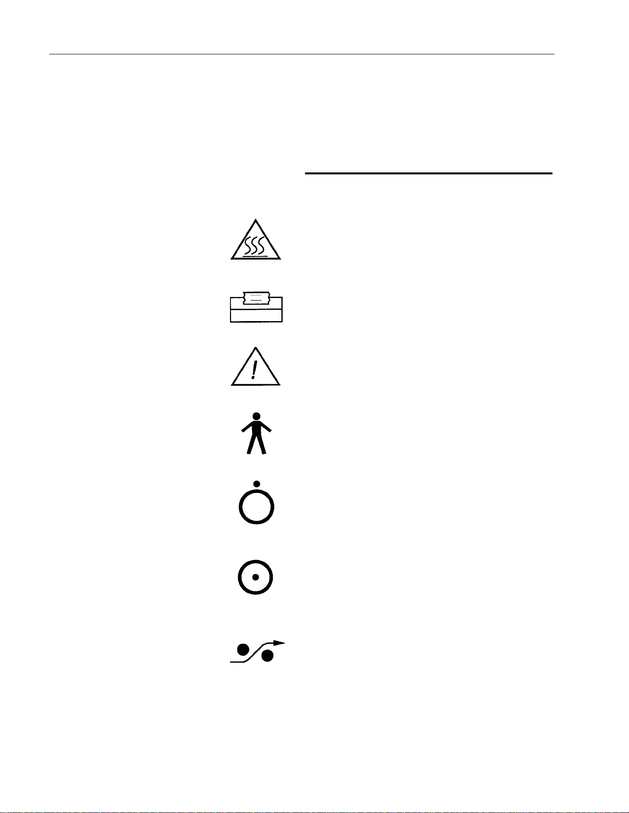
Description of Symbols on the Equipment ..................................................................................................8
General Description ..........................................................................................................................................10
Intended Use ..............................................................................................................................................10
General Usage............................................................................................................................................10
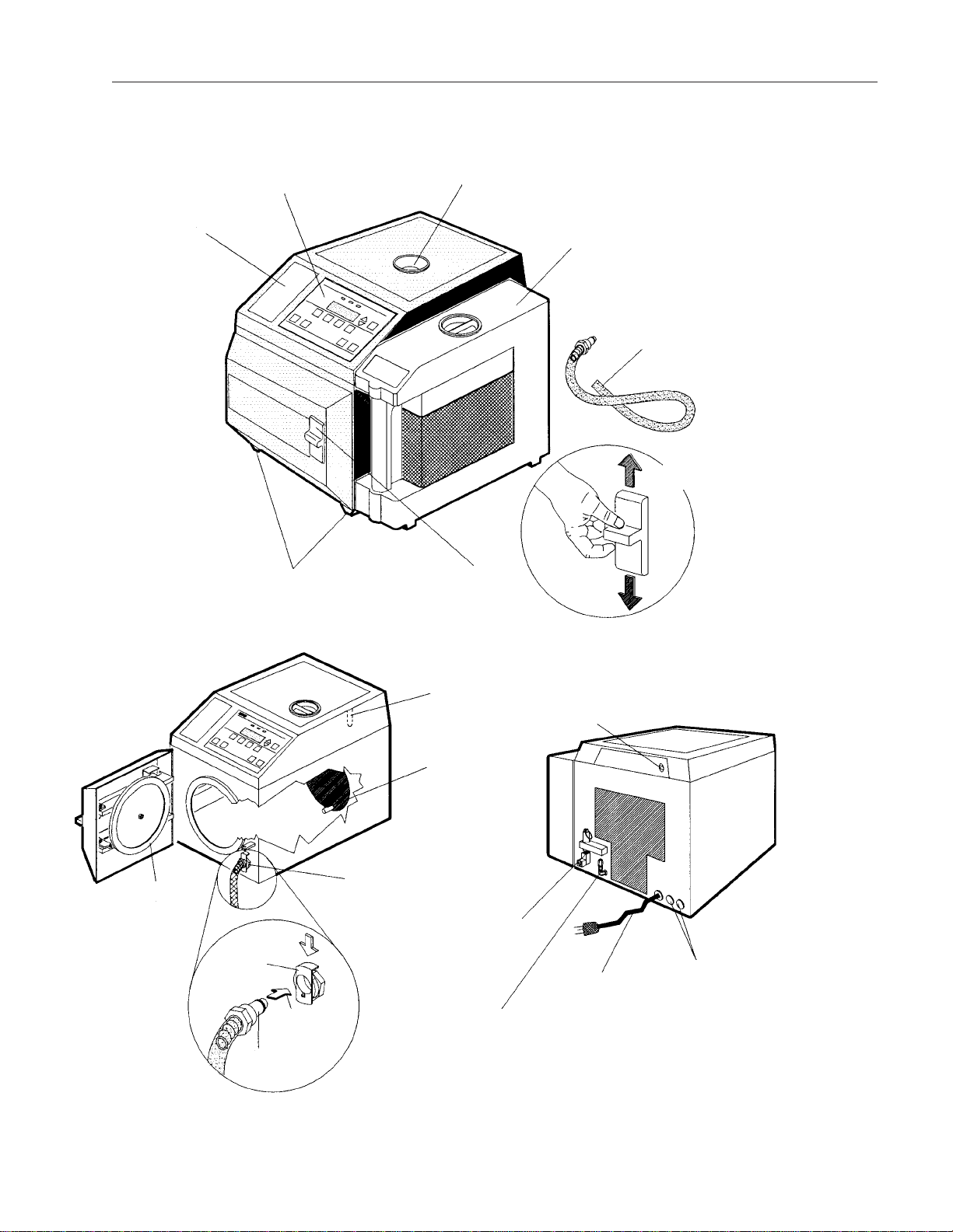
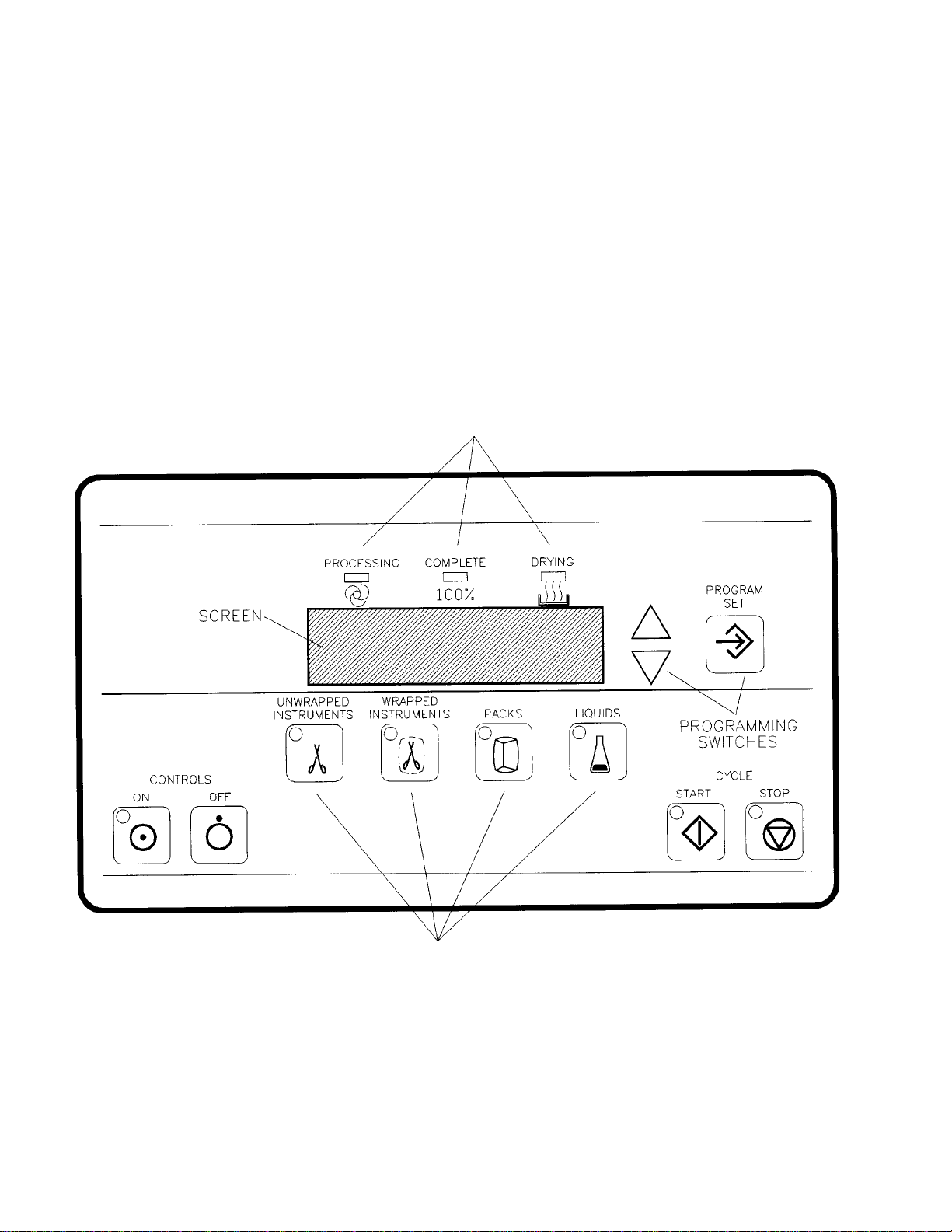
Operating Features ....................................................................................................................................10
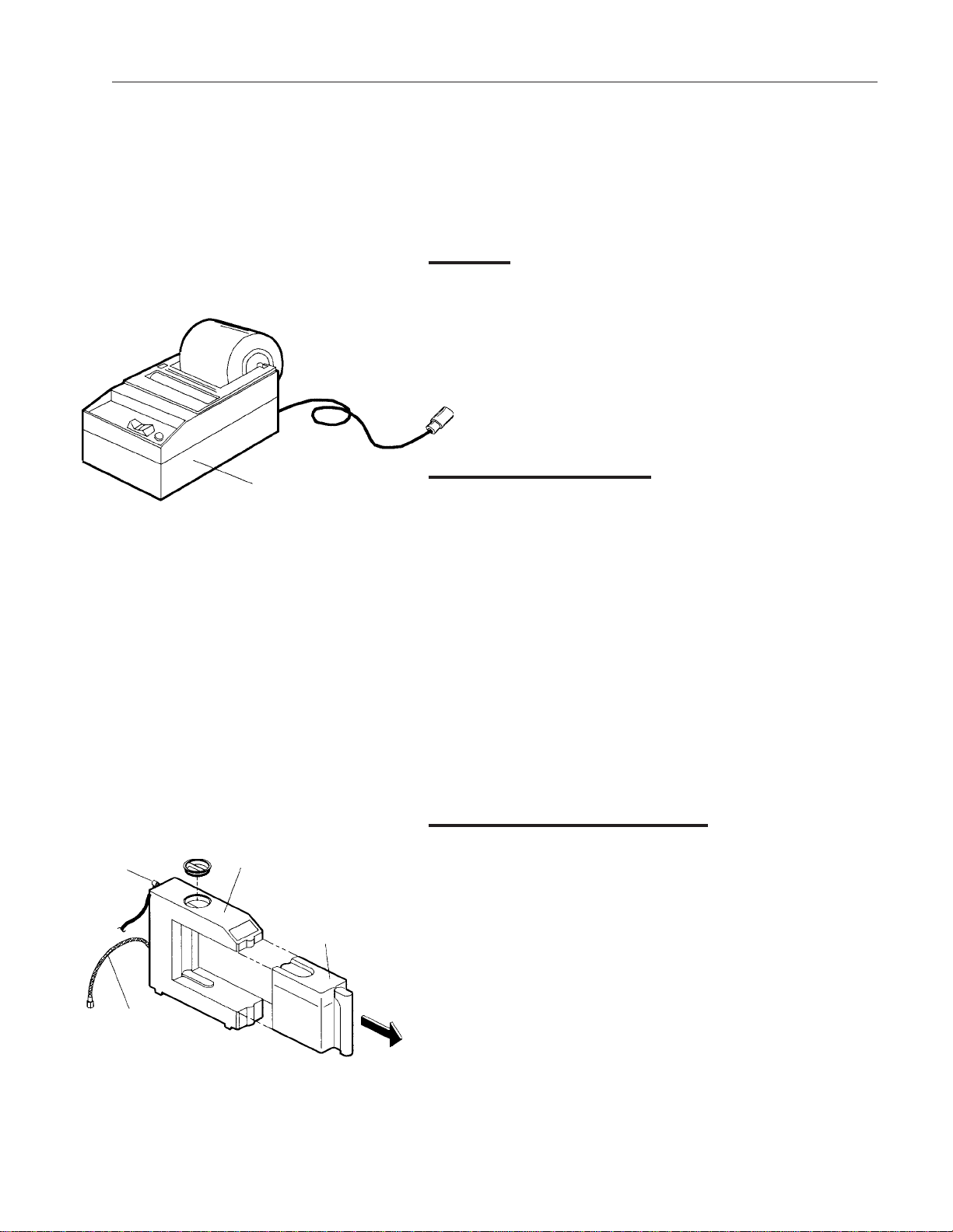
Printer ........................................................................................................................................................13
Non-Recirculating Water Accessory ..........................................................................................................13
Recommended Steam Sterilization Monitoring Program............................................................................13
Operation ..........................................................................................................................................................15
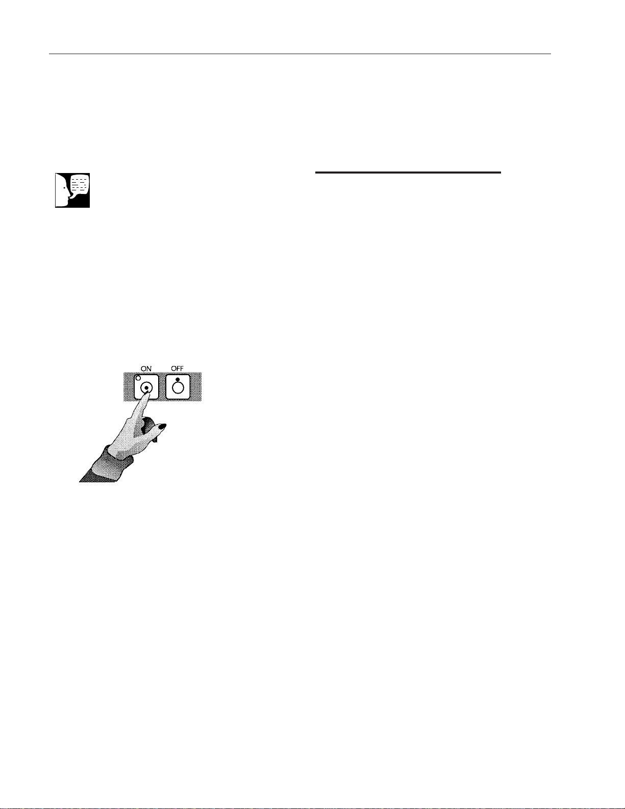
Power On/Controls On................................................................................................................................16
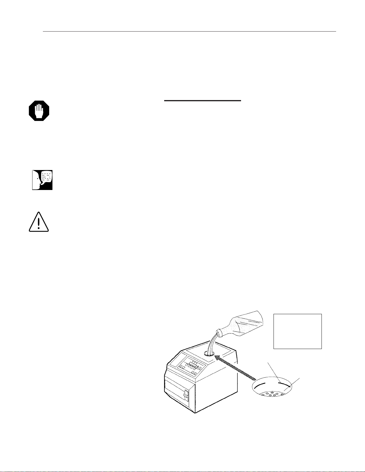
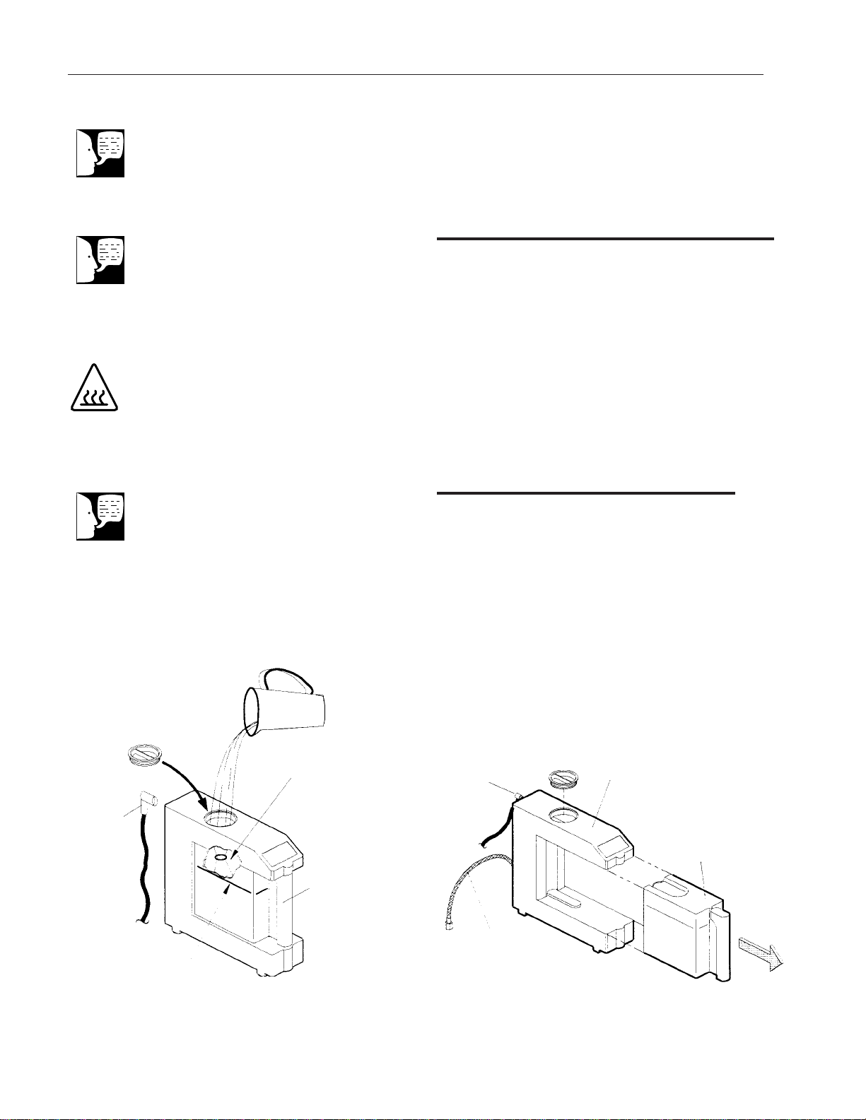
Filling Reservoir..........................................................................................................................................17
Filling Non-Recirculating Tank (Option)......................................................................................................18
Emptying Collection Bottle..........................................................................................................................18
Installing Overflow Tube (Optional) ............................................................................................................19
Load Chart..................................................................................................................................................20
Preparing Items for Sterilization ................................................................................................................21
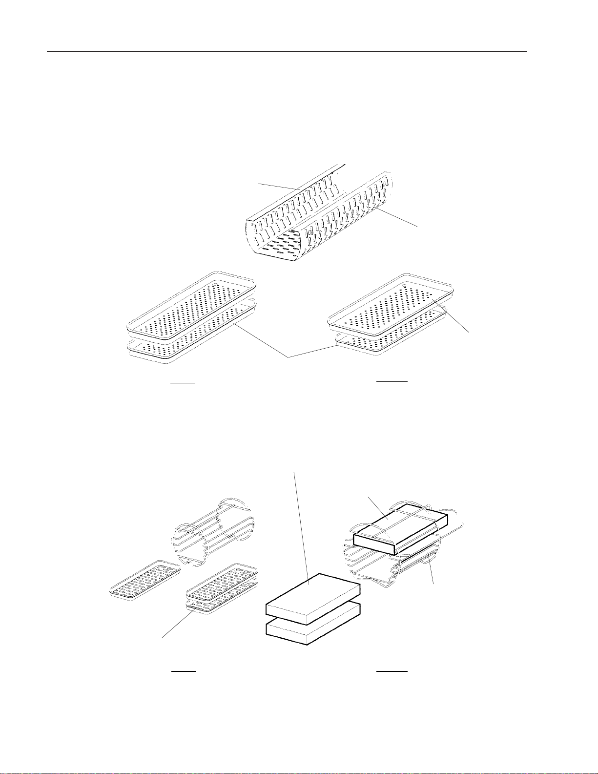
Loading ......................................................................................................................................................21
Selecting Cycle ..........................................................................................................................................22
Starting Cycle ............................................................................................................................................23
Drying Phase..............................................................................................................................................23
Open Door Drying ......................................................................................................................................24
Removing Load...........................................................................................................................................24
Additional Information........................................................................................................................................25
Cancel Cycle ..............................................................................................................................................25
Emergency Power Off ................................................................................................................................25
Power Failure During Cycle........................................................................................................................25
Diagnostic Messages........................................................................................................................................26
Troubleshooting ................................................................................................................................................27
Printer................................................................................................................................................................28
Installation ..................................................................................................................................................28
MC8......................................................................................................................................................28
MC10....................................................................................................................................................28
Operation....................................................................................................................................................28
Paper Roll Replacement ............................................................................................................................29
Ribbon Replacement..................................................................................................................................29
Printer Removal (MC10) ............................................................................................................................30
Operator Maintenance ......................................................................................................................................31
Daily............................................................................................................................................................31

3
Cleaning Door Gasket..........................................................................................................................31
Weekly........................................................................................................................................................31
Cleaning Chamber, Trays and Rack....................................................................................................31
Cleaning and Disinfecting Exterior Surfaces........................................................................................32
Every 25 Cycles..........................................................................................................................................32
Cleaning Reservoir ..............................................................................................................................32
Draining Reservoir................................................................................................................................32
Cleaning Reservoir Filter......................................................................................................................33
Cleaning Chamber Filter Screen..........................................................................................................33
When Required ..........................................................................................................................................34
Emptying Non-Recirculating Collection Bottle......................................................................................34
Cleaning Printer Recess (MC10) ........................................................................................................34
Replacing Door Gasket........................................................................................................................35
Every 6 Months ..........................................................................................................................................36
Cleaning Non-Recirculating Water Cooling Tank ................................................................................37
Recommended Spare Parts..............................................................................................................................38
Installation ........................................................................................................................................................39
Leveling Sterilizer Cabinet/Clearance/Electrical Connection......................................................................39
Non-Recirculating Water Accessory Installation ........................................................................................40
Setting the Clock/Calendar ........................................................................................................................41
Technical Data ..................................................................................................................................................46
Appendix ..........................................................................................................................................................47
Voltage Conversion (Dual Voltage Models Only) ......................................................................................47
115 VAC to 230 VAC ..................................................................................................................................48
Parts Required ....................................................................................................................................48
230 VAC to 115 VAC ..................................................................................................................................51
Parts Required ....................................................................................................................................51
Two-Year Limited Warranty ..............................................................................................................................56
TABLE OF CONTENTS

4
Introduction
As leaders in the field of sterilization, our goal is to engi-
neer and manufacture safe, efficient, quality sterilization
products. We are certain you will agree that this sterilizer
meets our goal.
Regardless of how well a piece of equipment is designed,
misuse, abuse, or neglect will deny its owner the safe, effi-
cient, quality service expected. Often, misuse, abuse or
neglect occurs unintentionally because the operator is
unaware of the proper operating and maintenance proce-
dures. This manual provides you with the information
required to properly operate and routinely maintain your
sterilizer. The information included in this manual applies to
all models unless noted for specific models.
We urge you to read this manual carefully before operating
the unit, and retain it for future reference.
Operation Overview
Hydroclave MC8 and MC10
Steam Sterilizer
The MC8 and MC10 sterilizer operates on the principle of
heated water converted to steam in a sealed pressure
chamber.
What happens when the controls are turned on?
•The chamber vent valve opens and the heater
turns on to warm up the chamber. The items to
be sterilized are placed on the trays and the
trays are placed inside the sterilizer chamber.
(Certain parameters such as positioning and
size of the load must be observed for proper op-
eration and satisfactory result.) Then, the door is
closed and latched, and the “START” button
pressed to start the cycle.

5
What happens when the cycle starts?
•The water fill valve opens and the proper
amount of water automatically flows from the
reservoir into the chamber.
•The water in the chamber begins to heat. As
the water turns to steam, the temperature and
pressure increase, forcing air from the cham-
ber.
•When the temperature in the chamber reach-
es the proper temperature (121 or 135°C) the
exposure timer begins. During this exposure
time, the temperature in the chamber is
automatically maintained at either 121 or
135°C, plus or minus about two degrees.
•At the completion of the exposure time a sole-
noid valve opens, allowing the steam and
water to vent back into the reservoir. The
steam reenters the reservoir through tubing
below the water level in the reservoir. The
water in the reservoir condenses the steam to
a liquid for reuse in the next cycle.
When the vent is complete an indicator light
on the control panel lights to alert the operator
that the cycle is complete.
Drying cycle
At the completion of the sterilization cycle, the drying
cycle automatically begins. This cycle continues until the
selected time has elapsed or the door is opened.
To restart a drying cycle that has been terminated by
opening the door; close the door (DO NOT LATCH) and
press the “START” button.
INTRODUCTION

6
Operator Maintenance
It is important to establish the maintenance schedule called
for in the Operator Maintenance section of this manual.
Daily
Before each days use: Check the water level in the reser-
voir. Refill with distilled or deionized water if needed. Clean
the door gasket and its mating surface.
Weekly
Clean the chamber, rack and trays once a week to prevent
a buildup of mineral deposits inside the chamber. Normal
tap water contains chemicals and minerals, chlorine being
the most common. Chlorine is especially corrosive to the
stainless steel chamber, trays and rack when water is
turned to steam during the sterilization process. It is impor-
tant to remove any mineral deposits regularly to ensure
peak operating efficiency.
Distilled or deionized water should always be used in the
MC8 and MC10 steam sterilizer. Even when distilled or
deionized water is used, some contaminants can collect in
the chamber, rack and trays.
Clean the reservoir, reservoir filter and chamber screen at
least every 25 cycles. A clogged filter and/or screen will
result in restricted water flow and prolong the time it takes
to fill the chamber.
Maintaining a clean reservoir, filter and chamber screen is
especially important. Foreign particles, such as bits of oil,
adhesives, amalgam, etc., can be picked up from items
being sterilized and returned to the reservoir, clogging the
filter and screen.
The daily and weekly maintenance should be performed as
outlined above to ensure long, trouble-free service. Failure
to routinely perform maintenance procedures could result
in processing delays or equipment down time and possible
equipment repairs.
Detailed maintenance procedures for those listed above
and also other “as required” items are shown in the
Operator Maintenance section of this manual.
INTRODUCTION

7
Safety Information
The special safety information instructions that follow
appear within the manual. Read them carefully before
operating the unit and follow instructions.
Declaration of Conformity
Barnstead International hereby declares under its sole
responsibility that this product conforms with the technical
requirements of the following standards (applies to units
with CE mark on unit spec label only):
EMC: EN 61000-3-2 Limits for Harmonic Current
Emissions
EN 61000-3-3 Limits for Volatge Fluctuations and
Flicker
EN 61326-1 Electrical Equipment for
Measurement, Control and
Laboratory use;
Part I: General Requirements
Safety:EN 60601 Medical Electrical
IEC 601-1 Equipment; Part 1:General
Requirements for Safety
per the provisions of the Electromagnetic Compatibility
Directive 89/336/EEC, as amended by 92/31/EEC, and per
the provisions of the Low Voltage Directive 73/23/EEC, as
amended by 93/68/EEC.
The authorized representative located within the European
Community is:
Electrothermal Engineering, Ltd.
419 Sutton Road
Southend On Sea
Essex SS2 5PH
United Kingdom
Copies of the Declaration of Conformity are available upon
request.
This equipment has been tested and
found to comply with the limits for a
Class A digital device, pursuant to Part
15 of the FCC rules. These limits are
designed to provide reasonable pro-
tection against harmful interference
when the equipment is operated in a
commercial environment. This equip-
ment generates, uses and can rediate
radiofrequency energy and, if not in-
stalled and used in accordance with
the instruction manual, may cause
harmful interference to radio communi-
cations. Operation of this equipment
in a residential area is likely to cause
harmful interference in which case the
user will be required to correct the
interference at his own expense.
NOTE
Warning
Warnings alert you to a possibility of per-
sonal injury.
Caution
Cautions alert you to a possibility of
damage to the equipment.
Note
Notes alert you to pertinent facts and
conditions.
Hot Surface
Hot surfaces alert you to a possibility of
personal injury if you come in contact
with a surface during use or for a period
of time after use.
Alert Signals

8
SAFETY INFORMATION
Description of Symbols on the
Equipment
Hot Surface
Printer Receptacle
Attention: Consult Accompanying Documents
(Refer to Warning and Caution notes in this
manual.)
Type B Equipment, Class I
(Refer to IEC Standard 601-1.)
OFF (Only for a part of equipment.)*
ON (Only for a part of equipment.)*
Paper Feed
* Does not disconnect equipment from mains voltage (AC
power)

9
Hydroclave MC8/MC10 Sterilizer Overview
Control Panel
MC10
Printer
(Optional)
Reservoir
Fill Funnel
Non-Recirculating
Water Accessory
(Optional)
Drain
Tube
Open
Lock
Printer
Receptacle
(MC8)
Fuse(s)
Power Cord
Discharge Port
Non-Recirculating
Pressure
Relief
Valve
Water Fill
Port &
Chamber
Filter Screen
Reservoir
Drain Valve
Door
Gasket
Leveling
Feet
Push To
Release
Release
Tab
Click In
To Drain
Drain
Fitting
Reservoir
Filter
Screen
Locking
Handle

10
Intended Use
The Hydroclave MC8 and MC10 Sterilizers have been
designed for use in medical and dental offices, hospitals, clin-
ics, laboratories and other facilities where a variety of materials
require processing.
This steam sterilizer can be used for wrapped or unwrapped
instruments, linen packs, and liquids. Glassware may be
processed using the liquids cycle.
General Usage
Do not use this product for anything other than its intended
use.
Operating Features
•Four preset sterilizing cycles—unwrapped instru-
ments, wrapped instruments, packs and liquids. Ex-
posure and drying times are adjustable.
•Automatic closed door drying and optional open
door drying (except for liquid cycle). Drying times
are adjustable.
•Cycle runs automatically when START switch is
pressed.
•Optional printer records temperature and pressure
during cycle.
•Chamber temperature may be displayed in °C or °F.
•Chamber temperature is displayed continuously
throughout cycle (excluding dry phase) and may be
displayed in psi, kPa or bars.
•Messages may be displayed in English, French,
Spanish or German.
•Clock format may be 12-hour or 24-hour.
•Non-recirculating discharge of steam is available as
an option. This option may be installed in the field
by a service technician or purchased and installed
by the owner/operator.
General Description
Warning
Volatile Reaction: Do not use this
sterilizer for processing volatile sub-
stances or for any purpose other
than its intended design. Failure to
heed this warning could cause per-
sonal injury to personnel or damage
to equipment.

11
GENERAL DESCRIPTION
Figure 1
Control Panel
Harvey
Hydroclave MC8
Cycle Phase Indicators
Cycle Select Switches

12
GENERAL DESCRIPTION
Figure 3
Optional Accessories
Figure 2
Standard Accessories
MC8 MC10
Support
Flange
Tray Rack
(MC8 - Part No. 265002)
(MC10 - Part No. 2-513025)
Large Tray
(Part No. 2-67811)
Small Tray
(Part No. 265001)
Wrapped
Cassette
IMS®Cassette
(Not Sold By B/T)
IMS®
Cassette Rack (Holds
MC10 - Part No. 260761)
Four
Tray Rack
(MC8 - Part No. 265024)
Trays
MC8 MC10

13
Printer
The MC8 printer is a separate unit connected to the steril-
izer by a plug-in cable and a separate power supply. The
optional MC10 printer is an integral part of the Control
Panel.
Non-Recirculating
Water Accessory
Standard MC8 and MC10 sterilizers discharge steam back
into the reservoir. For sterilizers with the non-recirculating
system, the distilled water is used to make steam in the
chamber for one cycle only. Used water (steam) is ex-
hausted into the cooling tank which then overflows into the
collection bottle. The collection bottle is then emptied when
full.
An optional overflow tube is provided for connection to the
back of the cooling tank. This feature allows the excess
water to drain directly into a sink or drain (if available),
eliminating the need to periodically empty the collection
bottle.
Recommended Steam
Sterilization Monitoring Program
All functions of the sterilizer should be monitored to provide
maximum sterilization assurance.
The Joint Commission on Accreditation of Hospitals and
the American Dental Association recommends that biologi-
cal indicators be used at least weekly to check the effec-
tiveness of steam sterilizers to sterilize; i.e., to kill test
organisms of a known high resistance. (Bacillus stearother-
mophilus is the recommended test organism for monitoring
steam sterilization.)
GENERAL DESCRIPTION
Figure 5
Non-Recirculating Water Accessory
Waste Water
Cooling
Tank
Collection
Bottle
From
Sterilizer
Optional
Overflow
Drain
Figure 4
MC8 Printer
MC8
Printer

14
We recommend the use of process indicators such as
the B|T Check Indicator within each package of each
cycle. For additional assurance that minimum sterilizing
conditions have been achieved, a biological indicator
such as B|T Sure should be used at least once a week.
GENERAL DESCRIPTION
Description Part No.
Chemitest Self-Sealing Bags
Tray Size: 5” x “ x 55” (150 per box) 230300001
Instrument Size: 2.5” x 1.5” x 10.5” (250 per box) 230301001
Chemitest See-Thru Indicator Pouches
Tray Size: 5” x 15.5” (150 per box) 230302001
Biological Indicators
B|T Sure Biological Indicator (Box of 5 Indicator vials) Spore Population 105AY759X1
B|T Sure Biological Indicator (Box of 100 Indicator vials) Spore Population 105AY759X3
B|T Sure Biological Indicator (Box of 100 Indicator vials) Spore Population 106AY759X8
Process Indicators
Chemical Indicator Strips (Box of 250) Steam Sterilizers Only. AY759X2
Chemitest Indicator Tape—Closure system for packs, bags or other containers 260577
Roll is 1.5” (3.8 cm) x 360” L (91.4 mm)
Chemitest Indicator Strips, (Box of 250) Chemiclave Sterilizers Only. 230305001
Chemitest Indicator Tabs, Roll of 250, Self-adhering tabs, 1.5” (3.8 cm) sq. 230306001
Instrument Packaging for Clean Process and Temperature Verification
Chemi-Test See-thru, Self-Sealing Pouches (Box of 200) 2.25” x 5” ZSX152
Chemi-Test See-thru, Self-Sealing Pouches (Box of 200) 2.75” x 10” ZSX153
Chemi-Test All Paper, Self-Sealing Pouches (Box of 250) 2.5” x 10.5” 230301001
Chemi-Test See-thru, Self-Sealing Pouches (Box of 200) 3.5” x 10” ZSX155
Chemi-Test See-thru, Self-Sealing Pouches (Box of 200) 5.25” x 11” ZSX156
Chemi-Test All Paper, Self-Sealing Pouches (Box of 150) 5” x 15” 230300001
Chemi-Test See-thru, Non-self-Sealing Pouches (Box of 150) 5” x 15” 230302001

15
1. Press Controls ON.
2. Fill Reservoir.
3. Load Chamber.
4. Lock Door.
5. Select Cycle.
6. Press START.
7. Open Door to Dry.*
8. Remove Load.
* Optional—Drying phase, if selected, will start automati-
cally without opening the door. Opening the door, however,
may improve drying efficiency.
Operation
Operation
Warning
Patient Safety Zone: Do not oper-
ate this sterilizer within 6 ft. (2 m) of
patient treatment point.

16
Power On/Controls On
1. When the sterilizer is plugged in and the con-
trols are off, the time and date will be dis-
played.
2. Press Controls ON switch to turn on the con-
trol panel. The cycle temperature, exposure
time and drying time will be displayed and the
Standby Mode will begin. During the Standby
Mode, the heater turns on to warm the cham-
ber to approximately 38°C. The heater then
cycles ON and OFF to maintain the warm
temperature.
3. Turn ON the optional printer (see Printer sec-
tion).
OPERATION
Power On/Controls On
Note
If time and date are incorrect, reset
the clock/calendar.

17
Filling Reservoir
Add distilled or low quality deionized water (minimum 0.5
megohm/cm, maximum 1.5 megohm/cm) to the reservoir
up to the fill line. The MC8 reservoir holds approximately 3
liters; the MC10 reservoir, 4 liters. Do not overfill.
OPERATION
Figure 7
Filling Reservoir
Fill Funnel
Use Distilled
or Low Quality
Deionized Water
Only
Fill To Mark
Refill
Fill
Caution
Use only distilled or low quality
deionized water (minimum 0.5
megohm/cm, maximum 1.5
megohm/cm). Normal tap water
contains minerals that will corrode
sterilizer parts.
Warning
Burn Hazard: Do not add water to
the reservoir while sterilization cycle
is in progress. Steam vented into
reservoir at end of cycle could result
in possible burns.
The water in the reservoir could be
HOT if multiple cycles have been
run in succession.
Reservoir lid must be in place when
sterilizer is in use.
Note
Be sure reservoir drain valve is
closed before filling the reservoir.

18
Filling Non-Recirculating Tank
(Option)
1. Remove the cap from the cooling tank.
2. Fill the cooling tank with distilled or deionized
water until the water begins to flow from the
cooling tank into the collection bottle (or into
the drain if the overflow tube is installed).
3. Replace the cap.
Emptying Collection Bottle
1. Empty the collection bottle when the water in
the bottle reaches the FULL mark.
2. Slide the bottle away from the cooling tank to
remove.
3. Pour the contents down the drain.
OPERATION
Figure 9
Emptying Collection Bottle
Optional
Overflow
Drain
Waste Water
Cooling
Tank
Collection
Bottle
From
Sterilizer
Figure 8
Non-Recirculating Water Accessory
Fill With Distilled or
Low Quality Deionized
Water Until It Overflows
Into the Collection Bottle
(Approx. 3 Gal.)
Collection
Bottle
Remove Cap
Optional
Overflow
Drain
Full Mark
Note
The cooling tank must be connected
to the sterilizer before filling the tank
with water.
Note
Do not operate sterilizer unless the
cooling tank is filled with distilled or
deionized water and attached to the
sterilizer.
Note
It is important to periodically check
the water level in the collection bot-
tle. Failure to empty the bottle when
full will result in water overflowing
onto surrounding surfaces.
Hot Surface
Burn Hazard: Do not empty the col-
lection bottle when the sterilizer is in
operation.

19
Installing Overflow Tube
(Optional)
If the sterilizer is located within 5 ft. (1.5 m) of a sink or
drain, the overflow tube may be used. The collection bottle
will not require emptying while the automatic overflow is
used.
1. Push the overflow tube (supplied) into the upper
quick connect on the back of the cooling tank.
2. Push the tube connector in until it “clicks.”
3. Place the end of the overflow tube in a sink or
drain(atmospheric drain).
OPERATION
Note
The sink or drain must be below the
level of the cooling tank for the
water drain.
Warning
Volatile Reaction: Do not use this
equipment for processing volatile
substances or for any purpose other
than its intended design. Failure to
observe this warning could cause
personal injury or damage to equip-
ment.
Warning
Burn Hazard: To prevent the possi-
bility of injury from liquids boiling
over and/or containers exploding,
use only self-venting automatic seal-
ing stoppers recommended by man-
ufacturers when processing all con-
tainer liquids or media.
Caution
Be sure items can withstand cycle tem-
perature before placing them in steriliz-
er. If in doubt, refer to device manufac-
turer’s instructions.
Note
Be sure to select the correct cycle for
the type of load. Sterilization cannot
be assured if maximum load size and
density are exceeded. Total specified
weight should not be exceeded for
any sterilizer cycle.
Note
Use the LIQUIDS cycle to process
glassware.

20
OPERATION
elcyC8CM01CM
depparwnU stnemurtsnI )gk5.4(.sbl01)gk4.5(.sbl21
depparW stnemurtsnI
depparw-elbuod)gk7.2(.sbl6 .stnemurtsni -elbuod)gk5.4(.sbl01 .stnemurtsnidepparw
,settessac*SMIlatemllamseerhT .zo21,depparw-elgnis,"7x"5 .hcae)g043(
,settessac*SMIeerhT .sbl5.1,depparw-elgnis .hcae)g086(
ytnewtrosehcuop"01x"6thgiE degnihowt,sehcuop"5x"3 .hcuoprepstnemurtsni
rosehcuop"01x"6neetruoF ,sehcuop"5x"3thgie-ytnewt repstnemurtsnidegnihowt .hcuop
skcaP.kcap95#.cepsADAenO.skcap95#.cepsADAowT
sdiuqiL.lluf%57,srekaeblm052eerhT.lluf%57,sksalfretilenoeerhT
* IMS is a trademark of Hu-Friedy Mfg. Co., Inc.
Load Chart
Other manuals for Harvey Hydroclave MC8
1
This manual suits for next models
1
Table of contents
Other Barnstead International Laboratory Equipment manuals

Barnstead International
Barnstead International DIamond 1265 Series User manual

Barnstead International
Barnstead International Cimarec series User manual

Barnstead International
Barnstead International Harvey Hydroclave MC8 User manual

Barnstead International
Barnstead International General Purpose Aquabath 18002 User manual

Barnstead International
Barnstead International 379 Series User manual

Barnstead International
Barnstead International 1085 Series User manual