Bartec ER 100ims User manual

Central-Interlocking Leakage
Safety Device ER 100ims
type
Operation Manual
no. BP/IO/21/16
18th November 2020
Edition 5.2.1
BARTEC Polska Sp. z o.o.
43-100 Tychy
ul. Graniczna 26A
tel: +48 32 326 44 00
fax: +48 32 326 44 03
email: [email protected]

Index No.: BP/IO/21/16
Date: 18th November 2020
Edition: 5.2.1

Contents
1 Introduction ......................................... 5
1.1 Copyright . . . . . . . . . . . . . . . . . . . . . . . . . . . . . . . . . . . . . . . 5
1.2 Warranty terms and conditions . . . . . . . . . . . . . . . . . . . . . . . . . . . . 5
2 Safety of operation . . . . . . . . . . . . . . . . . . . . . . . . . . . . . . . . . . . . . 5
3 Identification of hazards . . . . . . . . . . . . . . . . . . . . . . . . . . . . . . . . . . 5
3.1 Hazards........................................ 5
3.2 Application restrictions . . . . . . . . . . . . . . . . . . . . . . . . . . . . . . . . 6
3.3 Directions for safe use . . . . . . . . . . . . . . . . . . . . . . . . . . . . . . . . 6
4 Intendeduse ........................................ 7
5 Operating conditions . . . . . . . . . . . . . . . . . . . . . . . . . . . . . . . . . . . . 8
6 Technical parameters . . . . . . . . . . . . . . . . . . . . . . . . . . . . . . . . . . . . 9
7 Identification . . . . . . . . . . . . . . . . . . . . . . . . . . . . . . . . . . . . . . . . . 10
7.1 Type.......................................... 10
7.2 Ex-proof protection rating identification . . . . . . . . . . . . . . . . . . . . . . . 10
7.3 Marking ........................................ 10
8 Construction and principle of operation . . . . . . . . . . . . . . . . . . . . . . . . . . 11
8.1 Mechanical structure . . . . . . . . . . . . . . . . . . . . . . . . . . . . . . . . . 11
8.2 Electrical equipment . . . . . . . . . . . . . . . . . . . . . . . . . . . . . . . . . 11
8.2.1 Scheme of connections . . . . . . . . . . . . . . . . . . . . . . . . . . . . 11
8.2.2 Principle of operation . . . . . . . . . . . . . . . . . . . . . . . . . . . . . 12
8.2.3 Additional equipment . . . . . . . . . . . . . . . . . . . . . . . . . . . . . 12
9 Resistance indicator ER 100ws . . . . . . . . . . . . . . . . . . . . . . . . . . . . . . 12
10 Intrinsically-safe line specifications . . . . . . . . . . . . . . . . . . . . . . . . . . . . 13
10.1 Parameters of ER 100ims . . . . . . . . . . . . . . . . . . . . . . . . . . . . . . 13
10.2 Parameters of ER 100ws . . . . . . . . . . . . . . . . . . . . . . . . . . . . . . . 14
11 Service and operation . . . . . . . . . . . . . . . . . . . . . . . . . . . . . . . . . . . 14
11.1 Installation . . . . . . . . . . . . . . . . . . . . . . . . . . . . . . . . . . . . . . . 14
11.2 Electric shock protection . . . . . . . . . . . . . . . . . . . . . . . . . . . . . . . 14
11.3 Storage and transport conditions . . . . . . . . . . . . . . . . . . . . . . . . . . 14
11.4 Inspections and maintenance principles . . . . . . . . . . . . . . . . . . . . . . . 15
11.5Repairs ........................................ 15
11.6 Disposal . . . . . . . . . . . . . . . . . . . . . . . . . . . . . . . . . . . . . . . . 15
11.7 PN-G-42040 setting resistance . . . . . . . . . . . . . . . . . . . . . . . . . . . 15
11.8 Central/interlocking trip settings . . . . . . . . . . . . . . . . . . . . . . . . . . . 15
11.9 Setting of indication of ER 100ws display . . . . . . . . . . . . . . . . . . . . . . 16
12 Reference standards . . . . . . . . . . . . . . . . . . . . . . . . . . . . . . . . . . . . 19
13Endnotes.......................................... 19
14 Orders and service . . . . . . . . . . . . . . . . . . . . . . . . . . . . . . . . . . . . . 20

List of Figures
Figure 1 Protection ER 100ims . . . . . . . . . . . . . . . . . . . . . . . . . . . . . 11
Figure 2 Implementation of the warning signal . . . . . . . . . . . . . . . . . . . . . 12
Figure 3 Resistance indicator ER 100ws . . . . . . . . . . . . . . . . . . . . . . . . 13
Figure 4 Wiring connection layout of the earth leakage central trip . . . . . . . . . . 17
Figure 5 Wiring connection layout of an earth leakage interlocking trip . . . . . . . . 18
List of Tables
Table 1 Change of leads . . . . . . . . . . . . . . . . . . . . . . . . . . . . . . . . 8
Table 2 Enclosure technical specifications . . . . . . . . . . . . . . . . . . . . . . . 8
Table 3 Operating conditions . . . . . . . . . . . . . . . . . . . . . . . . . . . . . . 8
Table 4 Technical parameters . . . . . . . . . . . . . . . . . . . . . . . . . . . . . . 9
Table 5 Connection of resistance indicator ER 100ws to relay ER 100ims . . . . . . 13
Table 6 PN-G-42040 setting resistance of the earth leakage trip . . . . . . . . . . . 16
Table 7 Reference standards . . . . . . . . . . . . . . . . . . . . . . . . . . . . . . 19

Operation Manual no. BP/IO/21/16 ed. 5.2.1
1 Introduction
The Operation and Safety Manual, no. BP/IO/21/16 is intended to provide the users of the
ER 100ims multifunctional relay (also referred to as „the product”) with the product design, oper-
ating principle and procedures of safe and correct operation.
1.1 Copyright
BARTEC Polska Sp. z o.o. reserves all intellectual property rights to the ER 100ims multi-
functional relay.
1.2 Warranty terms and conditions
The warranty terms and conditions are specified in BARTEC’s „General Terms and Conditions
of Sale and Delivery”.
All warranty claims and/or claims for material or personal damage will be rejected whenever
caused by:
• non-intended use of the product,
• improper transport, handling, storage, installation, wiring, commissioning, servicing, main-
tenance, repairs, removal and/or recycling,
• non-compliance with this Manual,
• unauthorized modifications in the connection layout of the product,
• improper inspection of wearing parts of the product,
• emergency caused by contact with foreign bodies or other causes.
2 Safety of operation
The product shall only be installed by qualified personnel trained in operation of Ex-rated
electrical equipment.
During operation, observe the requirements for maintaining the efficiency of the device, in
accordance with the documentation.
The protection features shall be calibrated according to their operating manuals approved for
use by the mine operations manager or another competent authority.
All repairs and maintenance of the ER 100ims shall be attempted with the live supply voltage
isolated and locked out from the equipment unit it is integrated with.
3 Identification of hazards
3.1 Hazards
The Operation Manual specifies sufficiently the correct maintenance of the product. However,
the personnel attempting maintenance shall hold valid electrical licenses.
WARNING: Read this Operation Manual prior repairing or maintaining this product.
ER 100ims Page 5

Operation Manual no. BP/IO/21/16 ed. 5.2.1
WARNING: Do not attempt to repair the product if you do not have the required qualific-
ations. Only BARTEC is authorized for the repairs. Improper or careless repair can lead
to serious accidents or death.
WARNING: Modification of the product or use of any spare part which does not comply
with BARTEC’s engineering conditions may result in severe injury and/or death hazards
and will result in loss of warranty rights and product approval.
3.2 Application restrictions
The field installation of the product shall follow the Operation Manual.
RESTRICTION: Do not attempt any makeshift installation of the product.
RESTRICTION: The use of the ER 100ims central-interlocking device is only possible in
conjunction with ED 100 or ED 100i chokes (or suitably rated wire resistors).
RESTRICTION: The installation shall be done with the required separation distances
from the external terminals of the product in compliance with EN 60079-11 Section 6.2.1
RESTRICTION: The ambient temperature limits are: −20°C ≤Ta ≤+70°C.
3.3 Directions for safe use
1. Prior to operating the product, read and understand this Operation and Safety Manual.
Refer also to the documentation of the system in which the product is operated.
2. Compliance with the Operation Manual and the guidelines and parameters listed in the
system documentation will guarantee reliable operation of the product. The user shall strictly
comply with the rules of operation. Non-compliance may result in loss of warranty right,
damage of the product or create operating hazards.
3. The management in the product user’s organisation is required to provide adequate training
for prospective operators of the product.
4. The only operators authorized to work with the product shall be properly qualified.
5. Follow all applicable health and safety regulations and this Manual.
6. Do not modify the product or use it with any spare parts which do not meet BARTEC’s
specifications for genuine spare parts. Unauthorized attempts at repairs of the product
may result in severe hazards to the operators and other personnel, and void the warranty,
certification and/or approvals.
7. All test instrument used for servicing of electrical equipment components shall comply with
applicable regulations.
8. Troubleshoot and maintain the product in witness of a trained assistant capable of isolating
the main power supply and providing first aid as necessary.
9. Any attempt at starting failed electrical equipment may result in hazards to operator’s health
or life and failure to other equipment.
Page 6 ER 100ims

Operation Manual no. BP/IO/21/16 ed. 5.2.1
4 Intended use
Annex 3 to the OBAC 06 ATEX 059U certificate introduces a number of changes in the struc-
ture of ER 100ims leakage protection, which are designed to adapt to the current standards and
to change the method for processing the measurement signal. In addition, two variants (with and
without reset button) were replaced with one universal design. The manual reset function is ac-
tivated by means of the switch on the front of the unit. In this way, backward compatibility has
been maintained. The new version replaces previous versions of the device.
The ER 100ims type safety device is used to control the insulation state in insulated low
voltage electricity networks. Depending on the method of safety device connection to the con-
trolled network it may fulfil the following functions:
• Central leakage protection of three-phase alternating voltage network. In this case it is
preferable to connect the device through three chokes which ED 100i are connected with
one end to three phases of the network and with second end are connected in one point
creating „artificial zero” layout to which the measuring relay ER 100ims of the protection is
connected or directly to the N terminal of the transformer. It is possible to connect by one
choke connected at one end to the neutral point of the transformer (alternative connection).
• Central leakage safety device of a single phase voltage network. In this case it is preferable
to connect the device through two ED 100i chokes are connected by one end to phase
conductors of the network and by the other end are connected in one point, to which the
measuring relay ER 100ims of the safety device is connected or directly to the N terminal of
the transformer. It is possible to connect by one choke connected at one end to the neutral
point of the transformer (alternative connection).
• Interlocking leakage safety device in three- and single phase networks.
The measuring circuit of the measuring relay ER 100ims can work with the network controlled
only through chokes ED 100i or ED 100.
The following functions are fulfilled in the applications specified:
• Signalling and/or disconnecting at deterioration of the insulation state below the preset ref-
erence value, at the same time a controlled dropout time relay is released, which by its
contacts signals the operation and/or disconnects a circuit breaker or relay.
• Measurement and indication of the insulation state, where the spark-proof analogue input
may be connected with a spark-proof voltage indicator (0÷10 V) rescaled to the insulation
resistance reading, e.g. ER 100ws and/or spark-proof voltage transducer to another ana-
logue signal to transmit this information to other control and monitoring systems.
A non-spark-proof circuit consists of relay contacts and coil and also of safety device power
supply. The analogue output may be connected to spark-proof circuits of the ia protection level
(e.g. ER 100ws or spark-proof signal separator), while its measuring circuit, through the system
of ER 100i chokes, sends a spark-proof signal of ia protection level to the controlled network.
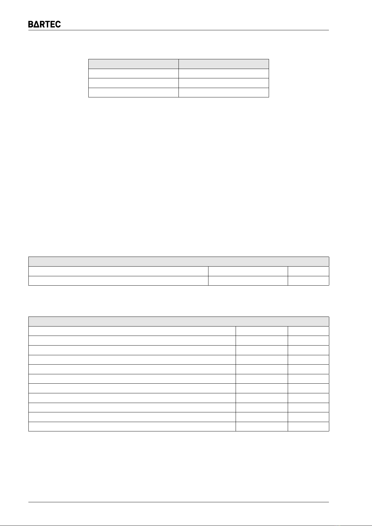
WARNING: For connecting the ER 100ims in place of the previous version without reset
button, terminals connection of the device remains unchanged. In the case of installing
the ER 100ims in place of the previous version with reset button, change the connections
of the terminals (tab. 1).
ER 100ims Page 7

Operation Manual no. BP/IO/21/16 ed. 5.2.1
Table 1: Change of leads
Terminal ER 100im Terminal ER 100ims
21 20
22 21
23 22
RESTRICTION: The device is designed to work in networks of alternating current with
a nominal frequency of 50Hz. Due to its structure of working principle (measuring DC),
the device CANNOT BE installed within the networks with receivers transforming AC
power into DC power directly, without additional separating transformer. It relates mainly
to rectifiers and receivers with DC intermediary circuits of inverters supplied directly from
the protected network.
5 Operating conditions
For explosion hazard zones, the product is intended for operation if confined to an external
flameproof enclosure marked with the Ex d making or in non-hazardous areas if confined to an
enclosure with a minimum ingress protection rating IP54 (IP65).
Table 2: Enclosure technical specifications
Enclosure technical specifications
Oveall dimensions (width x height x depth) 112 ×100 ×35 mm
Weight 0,27 kg
Table 3: Operating conditions
Operating conditions
Maximum installation elevation ≤1000 m
Ambient temperature −20…+70 °C
Relative humidity (non-condensing) at 40°C ≤95 %
Transport temperature −20…+60 °C
Transport relative humidity ≤95 %
Mechanical exposure – frequency 10…55 Hz
Mechanical exposure – amplitude 0,35 mm
Vibration resistance (10…55Hz) 5 g
Impact strength 7 Nm
Operating orientation any —
Duty continuous —
Page 8 ER 100ims

Operation Manual no. BP/IO/21/16 ed. 5.2.1
6 Technical parameters
Table 4: Technical parameters
Technical parameters
DC/AC input power 1 W/VA 50Hz
Rated DC/AC supply voltage 24/42 V
Permitted AC supply voltage 17…53 V
Permitted DC supply voltage 19…75 V
Contacts 2 change-over contacts
Relay mechanical strength 3 • 107
Rated load 250VAC 5A
120VAC 3A
240VAC 1,5A
30VDC 4A
120VDC 0,22A
250VDC 0,1A
AC1
AC15
AC15
DC1
DC13
DC13
Open contact insulation strength 1000 V AC/DC
Coil-to-contact insulation strength 5 kV
Ingress protection rating IP20
Measuring voltage 18 ± 5% V
Rated network voltage ≤1140 V AC
Rated frequency of the protected network 50 Hz
Settings range 2…120 kΩ
Leakage stage tripping time (preferred connection layout, see Fig. 4a-
4d, with incremental change of leakage resistance from infinity to 1kΩ
ref. PN-G-42040)
≤100 ms
Leakage stage tripping time (preferred connection layout, see Fig. 4e-
4h, ref. PN-EN 50628)
≤200 ms
Additional time delay 0…1,5 s
Return value min. 30% above the response
threshold
Measuring output (analogue spark-proof)10…10 V
1at Rimin = 100kΩ
ER 100ims Page 9

Operation Manual no. BP/IO/21/16 ed. 5.2.1
7 Identification
7.1 Type
ER 100*
(protection and resistance indicator):
im – device according to Annex 2a,b
m– non ATEX version of ER 100im typea,b,c
ims – device according to Annex 3d
ms – non ATEX version of ER 100ims typec,d
w– resistance indicator according to Annex 2b
ws – resistance indicator according to Annex 3
ED 100*
(choke):
i– choke for the measuring circuit for
i.2p – double choke for the measuring circuit for protectione
i.3p – triple choke for the measuring circuit for protectione
aThe version with reset button is marked by adding „R” to the serial number
b3) For this version, the instruction manual no. BP/IO/04/05 applies
cHowever, the measurement output energy is limited and will not cause ignition
d5) Additional designation „/J” means the version with external connection of the measuring stage (terminal
no. 3) with the executive stage (terminal no. 9)
e6) For central leakage protection, it can be used for networks with nominal voltage up to 500V
WARNING: The ER 100im, ER 100w can be replaced by ER 100ims, ER 100ws. It is not
permissible to connect devices made according to the Annex no. 3 with devices made
according to the earlier version.
7.2 Ex-proof protection rating identification
I (M1) [Ex ia Ma] I – ER 100ims
I M1 Ex ia Ma I – ER 100ws
OBAC 06 ATEX 059U
The certificate with annexes can be downloaded from www.bartec.pl.
7.3 Marking
Each safety device should have a rating plate, fixed to the enclosure and contain the following
data:
1. Manufacturer name
2. Protection degree
3. Type
4. Marking of explosion-proof execution
5. Serial No
6. Year of manufacture
Page 10 ER 100ims

Operation Manual no. BP/IO/21/16 ed. 5.2.1
On a safety device side there is an information plate with permissible parameters of spark-
proof circuits and a simplified diagram facilitating the connection.
8 Construction and principle of operation
8.1 Mechanical structure
16
21 22
19 20
18
23 24
17
1 2 3
789
Polska Sp. z o.o.
ER 100ims
RESET
AUTO
RESET
ON
OFF
ERR
OK
R
[k ]Ω
AN
Delay
[sec]
2
20
40
60
120 80
0
0,8
1,6
?
?
(a) Front of the device
(b) Terminal layout
Figure 1: Protection ER 100ims
All electronic components are placed on two printed circuits in an ME 35 UT enclosure moun-
ted on a TS35 bus. Terminals (terminals 1, 2, 3, 7, 8, 9) of spark-proof circuits are located on
one side of the enclosure, while the power supply (terminals 19, 20) and non-spark-proof outputs
(terminals 16, 17, 18, 22, 23, 24), resetting the response state (terminals 20, 21) are located on
the opposite side. Such arrangement ensures proper separation between the spark-proof and
non-spark-proof sides.
The measuring circuit consists of one to three ED100i chokes waterproofed by a fill in a plastic
enclosure, bolted to the circuit board or it is made by direct connection to the neutral point of the
transformer. The relay and appropriate connection of measuring chokes make one inseparable
whole.
8.2 Electrical equipment
8.2.1 Scheme of connections
The ER 100ims safety device is connected to the power supply through terminals 19, 20 of
the connection port. An integrated pulse power supply with a separating transformer and a spark-
proof barrier feeds a spark-safe voltage to electronic components and to the measuring circuit,
which through terminals 1 and 2 is connected to the controlled network. The output relay is
activated at properly operating network and drops out in the event of disturbance. It has two
contacts with terminals 16, 17, 18 and 22, 23, 24. A spark-proof analogue measuring output is
allocated to terminals (3) 9, 8. A spark-proof measuring instrument may be connected to the
aforementioned terminals, e.g. resistance indicator ER 100ws or spark-proof signal separator to
work with another control or transmission system. As standard, terminals 3 and 9 are internally
connected. For „/J” variant, terminals 3 and 9 should be connected from the outside of the unit. It
ER 100ims Page 11

Operation Manual no. BP/IO/21/16 ed. 5.2.1
Figure 2: Implementation of the warning signal
is possible to control the executive stage from the other device, which allows for additional warning
signal (Fig. 2). Resetting of the fault state is accomplished by shorting the terminals 20 and 21.
8.2.2 Principle of operation
The ER 100ims works by measuring the resistance between terminals 1 and 2. When the
measured resistance falls below the value set with the potentiometer on the front of the device,
the output relay is deactivated. If the automatic reset function is activated after the resistance has
been increased, the relay is switched on again. When this function is inactive, it must be reset
using the RESET button on the front of the unit or by shorting the terminals 20 and 21. The blue
OK LED indicates the correct insulation status. While, the red ERR LED indicates the latching
information of the leakage fault state.
Between terminals 8 and 9 may be connected to external spark-proof devices (ia) of total
internal resistance ≥ 100 kΩ, i.e.:
– Resistance indicator, e.g. ER 100ws.
– Spark-proof separator for work with other systems.
8.2.3 Additional equipment
For single- or three-phase coupling of the safety device with the insulated controlled network
two or three inviolable ED 100i or ED 100 type coupling chokes are necessary to create artificial
zero point or by directly or with single choke to the neutral point of the transformer. The ED 100i
choke was made by winding a high-inductance coil on one core in a filled plastic encapsulation.
Possible connections are shown in Figure 4 and 5.
The ER 100ims safety device may operate with a spark-proof resistance indicator ER 100ws,
which is optional equipment.
9 Resistance indicator ER 100ws
Resistance indicator ER 100ws is a spark-proof device connected and supplied from the spark-
proof part of ER 100ims relay. It consists of a measuring circuit interpreting the measuring signal
received from ER 100ims and displays the result in the form of insulation resistance on the display
installed. The power supply is drawn from ER 100ims and it is 18V DC ± 5%. The resistance
indicator draws a current below 1,5mA.
Page 12 ER 100ims

Operation Manual no. BP/IO/21/16 ed. 5.2.1
ER 100ws
POLSKA Sp. z o.o.
3
1
~
~
110
98,4
36
57
68,5
5
27,1
Figure 3: Resistance indicator ER 100ws
Resistance indicator ER 100ws is intended for operation in additional enclosure of IP54(65)
protection level.
Resistance indicator ER 100ws is adapted to operation in the following conditions:
• ambient temperature from −20°C to +70°C
• relative humidity up to 95% at 70°C
• working position any
Table 5: Connection of resistance indicator ER 100ws to relay ER 100ims
Terminal ER 100ims Terminal ER 100ws
7 3
8 1
9 2
The indicator has a switch that is suited to subtract from the displayed value typical resistance
for used ED 100i chokes connection. When connecting 2 or 3 chokes, set the switch to „∼3”.
If the connection is applied through one choke, set the switch to „∼1”. Setting the switch in the
middle position disables this function
10 Intrinsically-safe line specifications
10.1 Parameters of ER 100ims
Full device:
Um=250V
For terminals 1 and 2 (measuring input):
Uo=18,9V Io=0,42mA Po=2mW Lo=1000H
Co=9,07μF Li=404H Ci≈0 (negligible) Ri=47kΩ
ER 100ims Page 13

Operation Manual no. BP/IO/21/16 ed. 5.2.1
For terminals 7 and 8 (power supply for ER 100ws):
Uo=18,9V Io=19,9mA Po=94mW
Lo≈0 (negligible) Co≈0 (negligible)
For terminals 8 and 9 (measuring stage output):
Uo=18,9V Io=4mA Po=20mW
Li≈0 (negligible) Ci≈0 (negligible)
For terminals 3 and 8 (execution stage input):
Ui=18,9V Ii=4mA Pi=20mW
Li≈0 (negligible) Ci≈0 (negligible)
10.2 Parameters of ER 100ws
Ui=18,9V Ii– any Li≈0 (negligible) Ci≈0 (negligible)
In≤ 1,5mA (nominal current drawn by the resistance indicator).
11 Service and operation
11.1 Installation
The ER 100ims safety device is connected to the power supply through terminals 19, 20. The
measuring circuit is connected to the controlled network through terminals 1 and 2. For single- or
three-phase coupling of the safety device with the network one, two or three inviolable ED 100i
or ED 100 type coupling chokes are necessary.
The output relay is activated at properly operating network and drops out in the event of dis-
turbance. It has two changeover contacts with terminals 16, 17, 18 and 22, 23, 24. Spark-proof
measuring output is allocated to terminals (3) 9, 8. The above terminals may be connected to
a spark-proof resistance indicator, e.g. ER 100ws and/or spark-proof signal separator for opera-
tion with another control or transmission system.
Relay operating as interlocking protection should be disconnected from protected outflow
when network voltage is switched on. Protection should be reconnected to the protected out-
flow after switching off the voltage.
11.2 Electric shock protection
Due to the fact that dangerous voltages may occur on the protection’s terminals the safety
regula-tions and general rules of proceeding in such conditions should be observed.
11.3 Storage and transport conditions
Protection ER 100ims, indicator ER 100ws and chokes ED 100i should be stored in closed
warehouses at temperatures −20…+40°C and at relative humidity up to 75%, free from harmful
vapours and gases.
The device should be transported using covered means of transport in the factory packaging
that prevents damage at ambient temperature of −20…+40°C and relative humidity of up to 93%.
During transport, secure the load against shifting.
Page 14 ER 100ims

Operation Manual no. BP/IO/21/16 ed. 5.2.1
11.4 Inspections and maintenance principles
It is recommended to perform quarterly inspections of safety device functionality and electric
connections correctness. Check the security settings according to the legal acts applicable in
a specific country.
In case of need the settings may be adjusted in accordance with the protected network.
11.5 Repairs
Repairs of type ER 100ims relay security by users are prohibited. BARTEC reserves the ex-
clusive right to remanufacture and repair type ER 100ims protection. Any design changes made
by the user of the ER 100ims relay will void the warranty and the user will be liable for any con-
sequential losses.
11.6 Disposal
After passing of the operational period the device must be disposed in accordance with ap-
plicable regulations regarding the environment protection.
In case when user does not have an appropriate knowledge in this scope he should obtain
information from a proper office of local authorities.
Electrical or electronic equipment contains components, materials or components that should
be removed from waste equipment and which may have potentially negative effects on the envir-
onment and human health.
11.7 PN-G-42040 setting resistance
The earth leakage central trip shall feature a system for testing its operating performance and
connection to the operating earth. This is done by simulating a single-line insulation failure of the
mains with a breakdown resistance equal to 0.8 times the setting resistance and a tolerance of
−20%. The setting resistance values are listed in Tables 6a and 6b.
11.8 Central/interlocking trip settings
Wire the measuring leads of the trip module to the monitored mains in one of the configurations
shown in Fig. 4 and 5. The alternative wiring configuration of the central trip will extend the trip
trigger delay.
Next, decade resistor should be connected between terminal 1 of the protection and any
phase. Set minimum value of operation resistance (2kΩ) using potentiometer on the protection.
Set proper value of operation resistance acc. to the tables 6a and 6b on decade resistor.
Switch on supply voltage of the protection (if necessary unlock central interlocking using but-
ton) and gradually increase resistance value on potentiometer of the protection until executory
relay is activated. Leave potentiometer of the protection in this position.
Next, increase significantly set value of resistance of decade resistor, e.g. to 100kΩ. When
central protection is set it should be unlocked with button. Decrease set value of resistance of
decade resistor until activation of the executory relay to check the set value of operation resist-
ance. Read out and/or measure value of resistance on decade resistor. Its value cannot differ by
more than ±20% with respect to this given in the tables of operation resistance.
In case of system protected by ER 100ims the terminal no. 1 of the protection should be
connected to protective terminal PE.
ER 100ims Page 15

Operation Manual no. BP/IO/21/16 ed. 5.2.1
Table 6: PN-G-42040 setting resistance of the earth leakage trip
(a) Central trip
Resistance value [kΩ]
Mains / wiring system rated
voltage (U) [V AC] Three-phase mains Single-phase mains
U≤127 (133) 4 4
127 (133) <U≤220 (230) 7 7
220 (230) <U≤500 15 15
500 <U≤1000 30 30
1140 60 60
(b) Interlocking trip
Mains / wiring system rated
voltage (U) [V AC]
Resistance value
[kΩ]
U≤42 7
42 <U≤220 (230) 15
220 (230) <U≤500 25
500 <U≤1000 50
1140 100
It is also possibile to set the device by direct connection of the decade resistance to terminals
1 and 2 of the protection:
When configuring the earth leakage central trip settings (Fig. 4)), remember that alternative
(injected) resistance of the wired chokes or resistors. The value of this resistance depends on the
wiring configuration of the monitored mains. The resistance of a single ED 100i choke is 7,1-7,5
kΩ ± 20%. Example: the wiring configuration shown in Fig. 4e features a parallel connection of
three resistors (and where constant component transformer provides the short-circuit); the wiring
configuration shown in Fig. 4g provides a single functional choke (the mains phases are not
interconnected).
For a interlocking trip (see Fig. 5), two scenarios can exist. First, no load is connected, as
shown in Fig. 5a and 5b. In this scenario the mains phases are not interconnected and the
injected resistance is equal to the resistance of a single choke. Second, a load is connected to
the outlet line, as shown in Fig 5c and 5d. Here, the phases are shorted (via a motor for the
constant component) and the injected resistance is equal to the resistance of the chokes wired in
parallel.
To determine the injection resistance for the central and earth leakage trip with loads other
than an electric motors, each case must be considered individually.
WARNING: Only one earth leakage trip can be operated in the given section of the supply
mains. The interlocking trips must be isolated from the monitored mains when the outlet
is online – the interlocking trips must not be online with the supply voltage connected to
the load.
11.9 Setting of indication of ER 100ws display
The indicator is factory calibrated and displays the correct value of the measured resistance.
However, if for some reason it is necessary to correct the indicated value, it can be done with the
potentiometer built into the indicator.
Page 16 ER 100ims

Operation Manual no. BP/IO/21/16 ed. 5.2.1
ER 100ims
2
1
L1
L2
L3
R
R
R
(a) Central protection for 3-phase mains
(preferred connection layout no. 1, ≤230V)
ER 100ims
2
1
L
N
R
R
(b) Central protection for 1-phase mains
(preferred connection layout no. 1, ≤230V)
ER 100ims
2
1L1 L2 L3
NR
(option)
(c) Central protection for 3-phase mains
(preferred connection layout no. 2, ≤230V)
ER 100ims
2
1
L
N
R
(option)
(d) Central protection for 1-phase mains
(preferred connection layout no. 2, ≤230V)
ER 100ims
2
1
L1
L2
L3
ED100i
ED100i
ED100i
(e) Central protection for 3-phase mains
(alternative connection layout no. 1)
ER 100ims
2
1
L
N
ED100i
ED100i
(f) Central protection for 1-phase mains
(alternative connection layout no. 1)
ER 100ims
2
1L1 L2 L3
NED100i
(g) Central protection for 3-phase mains
(alternative connection layout no. 2)
ER 100ims
2
1
L
N
ED100i
(h) Central protection for 1-phase mains
(alternative connection layout no. 2)
Figure 4: Wiring connection layout of the earth leakage central trip
(the broken line shows the wiring of a decade resistance box during the configuration of the settings;
for a-d systems, wire resistors of suitable ratings shall be applied)
Indications should be set only after completing settings executed according to the point 11.8.
Settings should be made when voltage of network controlled by relay is switched on.
When relay ER 100ims is already correctly set, then resistance should be connected (e.g. dec-
ade resistor) simulating ground fault with value close to resistance of operation but slightly higher
in a way preventing operation of the relay. Then using potentiometer available near the socket of
ER 100ws display indications of values presented on the LCD display should be corrected to the
value equal to the value of connected simulated resistance of ground fault.
If replacement on one device from previously calibrated pair ER 100ims and ER 100ws is
necessary then displayed value of resistance should be rechecked and corrected if necessary.
ER 100ims Page 17

Operation Manual no. BP/IO/21/16 ed. 5.2.1
ER 100ims
2
1
L1
L2
L3
ED100i
ED100i
ED100i
(a) Interlocking trip for a 3-phase outlet (no load)
ER 100ims
2
1
N L
ED100i
ED100i
(b) Interlocking trip for a 1-phase outlet (no load)
ER 100ims
2
1
L1
L2
L3
ED100i
ED100i
ED100i
M
(c) Interlocking trip for a 3-phase outlet (loaded)
ER 100ims
2
1
N L
ED100i
ED100i
M
(d) Interlocking trip for a 1-phase outlet (loaded)
Figure 5: Wiring connection layout of an earth leakage interlocking trip
(the broken line shows the wiring of a decade resistance box during the configuration of the settings)
Page 18 ER 100ims

Operation Manual no. BP/IO/21/16 ed. 5.2.1
12 Reference standards
The design engineering of this product was based on the standards listed in Table 7:
Table 7: Reference standards
Standardization document Description
Directive 2014/34/EU2Equipment and protective systems intended for use in poten-
tially explosive atmospheres (ATEX)
PN-EN IEC 60079-0:2018-09
(EN IEC 60079-0:2018)
Explosive atmospheres. Part 0: Equipment. General require-
ments.
PN-EN 60079-11:2012
(EN 60079-11:2012)
Explosive atmospheres. Part 11: Equipment protection by in-
trinsic safety „i”.
PN-EN 50303:2004
(EN 50303:2000)
Group I, Category M1 equipment intended to remain functional in
atmospheres endangered by firedamp and/or coal dust.
Directive 2014/35/EU3Low Voltage Directive (LVD)
PN-EN 60529:2003/A2:2014-07
(EN 60529:1991/A2:2013)
Degrees of protection provided by enclosures (IP Code).
Directive 2014/30/EU Electromagnetic Compatibility (EMC)
PN-EN IEC 61000-6-2:2019-04
(EN IEC 61000-6-2:2019)
Electromagnetic compatibility (EMC). Part 6-2: Generic stand-
ards. Immunity for industrial environments.
PN-EN IEC 61000-6-4:2019-12
(EN IEC 61000-6-4:2019)
Electromagnetic compatibility (EMC). Part 6-4: Generic stand-
ards. Emission standard for industrial environments.
Other
PN-G-50003:2003
(Polish mining standard)
Occupational protection in mining. Electrical mining equipment.
Requirements and testing.
PN-G-42040:1996
(Polish mining standard)
Protection and safety measures in mining power engineering.
Earth leakage protection. Requirements and testing.
PN-EN 50628:2016-10
(EN 50628:2016)
Erection of electrical installations in underground mines.
13 End notes
BARTEC is the manufacturer of this product and reserves the right to changes and modifica-
tions as a result of technical progress and to use equivalent replacement parts.
This product has been manufactured in compliance with good engineering practices.
2Only ATEX versions.
3Only non-ATEX versions.
ER 100ims Page 19

Operation Manual no. BP/IO/21/16 ed. 5.2.1
14 Orders and service
The orders should be sent to the following address:
BARTEC POLSKA Sp. z o.o.
43-100 Tychy, ul. Graniczna 26A
Poland
Phone/fax:
+48 32 326 44 00
+48 32 326 44 03
Internet:
www.bartec.pl
The housing components are replaced by the manufacturer or a company authorized by the
manufacturer.
The manufacturer is not responsible for the device quality in case of repairs or components
replacement made by the customer itself.
The manufacturer reserves the right to make changes in this specification in any time, without
the necessity to inform about it.
Page 20 ER 100ims
Table of contents