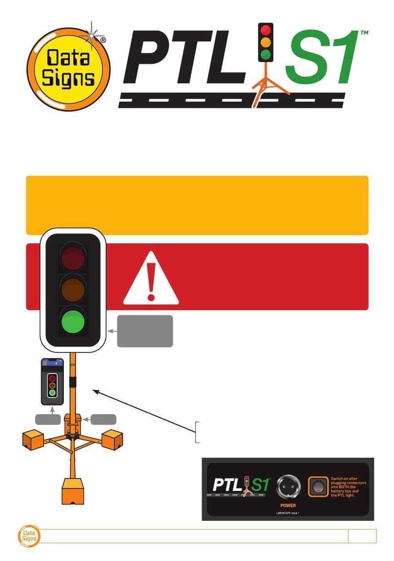
Data Signs PTL Compact 1 User manual

PTL OPERATIONS MANUAL 1
PTL Compact Type 1 Operations
and Maintenance Manual
Your Portable Traffic Lights are compact lightweight traffic lights. As such correct
operation for Set-up and Take-down procedure is essential. Please ensure this
manual is read and understood before attempting to operate the Data Signs’ Portable
Traffic Lights (PTL).
Set-up and Maintenance requirements of the PTL are covered by this Manual.
CAUTION:
The Data Sign Portable Traffic Lights should only be operated by qualified
traffic managers.
If you have hired out this PTL, contact the Hire Company for assistance.
The PTL Compact TYPE 1 is
intended to be used to control
localized vehicular traffic flow
as a safer substitute for STOP/
SLOW (lollipop) signs. It does
not incorporate features such as
Vehicle Detection or solar powered
operation.
It is powered by a LiPo maintenance
free battery that needs to be
recharged at the end of the day. It is
not intended to be left unattended
on site and can only be operated via
the Remote Control which places
a safe distance between the actual
Traffic Light and the operator.
An overview of the layout of
the PTL Compact equipment is
provided here.
© 2020 Data Signs Pty Ltd. All rights reserved |UNCONTROLLED WHEN PRINTED |MAN 0019I Issue 3 |Rev: 22-05-2020
Beacon
Lantern
Shroud
Adjustable
Post
PTL Controller
Battery
PTL Remote
Stabiliser
Legs x 3
Aspects
Battery
Charger
Key Switches
Optional
Target Board

DATA SIGNS AUSTRALIA PTY LTD
2
Installation - Setting Up for Operation
Complete the setup
procedure as per the
steps below.
Suitable location:
Ensure that a level
surface is chosen for
setup.
Once all feet are down,
pull the center post
upwards to lock each
foot into place.
Once the stabilizers are
fixed into position, place
the Control Box onto
the post.
Align the notches in
the control box over the
metal bracket and lower
onto it.
Remove the light from
the carry bag.
Place it on the post
until the pin locks it into
place.
Do this for all sides as
shown.
Push with your feet on
the levers to allow the
stabilizer feet to fall
downwards.
Take care when the
feet fall downwards!
If high winds are
expected, place 20Kg
sand bags on each leg.

PTL OPERATIONS MANUAL 3
Plug in the cable by
lifting the weather
flap and pushing the
connector in, then
pull up the flap until it
‘locks’ over the plug.
Raise light by extending
the post.
Pull out the lower
spring clip, lift lights
until it clicks back in.
Optional Target Board:
This is useful when the
sun is behind the lights.
Switch on the
Controller(s).
Use the PTL Remote to
turn on the lights.
Operate from a safe
distance.

DATA SIGNS AUSTRALIA PTY LTD
4
Both the Master and Slave Controllers are fitted with
ON/OFF key-switches for security reasons, however
operational control is ONLY possible via the Remote
Controller.
Insert the right-side key and turn the switch to the ON
position for both Master and Slave units.
The Master and the Slave controllers will begin to
establish a radio link as indicated by the TX and RX
green lights on the controllers.
The Lights will remain blank until the Remote is
switched on and the Power ON button is held down for 5
Seconds, after this the Lights will show Flashing Yellow
and progress to showing RED, during this process the
Controllers and Lights will complete a self-diagnosis.
SHUTTLE or PLANT CROSSING Control is selected with
the left side key-switch.
GATING MODE which is single light use is selected via
the MAIN MENU Screen. Scroll down until the GATING
CONTROL menu is shown and select ON/OFF.
For Gating Mode see page 11
If PROGRAM selection is activated with the left key-
switch, the Controller will wait for further input and all
connected traffic lights will display blank.
Note: The left side key cannot be removed from the
key-switch while in the PROGRAM position. For safe
operation, remove the keys after the PTL units have been
setup and are operating.
Turning the Controllers On 4
Master Controller: Operational MODE SELECT 5
QuickStart 5
Shuttle Control – Single-Lane Usage 6
Plant-Crossing Control (2-Way) 8
Cycle and Phase Intervals for Shuttle and
Plant Crossing 10
Gating Control 11
Type 1 PTSS — PTL Remote Usage 12
Type 1 PTSS — Startup and Shutdown
using the PTL Remote 13
Type 1 PTSS — Self-Test using the PTL Remote 13
Main Menu 14
Controller display screens for Master and Slave 15
Wireless Link (RF) Explained 16
Fault Conditions 17
Troubleshooting Guide 18
Contents
PTL Compact Controller Type 1 QuickStart Guide
PTL Remote PTL Controller
This QuickStart Guide covers the PTL Controller Operation as per Australian Standards AS-4191:2015 plus QLD MRTS264 and
Various State Authority requirements.
Ensure the units are setup as described in the first section of this booklet. This User Manual applies to Controllers operating on
firmware 05.00.XX or later.
Turning the Controllers On

PTL OPERATIONS MANUAL 5
QuickStart
This MAIN MENU item lets you quickly set up to get the PTL sets going.
1. Master or Slave.
Select Unit 0 (Master) or Unit 1 (Slave)
Press the button to save the selection.
2. Turn the Key switch to Shuttle or Plant Crossing to Begin operation
SETTINGS COMPLETE
T u r n k e y s
w
i t c h
t o d e s i r e d o p e r a t i n g
m
o d e t o b e g i n
Master Controller:
Operational MODE SELECT
Enter PROGRAM selection by using the left key-switch on the Master Controller which
then allows you to select all other controller programmable functions, use the Up or
Down buttons to scroll through the MENU selection, then press the Button to
select the MENU item.
Press the R button to exit the selected MENU.
M A I N M E N U
VIE
W
PTL STATUS
* QUICK START
U N I T S E T T I N G S
Note: The MODE SELECT buttons are not used for Type 1 Compact PTL.

DATA SIGNS AUSTRALIA PTY LTD
6
Shuttle Control – Single-Lane Usage
Shuttle Control is a form of traffic control used where a portion of the roadway is closed
so that only a single lane can be used alternatively by traffic from opposite directions.
Only one Traffic Light unit can show the Green signal phase at any time; either the Master
or the Slave. The diagram below illustrates the traffic control scenario where Shuttle
control would typically be used.
Note: This diagram should not be used as a guideline for setting up a roadwork site, it is
provided as an example only.
Each PTL unit will go to the Green signal phase in turn. See timing diagram later in this
manual.
Shuttle Control is active while the left key-switch on the Master Controller is in the
SHUTTLE position. Operating mode using Shuttle Control is described in more detail on
the following page.
ROADWORKS
SITE
= Rear Flashing Beacon
Unit ID: 0
Unit ID: 1
REMOTE
CONTROL
SHUTTLE CONTROL
These illustrations are intended to outline the different modes which can be used with Data Signs Portable Traffic Lights and should not be used as examples or guidelines on how to setup a
roadwork site − Separate documentation is available for these purposes. Copyright © 2020 Data Signs Pty Ltd. All rights reserved.

PTL OPERATIONS MANUAL 7
SHUTTLE MODE.
This can only be operated via the PTL Remote
Buttons used:
STOP or GO on PTL Remote.
A demand for Green or Red signal phase on the Master or Slave is entered on the Remote
Control unit. For Shuttle Control, on start-up, both the Master and Slave will rest on
Red until a demand for Green is entered.
To enter a demand for either Red or Green, press the STOP or GO buttons on the Remote
Control. The DEMAND LED is activated indicating a demand for either the Master or Slave.
Shuttle Control example:
1. Slave unit is currently showing the Green signal.
2. GO button is pressed for the Master side.
3. If the Green time has expired, the Slave will cycle immediately to Yellow and then Red
signal. The Master DEMAND LED will flash until the Green is lit.
4. Press the GO button on the Slave side to change the Cycle back in the reverse as per above.
5. Note: You can hold BOTH Master and Slave on Red indefinitely by pressing either Red Light.
To return to Green simply select either Master or Slave Green again, the lights will
change when the minimum Red time has expired.
The REMOTE ACTIVE indicator lights up on both the Master and Slave controllers when the PTL
remote is connected.
REAR BEACON LAMP:
The Beacon Lamps mounted behind the Traffic Lights flash on each unit when the Red
Lights are ON.
REMOTE
ACTIVE
PTL Remote Screen
Master / Slave Controller
For display use only

DATA SIGNS AUSTRALIA PTY LTD
8
Plant-Crossing Control (2-Way)
Plant-Crossing control is used to enable both directions of traffic flow along a roadway to
be simultaneously stopped, e.g. to allow road construction vehicles to cross. The diagram
below illustrates Plant-Crossing control usage.
Note: This diagram should not be used as a guideline for setting up a roadwork site, it is only
provided as an example.
Plant-Crossing Control is active while the left key-switch is in the PLANT CROSSING
position on the Master Controller.
REAR BEACON LAMP
The Beacon Lamps mounted behind the Traffic Lights flash on each unit when the Red
lights are ON. This acts as a visual indicator to the Plant (vehicles) Crossing the road that
it is safe to do so.
SIDE / HAUL
ROAD
= Rear Flashing Beacon
REMOTE
CONTROL
PLANT-CROSSING CONTROL
Both units show the same signal phase.
These illustrations are intended to outline the different modes which can be used with Data Signs Portable Traffic Lights and should not be used as examples or guidelines on how to setup a
roadwork site − Separate documentation is available for these purposes. Copyright © 2020 Data Signs Pty Ltd. All rights reserved.
Unit ID: 0
Unit ID: 1

PTL OPERATIONS MANUAL 9
PLANT CROSSING MODE.
This can only be operated via the PTL Remote
Buttons used:
STOP or GO on PTL Remote.
On start-up, both the Master and Slave will rest on Green signal phase for Plant-Crossing
Control until a demand for Red signal is entered by the operator.
The operator can enter a demand for Red signal using either STOP buttons on the Remote.
Both the Master and Slave units will then cycle to Yellow and the Red signal phase.
To change back to Green signal, either the Master: GO or Slave: GO button is pressed.
When the Red time has expired, the lights will cycle back to the Green signal. If the
Master: STOP or Slave: STOP button is pressed and the Green time has not expired, the
DEMAND LED will flash.
Plant-Crossing Control, Manual mode example:
1. Both the Master and Slave are on Green.
2. Either the Master: STOP or Slave: STOP buttons can be pressed on the PTL Remote.
3. If the Green time has expired both the Master and Slave will cycle immediately to
Yellow and then to Red. Otherwise - if the Green time has not expired - the DEMAND
LED’s will flash.
4. Once the Green time has expired, the DEMAND LEDs will extinguish and the Master
and Slave will cycle to Yellow and then Red.
The REMOTE ACTIVE indicator lights up on both the Master and Slave controllers when a
button is pressed on the PTL Remote.
REMOTE
ACTIVE
PTL Remote Screen
Master / Slave Controller
For display use only

DATA SIGNS AUSTRALIA PTY LTD
10
SLAVE SIGNAL DISPLAY
MASTER PHASE
MASTER SIGNAL DISPLAY
GREEN RED
MASTER FLASHING BEACON
SLAVE FLASHING BEACON
SLAVE PHASE
GREEN RED
SLAVE SIGNAL DISPLAY
GREEN PHASE
MASTER SIGNAL DISPLAY
GREEN
MASTER FLASHING BEACON
SLAVE FLASHING BEACON
RED PHASE
RED
LEGEND:
GREEN
1 to 99 seconds
YELLOW
4 seconds
RED
5 to 99 seconds
FLASHING
Beacon
RADIO OR WIRED LINK
RADIO OR WIRED LINK
CYCLE
PLANT CROSSING OPERATION
SHUTTLE OPERATION
Cycle and Phase Intervals for Shuttle
and Plant Crossing Modes
Roadworks
Site
One-Way Road

PTL OPERATIONS MANUAL 11
SLAVE SIGNAL DISPLAY
MASTER PHASE
MASTER SIGNAL DISPLAY
GREEN RED
MASTER FLASHING BEACON
SLAVE FLASHING BEACON
SLAVE PHASE
GREEN RED
SLAVE SIGNAL DISPLAY
GREEN PHASE
MASTER SIGNAL DISPLAY
GREEN
MASTER FLASHING BEACON
SLAVE FLASHING BEACON
RED PHASE
RED
LEGEND:
GREEN
1 to 99 seconds
YELLOW
4 seconds
RED
5 to 99 seconds
FLASHING
Beacon
RADIO OR WIRED LINK
RADIO OR WIRED LINK
CYCLE
PLANT CROSSING OPERATION
SHUTTLE OPERATION
Gating Control Mode
Single PTL unit use only.
Gating Control is used to control the flow of traffic from a single traffic flow direction only.
Note: The Gating Operation Mode can only be selected on a controller set up as a
MASTER, to activate this mode:
1. Switch the left key to PROGRAM MODE.
2. Use the button to Select GATING CONTROL and select ON.
3. Switch the Key Switch back to SHUTTLE position.
To switch off Gating Operation Mode, follow the same process as above, selecting OFF in
step 2.
Gating control can also be used with 2 PTL units operating independently by two traffic
operators using a Walky-Talky to communicate with each other.
GATING CONTROL
OFF
* O N
M A I N M E N U [ T Y P E 1 ]
QUICK START
U N I T S E T T I N G S
* GATING CONTROL
Note: If using 2 PTL Compact in Gating Mode, each PTL must be set on its own unique
channel number as there in NO radio-link communication between each unit and also to
eliminate risk of possible interference between the two units.
In this mode, the line of sight or distance limit does not apply.
Note: Two independent PTL Remotes are required for this operation.
Roadworks
Site
One-Way Road
Normal line-of-sight operation not used
in this setup configuration.
Two-way radios used between traffic
management operators.

DATA SIGNS AUSTRALIA PTY LTD
12
Use the PTL Remote to control, set the Red and Green times,
test or power off (blank) the Lights.
Only the PTL Remote can be used for these functions.
The top of the screen shows the battery level of the PTL
Remote. The signal strength between the Master and the PTL
Remote is also indicated.
The status box shows current operational type and the
countdown timer for the currently displaying Lights.
The main section of the screen shows the state of the
connected devices.
Press the Green or Red Light buttons on the main section of
the screen to change the lights being displayed.
Use the MENU button on the bottom of the screen to open the
SETTINGS menu screen.
From the menu screen, the operator can Power On/Off the
connected PTL Compact units, change the pre-set times,
and request a PTL Compact self-test to be performed on the
connected PTL Compact units.
The RF Channel as well as the STATUS is also selected from
this menu.
Press BACK to return to normal operating mode.
Type 1 PTSS — PTL Remote Usage

PTL OPERATIONS MANUAL 13
Select Type 1 Power On/Off from the menu.
To startup from shut down state, press the button on the
screen for 5 seconds. Alternatively, to startup from an inactive
state, use the same button and press for 5 seconds.
In shutdown state, the lights are disabled and the LCD’s on the
PTL Controllers are turned off.
When the SELF TEST button is pressed, the following
sequence is run on the PTL Compact to test the aspects, on
any connected units:
Green signal, yellow signal, red signal and blank for 0.2
seconds.
Note: the Red and Green Times are reset to the default times
of Green = 1 Seconds, Red = 5 Seconds.
Type 1 PTSS — Startup and Shutdown
using the PTL Remote
Type 1 PTSS — Self-Test using the
PTL Remote
It is advisable that the self-test not be carried
out while the PTL Compact are setup on the
roadway.
SETTING THE RF CHANNEL ON THE REMOTE CONTROL.
To set the RF Channel on the Remote Control, follow these instructions.
1. Press the MENU button on the bottom of the screen to go to settings.
2. Press the RF Channel option.
3. Enter the new channel number.
4. To re-start normal operation, press the BACK button.

DATA SIGNS AUSTRALIA PTY LTD
14
MAIN MENU
On Master or Slave Controllers.
While the Controller is in the PROGRAM setting, use the Up or Down buttons to
navigate forward and back through the MENU’s to select all other programming functions.
MENU: VIEW PTL STATUS
When this menu item is selected, all the current settings and status of the PTL controller
are shown.
Use the Up or Down buttons to navigate forward and back through the list.
MENU: QUICK START
Use the Quick Start Menu item, this will guide you through the process to set the Master
or Slave.
MENU: UNIT SETTINGS
Use this menu to set the Unit ID and Communications settings.
SUBMENU: ID
For the PTL-Type-1 this is the same function as QUICK START.
MENU: OPERATING SETTINGS [Master only]
WIRELESS LINK (RF)
Enter the RF channel then press the button.
Note: you will also need to change this value to match on the other unit(s) communicating with a
Master unit.
MENU: FAULT LOG
Sub-menu: VIEW LOGS
Select this menu item to scroll through the fault log file.
More information regarding the fault log file is provided in the Fault Conditions section of this manual.
Sub-menu: ERASE ALL
Selecting this menu item deletes the fault log file that is stored on the SD memory card
MENU: ASPECT TEST
Press Master Red, Yellow, Green or Slave Yellow for Beacon Lights. Press button to exit.
MENU: FACTORY SETTING
This menu item is restricted to Data Signs internal factory use.
For GATING CONTROL see section on page 11.

PTL OPERATIONS MANUAL 15
Controller display screens for Master
and Slave
Master ID=0 The following values will be shown on the display panel during normal
operation
1 4 . 2 V S I G : 5
TYPE 1 PTSS MASTER
NORMAL ALL RED
C H N : 2 0 0 0 S e c
First line: Master Battery Voltage. Right side, Slave Battery Voltage. & Signal Strength
Second line: Shows TYPE 1 PTSS.
Third line: Control Type (i.e. NORMAL). Right side, Current light sequence
Fourth line: Current RF Channel. Right side, Current state remaining time
Slave ID=1. The following values will be shown during normal operation:
U N I T I D : 1 1 3 . 3 V
CHN : 2 SLAVE
CONNECTED TO : PTLD2
T I M E O U T I N : 0 2 S e c
First line: The ID of this unit. Right side, current Battery Voltage.
Second line: RF Channel set on this unit.
Third line: The Serial Number of the Master Controller this unit is connected to.
Fourth line: The current RF timeout value. If this starts to count down there are
interruptions to the RF communications.

DATA SIGNS AUSTRALIA PTY LTD
16
Each Traffic Light is fitted with an aerial located on the top of the control box. This will provide
Wireless Radio (RF) communication between the PTL units; however, the units still need to be
positioned in line-of-sight to each other.
The maximum distance is about 800m, depending on surrounding environment.
The radio link module fitted to the PTL unit communicates on one of eight channels. This
must be set to the same channel on each unit to maintain wireless communication. This
applies to the Master, Slave, and the Remote Control.
Radio Link Operation
If the radio link between the Master and a Slave unit is disrupted for a continuous 2 second
period (the default time) all units will revert to red lights and “CONTACTING SLAVE…” will be
shown on the display panel on the Master Controller.
Signal Strength
The Remote Control will display the signal strength of the Master Controller to the PTL
Remote as a Graphic symbol in the top right corner on the display. The Master and Slave
Controllers display the Signal Strength and the Battery Level on the display. The RF Signal
Strength is a value out of 5, where 5 is the strongest value.
Wireless Link (RF) Explained

PTL OPERATIONS MANUAL 17
If any fault conditions occur as discussed throughout this document, the Portable Traffic
Lights will go to Red.
The faults logged are outlined below. Reference back to the Australian Standard is provided
in the table.
Fault ID Description
0Yellow
1Red
2 Green
3 Beacon
6 Excessive Link
7 Conflicting Link
8 Link Timeout
10 Low Battery
11 Tilt
To view the current fault log file, select FAULT LOG VIEW LOGS from the
Mode menu. Use the and arrow buttons to move through the fault log entries.
The last fault logged is shown first.
A sample fault log entry may be:
F A U L T L O G ( 1 / 1 )
XX/XX
/
X X X X 0 0 : 0 0 : 1 4
0 0 - M A S T E R
Y e l l o
w
( O p e n )
The time shown with each fault log entry is the time that this fault occurred since the Master
Controller was powered up. The second part is the Portable Traffic Light unit affected (i.e.
Slave#2 or Master). The last part of the entry is the fault description.
Note: The XX/XX/XXXX is not used for PTL Type-1.
You can also use an SD card reader on a laptop/PC to read the fault log files from the SD
card. The file will be in the LOGS directory on the SD card.
Fault Conditions
All critical faults are logged to a file on the SD card fitted to the Master Controller.
Turn the Master Controller OFF and remove the SD card from its slot, leave the power
OFF while re-inserting the SD card.

DATA SIGNS AUSTRALIA PTY LTD
18
This section contains some tips on handling some of the issues that may arise when using
the Traffic Lights. If you cannot resolve the issue you are experiencing using the information
below, please contact Data Signs on the Help Desk Via the Web site. As discussed above, the
Fault Log stored on the SD card in the Master Controller may assist in issue diagnosis.
Turning the Controller On
If the POWER light does not come on when the key-switch is turned to ON:
• Check that the controller connector is inserted properly.
• Check the fuse inside the Controller and on the battery fuse board.
• Check that the battery voltage is above 10.5 Volts.
Radio Wireless Link failure
If the radio wireless link fails regularly, try changing the Channel set on all Controllers, as
some interference may be occurring on the operating channel. Power-cycle each unit after
the Channel has been set correctly
SD Card Failure
In the case of SD card failure, you will be notified on the display. Default values will be used if
the SD card fails. All parameters can be changed, however they will not be saved, so you will
need to enter your desired parameters each time the Master Controller is turned on, until the
SD card is replaced.
Lights Not Working
Check the connections on the controller or the lights.
If you need to ship the Controller or parts back to Data Signs for repair, contact the
Help-Desk at datasigns.com.au/ServiceSupport/HelpDesk
Troubleshooting Guide
Never insert or remove the SD-Card with the power on, switch key
to OFF first.
Note: If shipping Controllers it is recommended to ship as a set, i.e. Master, Slave and
Remote. It will benefit to ship all these items as this will enable our service department to
perform a full operational test and diagnosis.

PTL OPERATIONS MANUAL 19
This manual complies with the Specification MRTS264 Type-1 Portable Traffic Signals and
where relevant AS4191-2015 Portable Traffic Signals.
Each state or territory has its own guidelines and training or accreditation requirements for
the use of the DataSign-PTL-COMPACT on public roads, particularly for road works usage.
The usage and training requirements are outside the scope of documentation provided by
Data Signs. The list below serves as a guide only; please contact the road traffic authority in
your state or territory for more information.
• In New South Wales, refer to the Traffic Control at Work sites document released by
the RTA/RMS. Note the training requirements in section 2.4.
• In Victoria, refer to the Road Management Act 2004 – Worksite Safety – Traffic
Management, Code of Practice for guidance on the use of the DataSign-PTL on roads
in Victoria. Note the training requirements.
• In Queensland, see the Traffic and Road Use Management (TRUM) manual that
is issued under the authority of Section 166 of the Transport Operations (Road
Use Management) Act 1995. Also see the Manual of Uniform Traffic Control Devices
(Queensland), which within the meaning of the Transport Operations (Road Use
Management) Act 1995, contains the design of, and the methods, standards and
procedures in relation to every sign, signal, marking, light or device, installed on a
road. Training requirements are available from the Main Roads QLD website.
• In Western Australia, see the Traffic Management for Works on Roads - Code of
Practice. Note the accreditation requirements. Also see the Traffic Controllers’
Handbook.
• In South Australia, there is a Work zone Traffic Management course.
• Generally, the Australian Standard AS 1742.3–2002: Manual of Uniform Traffic Control
Devices, Part 3: Traffic Control Devices for Works on Roads should also be consulted.
Suggestions & Improvements
Data Signs develops its products with the end users in mind. As such, we are always open
to suggestions for product improvement. Contact Data Signs, Head Office in Australia at:
datasigns.com.au
Disclaimer
The information contained in this document is proprietary information of Data Signs Pty Ltd
unless otherwise indicated. Data Signs Pty Ltd make every effort to ensure the quality of the
information it makes available. Notwithstanding the foregoing, Data Signs Pty Ltd does not
make any warranty as to the information contained herein and does not accept any liability
for any injury, loss or damage of any kind incurred by use of or reliance upon the information.
Data Signs Pty Ltd reserves the right to make modifications, additions and deletions to this
document at any time and without notice.
The Data Signs logo is a registered trademark of Data Signs Pty Ltd in Australia, New Zealand,
United Kingdom, India and United States of America, and a trademark in other countries.
This manual suits for next models
2
Table of contents
Other Data Signs Safety Equipment manuals

