Surewerx Peakworks Rope Grab RG-11010 User manual

Rope Grab
READ CAREFULLY
BEFORE USE
Certied to:
CSA Z259.2.5-2012
ANSI Z359.15-2014
ENGLISH
M16-PW Rope Grab EN-FR 06-2016
A / Une / Una
Brand / Marque / Marca
surewerx.com
Un partenaire
A
Partner
Canada:
SureWerx, 49 Schooner St.,
Coquitlam, BC V3K 0B3
surewerx.com
USA:
Sellstrom Manufacturing Co.,
Schaumburg, IL 60173
sellstrom.com
Made in China
Fabriqué en Chine
Hecho en China


INTRODUCTION
INC
TM
WWW.PEAKWORKS.CA
2
This manual contains the Manufacturer’s Instructions as required by CSA Z259.2.5 and
ANSI Z 359.1. It should be used as part of the fall protection training program required
by law. All PeakWorks’ products are designed and engineered to meet or exceed
applicable CSA and ANSI standards along with labour ministry requirements.
WARNING: All persons using this equipment must read and understand
all the instructions and warnings contained in this manual. Failure to do so
may result in serious injury or death. Do not use this or any other fall
protection equipment unless you have been properly trained.
FALL PROTECTION
It is the employer’s responsibility to provide fall protection and training for any worker
deemed to be working at height. In Canada, any worker that is more than 3 meters from
the ground or first obstruction must have fall protection.
SYSTEM COMPATIBILITY
PeakWorks equipment has been designed and approved for use only with PeakWorks
connectors. Any substitution of components may result in compatibility issues. Users
should always ensure that the connectors are properly selected and connected so as not
to allow a load to be applied to the gate of the connector.
WARNING: Not following either of these instructions could result in the fall
protection system becoming disengaged during a fall which could result in
serious injury or death.
TRAINING
All workers and their employer must be trained in the correct use, care and maintenance
of this and any other fall protection equipment used. It is the employer’s responsibility to
provide proper fall protection training for all workers using fall protection equipment. Both
the worker and the employer must be aware of the correct and incorrect applications and
use of this equipment.
WARNING: Failure to be properly trained on this equipment and any other fall
protection equipment used in conjunction with this equipment could result in
serious injury or death.
RESCUE PLAN
A rescue plan is an integral and critical part of any fall protection plan and system. It is
the responsibility of the employer to have a rescue plan prepared by a competent person.
All workers using any fall arrest system must have a rescue plan prior to using the
system.
INSPECTION
WARNING: If any portion of the inspection reveals problems, deficiencies or
unsafe conditions, the equipment must be removed from service immediately.
This equipment and any other fall protection equipment used in conjunction with it should
be inspected by the worker every time it is used. This equipment must be inspected annu-
ally by a competent person. A competent person is defined by OSHA: “By way of training
and/or experience, a competent person is knowledgeable of applicable standards, is
capable of identifying workplace hazards relating to the specific operation and has the
authority to correct them”. Details of how to inspect this equipment is discussed later in
the manual.
FALL CLEARANCE
INC
TM
WWW.PEAKWORKS.CA
3
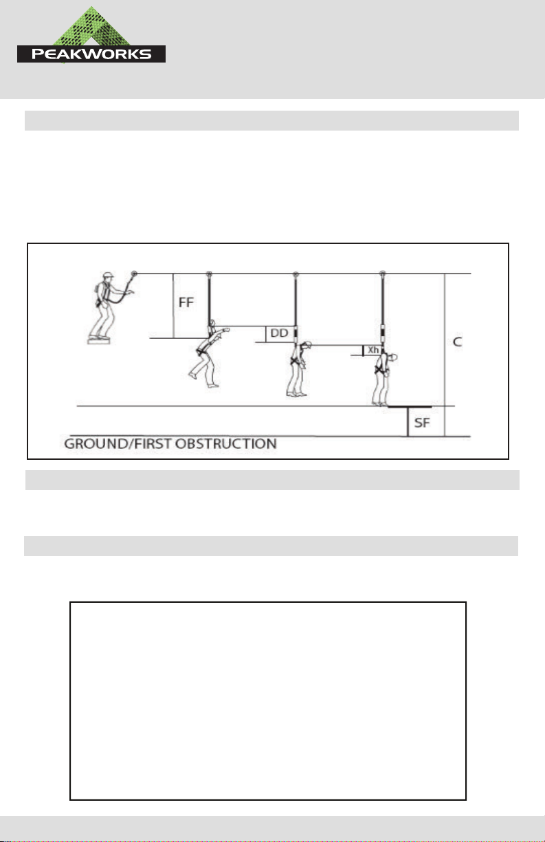
Fall Clearance is the distance required to safely arrest the users fall. It is the distance from
the anchorage to the ground. A Fall Clearance Calculation must be done anytime this or
any other fall protection equipment is use.
Step 1: Calculate Free Fall (FF)
Step 2: Determine how much the connecting device deploys (DD)
Step 3: Determine the stretch of the harness (Xh)
Step 4: Add a safety factor (typically is 3 ft)
Step 5: Fall Clearance C= FF +DD + Xh + SF
REPAIR
Do not attempt to repair or alter this fall protection equipment. Repairs can only be
performed by the manufacturer or its authorized agents.
TABLE OF FALL PROTECTION STANDARD
Fall protection equipment is governed in Canada by the Canadian Standards Association
(CSA) and in the United States, the American National Standards Institute (ANSI)
Canadian Standards Association Fall Protection Standards:
CSAZ259.1-05(R2010) Safety Belts and Saddles for work positioning and travel restraint
CSA Z259.2.2-98(R2009) Self-Retracting Devices for Personal Fall-Arrest Systems
CSA Z259.2.3-12 Descent Control Devices
CSA Z259.2.4-12 Fall Arrester and Fixed Rigid Rails
CSA Z259.2.5-12 Fall Arresters and Vertical Lifelines
CSA Z259.10-12 Full Body Harness
CSA Z259.11-05(R2010) Energy Absorbers and Lanyards
CSA Z259.12-11 Connecting Components for Personal Fall Arrest Systems
CSA Z259.13-04(R2009) Flexible Horizontal Lifelines
CSA Z259.14-12 Fall Restrict Equipment for Wood Pole Climbing
CSA Z259.15-12 Anchorage Connectors
CSA Z259.16-04(R2009) Design of Active Fall Protection Systems
ANSI Standards:
Construction and Demolition Operations:
Z359.1-2007 Safety Requirements for Personal Fall Arrest Systems,
Subsystems and Components

ROPE GRAB OVERVIEW
INC
TM
WWW.PEAKWORKS.CA
4
All PeakWorks’ rope grabs have been designed and engineered to meet or exceed all applicable
standards and Ministry of Labour requirements.
ROPE GRAB CAPACITY
PeakWorks rope grabs are designed for use by persons with a combined weight (clothing, tools, etc.)
of no more than 300 lbs. Make sure all of the components in your system are rated to a capacity appro-
priate to your application.
ROPE GRAB CLASSIFICATION
The RG-11010, RG-11000 & RG-21000 Rope Grabs are automatic panic type rope grabs
class ADP (Automatic-Dorsal-Panic) and are designed to be part of a personal fall arrest system.
The rope grab is designed to follow the worker automatically. In the event of a fall, the rope grab
will lock onto the rope and arrest the fall. This rope grab is designed with a panic feature. In the
event the worker has fallen and “grabs” onto the eye of the rope grab, the secondary
mechanism will engage and the worker’s fall will be arrested.
LABELS
This rope grab has product labels and fall indicator labels.
ROPE GRAB COMPATIBILITY
ROPE GRAB PERFORMANCE DATA
MAXIMUM ARRESTING FORCE…………………………………………………1800 LBS (kN)
MAXIMUM STOPPING DISTANCE………………………………………………39” (1 M)
CAPACITY……………………………………………………………………………………300 LBS (WITH TOOLS)
RG-11010 & RG-11000 COMPLY AND ARE CERTIFIED TO………CSA Z259.2.5
If the rope grab does not come with an integral lanyard, the user must connect to the O-ring using
only an approved and compatible connecting device no longer than 30" (750 mm).
The RG-11010 & RG-11000 Rope Grabshave been designed and certified with the following vertical
lifelines:
5/8” (16 mm) Co-Polymer 3-strand Twisted Rope – PeakWorks Part # VL-1115-XX or VL-1122-XX or
VL-1125-XX or VL-1145-XX or VL-1815-XX or VL-1825-XX or VL-1845-XX.
The RG-21000 Rope Grab has been designed and tested with the following vertical lifelines:
5/8” (16mm) diameter Prosteel rope (62145) – PeakWorks Part # VL-1115-XX or VL-1122-XX or
VL-1125-XX or VL-1145-XX or VL-1815-XX or VL-1825-XX or VL-1845-XX.
WARNING: Do not connect this rope grab with a form hook
ANCHORAGE STRENGTH
Each Fall Arrestor must be connected to a vertical lifeline that is anchored to a suitable structure
capable of resisting a static load of 3,600 lbs (16 kN) if certified, or 5,000 lbs (22.2 kN) if not certified.
If more than one vertical lifeline is anchored to the structure, the structure must be capable of resisting
static loads equal to the above values multiplied by the number of vertical lifelines attached to it.
Every anchorage point must be selected with care. The anchorage point
location, in combination with the lanyard, should never permit a free fall of more
than 6 ft. (1.8 m). Always check for obstructions below the work area to make
sure that the potential fall path is clear. When selecting an anchorage point,
take into consideration that a deceleration device, such as a shock absorber, can
elongate up to 42 in. (1.1 m) and the deceleration of the rope grab along the
lifeline could be up to 39 in. (1 m).
Always work directly under the anchorage point to avoid a swing fall injury.
RG-21000 COMPLIES AND IS CERTIFIED TO……………………………CSA Z259.2.1

INC
TM
WWW.PEAKWORKS.CA
5
CARE AND STORAGE
This rope grab and all fall protection equipment should be stored in a clean dry environment that is
free of exposure to fumes or corrosive elements. If the rope grab is being used in a corrosive environ-
ment (for example near salt water), the rope grab must be inspected more frequently. Any build up of
dirt or grime can seriously reduce the performance of the rope grab and in some cases may prevent
the rope grab from arresting a fall.
Regular cleaning of your rope grab will ensure proper performance and will help extend its life. Clean
your rope grab in a mild solution of water and mild soap or detergent. Wipe the rope grab dry with a
clean cloth. Do NOT lubricate the rope grab.
INSTALLATION (RG-11010 & RG-11000 Model Rope Grabs Only)
Installing rope grab on rope
STEP1: Ensure the rope grab is positioned so that the “UP” arrow is facing upwards.
STEP 2: The rope grab is designed with an orientation lock out and will not open if the rope grab is not
in the correct orientation (i.e. facing upward) (see figure 1).
STEP3: Depress spring-loaded lever and at the same time turn the knurl knob counter clockwise until
the rope grab opens up.
STEP 4: Install the vertical lifeline in the cavity as shown (see figure 2).
STEP 5: Close the side plate of the rope grab ensuring that the rope is seated in the cavity and is not
pinched by the side plate.
STEP 6: With the spring lever depressed, rotate the knurl knob clockwise until the two side plates are
seated firmly against each other without any visible gap. Release the lever to lock.
STEP 7: Test the operation of the rope grab by pulling firmly down on the rope. The rope grab
should lock onto the rope firmly.
STEP 8: If the rope grab does not lock onto the rope repeat steps 1-7.
NOTE: Certified for use on rope with slopes of 0 to 90 degrees.
FIGURE 1 FIGURE 2
INSTALLATION (RG-21000 Model Rope Grabs Only)
STEP 1: To open the fall arrestor, pivot the locking clip away from the body then turn locking screw
counter-clockwise till disengaged then pivot open. Inspect as outlined in section 7.
STEP 2: Position rope grab with arrow pointing up. On RG-21000 models the roller attached to hinge
pin will be pointed down.
STEP 3: Insert the lifeline. Only 5/8” (16mm) diameter Prosteel rope (62145)
should be used. (See
lifeline section following.)
STEP 4: Pivot the ring so that the gripper does not press against the rope then close the unit around
the rope.
STEP 5: Tighten the locking screw. It should thread easily and tighten against the rope grab body with
body parts touching. Rotate the locking clip over the detent (dimple) into the notch in the body. It
should move easily and be held in the locked position by a combination of the detent and bronze thrust
washer. Be sure the screw is tight and clip is fully in the locked position.
STEP 6: Test the operation of the rope grab by pulling firmly down on the rope. The rope grab should
lock onto the rope firmly.
STEP 7: If the rope grab does not lock onto the rope repeat steps 1-6
NOTE: Approved for use on rope with slopes of 0 to 90 degrees.
WARNING: Use only 5/8” rope specified in this manual. Use of any other rope or diameter
is prohibited and would result in serious injury or death.
INC
TM
WWW.PEAKWORKS.CA
6
INSTALLATION TESTING
STEP1 : Mobility Test
This rope grab was designed to function with a minimum of effort on a weighted co-polymer vertical
lifeline. With the vertical lifeline held taught with a 6-10 lbs weight or by securing the lifeline at the
bottom, move the rope grab upward by pulling up on the rope grab lanyard or shock absorber. The rope
grab should move easily upwards. Move downward by lifting up on the lanyard or shock absorber
enough to release the gripper and allow the weight of the unit to move the rope grab downwards.
Repeat to ensure the freedom of movement.
STEP 2: Lock Off Test
Test the fall arrestor installation by pulling down sharply on the lanyard or continuous energy absorbing
lanyard to ensure that the mechanism locks onto the rope.
ROPE GRAB USE
The rope grab is designed to automatically follow the worker as he/she ascends and descends. The
rope grab will always be positioned below the workers fall arrest d-ring, the length of the connecting
device. The worker must ensure that the connecting device (such as a fixed lanyard) does not induce
a free fall greater than what is acceptable in their local jurisdiction.
The worker should always avoid having the vertical lifeline come in contact with sharp edges. All sharp
edges should be protected, to prevent the lifeline from being frayed, abraded or cut.
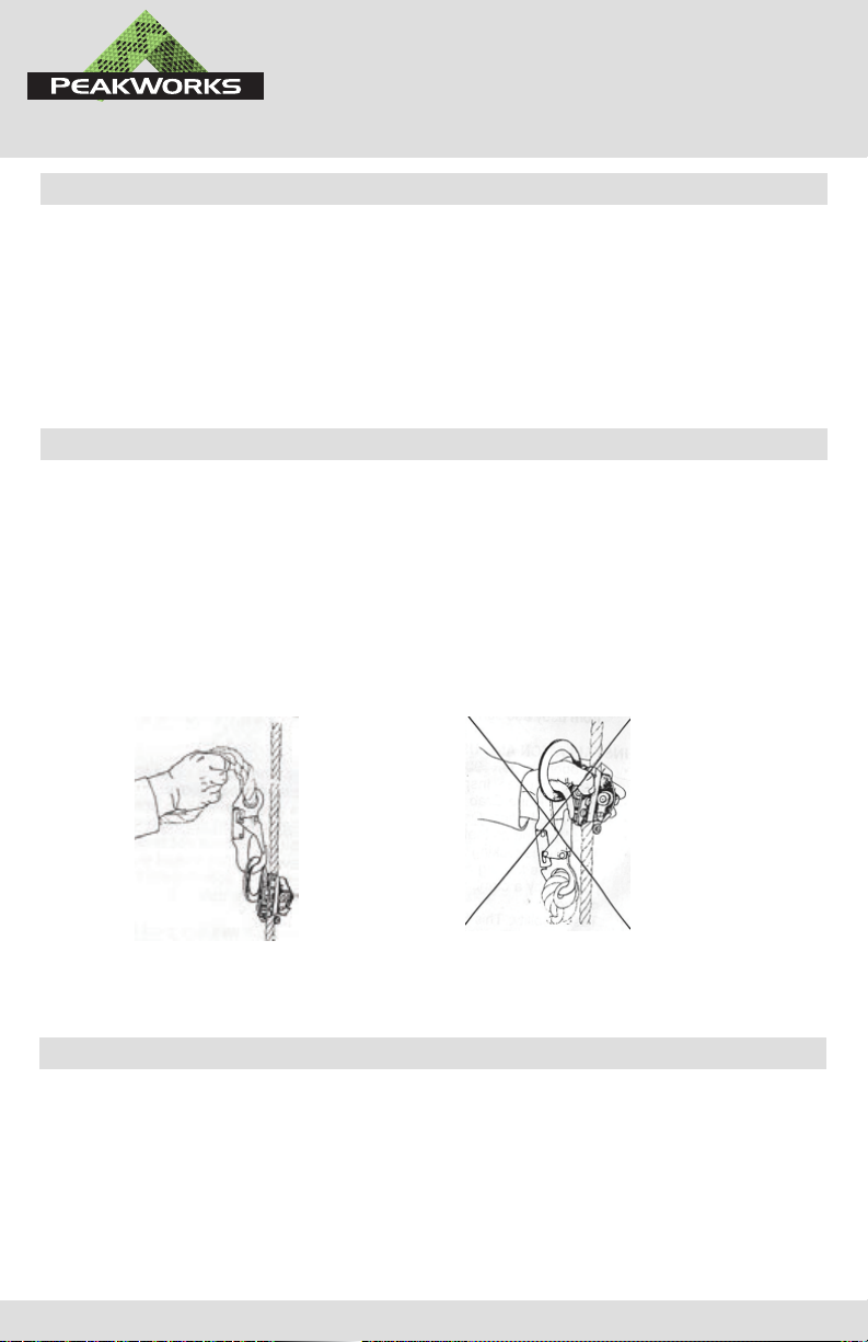
WARNING: When in use, do not reposition/move the unit by holding on to the body of the rope grab. If a
worker should fall while holding the body of the rope grab, they may be restraining the locking mecha-
nism, rendering it unable to arrest the fall. Serious injury or death could result. See FIGURE 3 AND 4
FIGURE 3
Correct repositioning
of rope grab
FIGURE 4
INCorrect repositioning
of rope grab
ROPE GRAB INSPECTION
This rope grab and any other fall protection equipment used in conjunction with it should be inspected
by the worker every time it is used. This equipment must be inspected annually by a competent person.
PeakWorks offers a professional RFID based inspection system. Please contact PeakWorks for more
information. The following guide should be used to inspect your rope grab.
Warning: If the rope grab has arrested a fall or been subjected to any impact forces, it
must be removed from service immediately and destroyed.

INC
TM
WWW.PEAKWORKS.CA
7
STEP 1: Inspect the o-ring handle and cam for freedom of motion. The handle should be able to move
freely without binding or sticking. The handle must be firmly secured with the rivet so that there is no
movement between the o-ring and the handle.
STEP 2: Inspect the panic cam for freedom of motion. The cam should be able to move freely without
binding or sticking. The cam must be firmly secured with the rivet so that there is no movement
between the cam and the body.
STEP 3: Ensure the orientation lock out is free from burrs, dents, or cracks. Ensure the orientation lock
out moves freely up and down the hinge as the rope grab is rotated upside down and right side up.
STEP 4: The housing locking mechanism consist of two components
1. Spring lever: Ensure the spring lever is pushing the lever into the cavity in the housing of the rope
grab. Depress the lever several times to ensure it functions properly. Remove dirt and/or grime from
the spring if necessary.
2. Knurl knob: Ensure the knurl knob is free from cracks, dents, or burrs. Insert pin into threads and
run the knob in and out of the threads to ensure the rope grab closes properly.
STEP 5: Ensure roller rotates freely and is free from cracks, dents, or burrs.
STEP 6: Ensure the body of the rope grab is free from corrosion, cracks, dents, or burrs. Ensure that
when the rope grab is closed that the two side plates mate properly and there is no visible gap.
STEP 7: Ensure the hinge pin is free from corrosion, cracks, dents, or burrs and is not bent. Ensure
the hinge pin allows the side plate to close without binding. Ensure the rivet is not damaged and
secures the hinge pin from moving.
STEP 8: Ensure that all labels and markings are present and legible. All labels and markings are
included in the instruction manual as a guide.
PRODUCT LABELS
INSPECTION LOG
INSPECTION CORRECTIVE MAINTENANCE INSPECTION
INSPECTION
DATE RESULTS
CORRECTIVE
ACTION
MAINTENANCE
PERFORMED
INSPECTION
CONDUCTED BY
1
2
3
4
5
6
7
8
9
10
This manual suits for next models
2
Table of contents
Other Surewerx Safety Equipment manuals


Popular Safety Equipment manuals by other brands


Rockwell Automation
Rockwell Automation Allen-Bradley GuardShield 450L-B4FNxYD user manual

Gin
Gin Switch harness owner's manual

3M
3M DBI SALA NANO-LOK 3101580 User instructions

Eaton
Eaton FlexiTech manual

TEUFELBERGER
TEUFELBERGER VOLTA Manufacturer's information and instructions for use

Leuze
Leuze MLDSET-M1-1600T4 manual