EN
page 26
INSTALLER SECTION
1.4 Electrical connection
The electrical connection must be made according to current technical standards.
Ensure that the mains voltage corresponds to the value given on the machine dataplate.
It is necessary to install a suitable omni-polar automatic fuse switch sized according to the absorption
that assures the complete disconnection from the network in an overvoltage category III condition.
This switch must be incorporated in the supply network, dedicated only and exclusively to this circuit and installed
in the immediate vicinity.
The machine has to be absolutely turned off by this switch: only this switch gives the full warranty of complete
detachment from the electric network.
Make sure the appliance is linked to an effi cient ground connection.
On the back of the appliance there is a terminal marked with the symbol , which is provided for equipotential
connection between diff erent appliances (see electrical safety standards).
1.5 Temperature adjustment
If necessary, the water temperature of the wash and rinse cycles can be adjusted by means of the fi ne-adjustment
screws on the respective thermostats.
The recommended temperatures are 55°C for the wash cycle (tub) and 85 - 90°C for the rinse cycle (boiler).
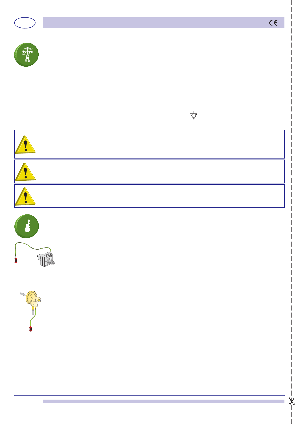
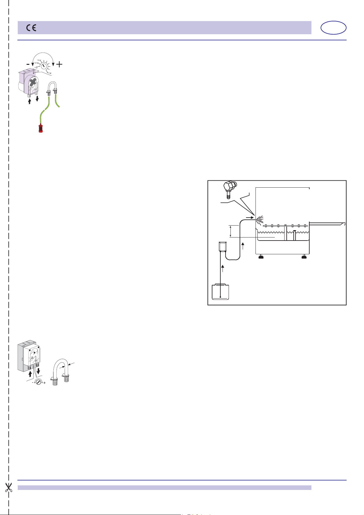
1.6 Rinse aid dispenser operation (pict. 1 - 2)
Operation: It utilizes the diff erence in combined pressure caused by turning the washing pump on and
off , and the rinse pressure.
Water connection:
1) Connect the dispenser tube fi tting A to the pump, by means of the rubber tube installed in the
appliance (pump pressure).
2) Connect the small black rubber tube by the brass delivery fi tting B to the connection in the boiler
(injector).
3) Make sure that the green product suction tube is inserted on the special fi tting C and that the small fi lter
and the ballast are inserted in the rinse aid tank.
Priming: To prime the dispenser, turn on the appliance and carry out several complete wash cycles.
Adjustment: With each rinse cycle, the dispenser draws an amount of rinse aid, adjustable from 0 to 4
cc, equivalent to a length of 0 to 30 cm drawn into the suction tube.
In order to regulate the dispenser to the minimum amount, turn the adjustment screw D completely clockwise.
For the maximum amount, turn the screw anticlockwise about 20 complete turns.
For the correct amount of rinse aid, see the paragraph 5.3 Use of rinse aid.
Note: for each turn of the screw the amount of the product drawn into the tube varies by 1.6 cm, equivalent
to 0.2 cm³/turn (about 0.21g/turn with a concentration of 1.05 g/cm³ of rinse aid). The rinse aid cannot function properly if
the diff erence in level between the bottom of the machine and the container exceeds 80 cm.
THE DISPENSERS ARE PRE-SET TO A 5 CM OF TUBE (0,65 gr.) INTAKE OF PRODUCT FOLLOWING A TEST PHASE
SYSTEM CHECK. THIS MEASUREMENT SHOULD BE ADJUSTED ACCORDING TO THE TYPE OF RINSE AID USED
AND WATER HARDNESS.
C
D
B
A
code 10799
pict. 1
code 10799/G
pict. 2
C
D
B
A
WARNING: check very carefully if the “ground connection” of the machine is properly sized and fully effi cient, and
that not too many units are connected to it. An undersized or poor “ground connection” might lead to corrosion
and/or pitting eff ect on the stainless steel plates, even to perforation.
FOR APPLIANCES USING A THREE-PHASE POWER SUPPLY, FOLLOW THE INSTRUCTIONS AND WIRING
DIAGRAM ATTACHED TO THE APPLIANCE.
ATTENTION TO CORRECT SENSE OF TRI-PHASES PUMPS ROTATION (if present).
Feed cable: the retailer - importer - installer must ensure that the feed cable complies with the cable insulation
category of the workplace, in conformity with current Technical Standards.