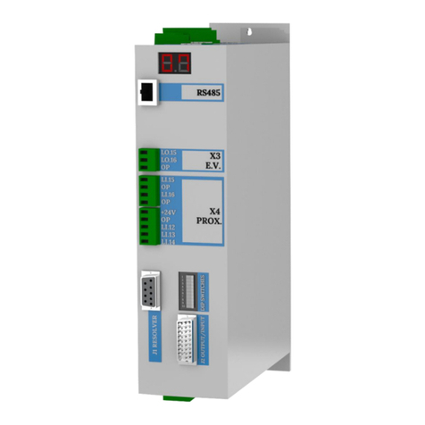
Baruffaldi DB-21 Guide

INSTALLATION AND USE MANUAL
SERVO DRIVE TYPE –DB21
M.DRIVE.DB-21.GEN.ENG
Ed.
2022
Rev.11
Pag.
1 di 34
INSTALLATION AND USE MANUAL
Servo Drive type DB-21
Suitable for turrets models:
Linea Archimede: TB/TBMA/TBMR
Linea Michelangelo: TAB
Linea Leonardo: TC/TCMA/TCMR
Linea Galileo: TBHMA-C/TBHMR-C
Linea Ecoline: TBH/TBHMA

INSTALLATION AND USE MANUAL
SERVO DRIVE TYPE –DB21
M.DRIVE.DB-21.GEN.ENG
Ed.
2022
Rev.11
Pag.
2 di 34
1SAFETY AND INSTALLATION_____________________________________ 4
1.1 SAFETY CONSIDERATION AND INSTALLATION CONSTRAINS__________________________ 4
1.2 EMC ADVICES _______________________________________________________________ 4
1.3 SPECIFICATIONS_____________________________________________________________ 6
2. ELECTRICAL CONNECTIONS ____________________________________ 7
3. DRIVE AND TURRET LAYOUT____________________________________ 8
4. TURRET CONNECTIONS _______________________________________ 9
4.1 LINEA ARCHIMEDE –TB/TBMA/TBMR/TBYA/TBYR (STANDARD ELECTRICAL BOARD ON THE
TURRET) ___________________________________________________________________ 9
4.2 LINEA ARCHIMEDE –TBMR/TBYR (HARTING CONNECTOR) _________________________ 10
4.3 LINEA MICHELANGELO - TAB (STANDARD ELECTRICAL BOARD ON THE TURRET) _______ 11
4.4 LINEA LEONARDO –TC/TCMA/TCMR/TCMQ (STANDARD WITH PLUG-IN CONNECTORS) _ 12
5. J1 INPUT/OUTPUT __________________________________________ 13
5.1 CONSENT TO WORK_________________________________________________________ 13
5.2 POSITION FEEDBACK ________________________________________________________ 13
5.3 ALARMS___________________________________________________________________ 13
5.4 START COMMAND___________________________________________________________ 13
5.5 OPERATIVE MODE __________________________________________________________ 14
5.6 POSITION REQUIRED ________________________________________________________ 14
6. DIPSWITCH SETTING (FOR TURRET TYPE SELECTION) ________________ 15
7. WORKING LOGIC AND POSITIONING INQUIRY_______________________ 17
8. OPERATIVE MODE___________________________________________ 18
9. DRIVE SET-UP (NEW TURRET INSTALLATION) ______________________ 19
10. DUTY CYCLE (BARUFFALDI/DIN5482 LIVE TOOL TOOLING SYSTEM) ____ 21
11. DUTY CYCLE (BMT/DIN5480/DIN1809 LIVE TOOL TOOLING SYSTEM)____ 22
12. DRIVE ALARM _____________________________________________ 23
13. SERVICE _________________________________________________ 24
13.1 TROUBLESHOOTING _______________________________________________________ 24
13.2 COMPATIBILITY WITH PREVUIOUS VERSIONS ___________________________________ 27
13.2.1 drive and motor timeline _________________________________________________________________ 27
13.2.2 turret serial number identification _________________________________________________________ 27
13.3 DRIVE REPLACEMENT (SET-UP AND SETTING) __________________________________ 28
13.4 MOTOR REPLACEMENT FOR LINEA ARCHIMEDE (TB/TBMA/TBMR) AND LINEA ECOLINE
(TBH/TBHMA) _____________________________________________________________ 31
13.5 MOTOR REPLACEMENT FOR LINEA LEONARDO (TC/TCMA/TCMR/TCMQ) ____________ 32
13.6 RESOLVER ACQUISITION FOR LINEA ARCHIMEDE (TB/TBMA/TBMR) / LINEA ECOLINE
(TBH/TBHMA)/ LINEA LEONARDO (TC/TCMA/TCMR/TCMQ) _______________________ 33
14 CABLE ADAPTER FOR OLD DRIVE INTERFACING___________________________________ 34

INSTALLATION AND USE MANUAL
SERVO DRIVE TYPE –DB21
M.DRIVE.DB-21.GEN.ENG
Ed.
2022
Rev.11
Pag.
3 di 34
GENERAL WARNINGS
Before setting at work, carefully read instructions for use and follow them!
Only qualified personnel, that has carefully read instructions, is allowed to operate on tool holder
turrets.
Responsibility and warranty are excluded if:
-Instructions for use are not followed.
-The turret is not operated in a correct way.
-Maintenance is not performed correctly and regularly.
-Functional changes of any type are brought without manufacturer’s consent.
-Original spare parts are not used.
This symbol highlights critical operations:
- a wrong procedure can cause damages to the turret
- nonobservance can determine wrong settings at work
- nonobservance can impair operator’s safety
INSTALLATION WARNING
The Drive is pre-set for an input voltage of 400V.
If might be necessary to switch the input voltage to 220V before to turn ON the
drive/machine follow the instructions at the chapter 9.
Dipswitch
ON
OFF
1 2 3 4 5 6 7 8 9 10
220V
400V
Dipswitch
ON
OFF
1 2 3 4 5 6 7 8 9 10

INSTALLATION AND USE MANUAL
SERVO DRIVE TYPE –DB21
M.DRIVE.DB-21.GEN.ENG
Ed.
2022
Rev.11
Pag.
4 di 34
1SAFETY AND INSTALLATION
1.1 SAFETY CONSIDERATION AND INSTALLATION CONSTRAINS
It is important to ensure that cable and connection are carried out by a qualified technician. Wrong
connections can cause damage to the device or generate dangerous situations for the user.
Dangerous voltages can be found inside the drive and on the external clamps, therefore
maximum attention should be paid during all phases of installation and/or maintenance so
that people are not placed in dangerous situations.
►After switching off the drive, the internal components and the output connectors can still be powered for
several seconds. Before doing anything, check with a Voltmeter that there are no dangerous voltages
on the external clamps.
►Between the control signals and the main power supply the insulation is guaranteed only for functional
purposes and not for user safety.
►All the logic signals, besides the power lines, must be protected against the user direct contact.
►During installation or normal operation, do not use damaged cables or spoiled ones.
►Connect to the ground all the shields and the ground cables. Avoid untidy or twisted cables.
►The converter must be installed in vertical position into the cabinet. Ventilation conditions and surrounding
atmosphere must be settled in a way that the converter cannot work without nominal temperature
range (0÷40°C).
►Relative air humidity must be kept below 90%, with no condensation
►A 150mm clearance area must be considered over and under the driver, the drives and 50mm on the sides
in order to guarantee a high cooling efficiency to the fan.
►The converter heat sink can reach high temperature during normal operations. Avoid direct contacts and
remove inflammable components into the closeness of the converter.
►Before proceeding with the setup of the device it is necessary to check the ground connections, network
voltage and the correct connection (according to this manual) of the control signal connections
1.2 EMC ADVICES
All the cables connected to the Drive must be shielded and grounded.
►An insulation transformer on the power line decoupling the drives from the grid is always a high efficiency
EMC barrier.
►Where it is necessary to intersect the lay out between signal cables and power cables, it is better that the
intersections are made with cross angles of 90.
►With cables length over 8/10m is not guarantee a full protection from EMC.
In case of this over length it is necessary to adapt all the measure to guarantee the complete elimination of EMC
and interference in the machine cables, e.g.:
- It is necessary separate the turret cables from other machines cables, using per example separate canalisations
(with a distance of at least 30cm one from the other cable).
- The using of an external shielded wiring harness on the turret cables.
- External line filters are recommended (ie: Arctoronics F.LL.D3.016A.BN.R1 for 10A)

INSTALLATION AND USE MANUAL
SERVO DRIVE TYPE –DB21
M.DRIVE.DB-21.GEN.ENG
Ed.
2022
Rev.11
Pag.
5 di 34
►It is advisable to install the power parts of the motor control unit (drive, transformer, filters and resistances)
in metallic divisions separate from those assigned to command and control devices. If the power supplies of
the power groups are the same as the control apparatus, they should be connected in the same position
(entrance point of the electronic device) in a star configuration.
WITH OTHER DRIVE
The servo amplifiers must not be install
in the venting flow of other devices
ALL SHIELDED CABLES
All the cables must be shielded and
connected to the ground in order to
prevent EMC problems
TURRET CABLE INSTALLATION
It is necessary to separate the turret cables from
other machines cables (e.g separate
canalisations) or the use of an external shielded
wiring harness on the turret cables
TEMPERATURE RANGE
Smooth operations and life of Servo amplifier
module rely on keeping temperature at all
times within the operating range of 0°C to
+40°C. Temperature should then regularly
be checked
150mm
DRIVE CLEARANCE
The Drive must has a clearance of
50mm on the side and 150mm
over/under the drive
VERTICAL POSITION
Servo amplifier module must be installed in vertical
position only. Sideways or horizontal placement should
not be made, as in this way correct heat exhaustion
isnot guaranteed, and failures would occur

INSTALLATION AND USE MANUAL
SERVO DRIVE TYPE –DB21
M.DRIVE.DB-21.GEN.ENG
Ed.
2022
Rev.11
Pag.
6 di 34
1.3 SPECIFICATIONS
PARAMETERS
Power supply
3x230V
3x400V
+10/-15% 50÷60Hz 2KW
Logic power supply
24VDC ±10%
Nominal Current
6Arms
Method of current
control
SPWM, chopper frequency
3÷10 KHz
Motor control method
Torque control, speed
control,
angular position control
Clamp resistance
47Ω/50W
Protection grade
IP 20
LIMITS OF USE
Atmospheric temp.
0/+40°C
Storage
0°C/+60°C
Relative humidity
5-95% *
Altitude
<1000m slm
VOLUME AND WEIGHT
Width
72 mm
Height
278 mm
Depth
164 mm
Weight
2 Kg
FRONT SIDE
REAR SIDE
278mm
fixed screw M4

INSTALLATION AND USE MANUAL
SERVO DRIVE TYPE –DB21
M.DRIVE.DB-21.GEN.ENG
Ed.
2022
Rev.11
Pag.
7 di 34
2. ELECTRICAL CONNECTIONS
X1 (INPUT)
POWER SUPPLY
Power net (L1-L2-L3)
Voltage option 1: 230Vac 3 phase +10/-15%
Voltage option 2: 400Vac 3 phase +10/-15%
Pmin power transformer (for input with 230V) 2KVA
4Arms / 16Arms peak Class S3
Size cable Ømin=1,5mm2
+DB BUS OUTPUT - not is use
-DB BUS OUTPUT - not is use
Protection device RCD (with differential
protection Id= 300mA) type F
+
Thermal magnetic circuit breake (16A) type C
RS485
J1 (OUTPUT/INPUT)
DIGITALS INPUT/OUTPUT
Out 24Vdc x 100mA
In sink 24Vdc ≤5mA
Level H (min): 20VDC (typ.7mA@24VDC,
Vin(max)=30VDC Level L (max): 12VDC
D26sub connector pin used for dialogue
between plc and drives (details page 6)
X5 (OUTPUT)
MOTOR (U-V-W-T)
3 phase shielded cable Ømin=1,5mm2
with ground
J2 (INPUT)
ANGULAR POSITION TRANSDUCER
Use cable with shielded twisted pairs and
external shield Ømin=0,22mm2 up to 25m,
more than 25m: 0,50mm2.
We recommend to use only high quality
cable in order to prevent electromagnetic
noise issues
X4 (OUTPUT)
EXTRA PORTS
Li.15 –not is use
OP –not is use
Li.15 –not is use
OP –not is use
INDUCTIVE SENSORS
+24 Proximities supply (out)
OP Common (out)
Li.12 Unlocked turret prox.switch
Li.13 Locked turret prox.switch
Li.14 Zero proximity switch
X3 (OUTPUT)
ELECTROVALVES OUTPUT
Lo15 Unlocking command
Lo16 Locking command
OP Com 0V
24Vdc I
max 3A.
We recommend the use of auxiliary
relais for supply the solenoid valves
X2 (INPUT)
LOGIC SUPPLY
Pin (+24 OP)
24Vdc ±5% I
max 3A
shielded cable
shielded cable
shielded cable
shielded cable
shielded cable
shielded cable
shielded cable

INSTALLATION AND USE MANUAL
SERVO DRIVE TYPE –DB21
M.DRIVE.DB-21.GEN.ENG
Ed.
2022
Rev.11
Pag.
8 di 34
3. DRIVE AND TURRET LAYOUT
U
V
W
ground
shield
X5
X4
J2
X3
RS485
J1
X3
Software supervisior only for Service support
The using of auxilliary relais between the
drive and the electrovalves is mandatory
X4 connections (Lo.15, Lo.16, OP) must be conencted
directly to the drive without bypass the signals trhu
the CNC
shield cable
shielded cable
shielded cable
shielded cable
shielded cable
shielded cable

INSTALLATION AND USE MANUAL
SERVO DRIVE TYPE –DB21
M.DRIVE.DB-21.GEN.ENG
Ed.
2022
Rev.11
Pag.
9 di 34
4. TURRET CONNECTIONS
4.1 LINEA ARCHIMEDE –TB/TBMA/TBMR/TBYA/TBYR (STANDARD ELECTRICAL BOARD ON THE TURRET)
LINEA ECO-LINE –TBH/TBHMA (STANDARD ELECTRICAL BOARD ON THE TURRET)
X1
X4
X3
2
X2
Power supply
230Vac +10/-15%
400Vac +10/-15%
Pmin =2KVA
(Shielded Cable)
Auxiliary supply
24Vdc ±10%
Circuit consumption is 500mA.
Total consumption depend of
relais/electrovalve
(Shielded Cable)
Electrovalve
Use auxiliary relays to
pilotate the electrovalve.
Imax Output=2,5A
(Shielded Cable)
I/O
Digital I/O connect to PLC.
Details at page N°6.
All signals are optoisolated.
After a short circuit is
necessary to switch
off the auxiliary supply
(Shielded Cable)
J2
X5
U
V
W
Black U Motor phase
Blue V Motor phase
Pink W Motor phase
Green-Yellow PE Motor phase
White C Shield
Yellow 1 Thermal switch
Yellow 2 Thermal switch
White-Red 3 ref
White-Yellow 4 0 ref
Black 5 0 cos
Red 6 cos
Yellow 7 sin
Blue 8 0 sin
Pink 9 Shield
1
2
3
4
5
6
7
8
9
LI.15
OP
LI.16
OP
+24v
OP
LI.12
LI.13
LI.14
Brown 10 +24V
Blue 11 0V
Black 12 Turret Unlock
Black 13 Turret Lock
Black 14 Zero Sensor
Brown 10 +24V
Blue 11 0V
Black 12 Turret Unlock
Black 13 Turret Lock
Black 14 Zero Sensor
Black A Live Tool Lock
Black B Live Tool Unlock
Turret Unlock
*The use of the Live Tool Locking signal is optional and up to
the user
L1
L2
L3
+
-
T2
LIVE TOOL TURRET VERSION
(Shielded cable)
TURRET
(Shielded cable - sensors 24Vdc no pnp LMax=200mA)
RESOLVER (Shielded Cable 4x(2x0.25mm²))
T1
MOTOR (Shielded Cable (4x1.5mm²))
Serial Port
+24v
OP
LO.15
LO.16
OP
ELECTRICAL TERMINAL BLOCK - T1
ELECTRICAL TERMINAL BLOCK –T2
Do not install power contactor (or relais) on the input voltage of the drive (L1-L2-L3), it generates alarm on the drive.
For safety reasons it might be possible to put power contactor (or relais) on the phases between the motor and the drive (U-V-W), (e.g. to cut the power during
machine open door or emergency situation)
.
SAFETY STOP
Protection device RCD (with differential
protection Id= 300mA) type F
+
Thermal magnetic circuit breake (16A)
type C
DB BUS (output)
DO NOT USE
MACHINE GROUND

INSTALLATION AND USE MANUAL
SERVO DRIVE TYPE –DB21
M.DRIVE.DB-21.GEN.ENG
Ed.
2022
Rev.11
Pag.
10 di 34
4.2 LINEA ARCHIMEDE –TBMR/TBYR (HARTING CONNECTOR)
X1
X4
X3
2
X2
Power supply
220Vac +10/-15%
400Vac +10/-15%
Pmin =2KVA
(Shielded Cable)
Auxiliary supply
24Vdc ±10%
Circuit consumption is 500mA.
Total consumption depend of
relais/electrovalve
(Shielded Cable)
Electrovalve
Use auxiliary relays to
pilotate the electrovalve.
Imax Output=2,5A
(Shielded Cable)
I/O
Digital I/O connect to PLC.
Details at page N°6.
All signals are optoisolated.
After a short circuit is
necessary to switch
off the auxiliary supply
(Shielded Cable)
J2
X5
U
V
W
Black U Motor phase
Blue V Motor phase
Pink W Motor phase
Green-Yellow PE Motor phase
White C Shield
Yellow 1 Thermal switch
Yellow 2 Thermal switch
White-Red 3 ref
White-Yellow 4 0 ref
Black 5 0 cos
Red 6 cos
Yellow 7 sin
Blue 8 0 sin
Pink 9 Shield
1
2
3
4
5
6
7
8
9
LI.15
OP
LI.16
OP
+24v
OP
LI.12
LI.13
LI.14
Brown 10 +24V
Blue 11 0V
Black 12 Turret Unlock
Black 13 Turret Lock
Black 14 Zero Sensor
L1
L2
L3
+
-
MOTOR (Shielded Cable (4x1.5mm²))
Serial Port
+24v
OP
LO.15
LO.16
OP
THERMAL SWITCH
Yellow 1 Thermal switch
Yellow 2 Thermal switch
RESOLVER (Shielded Cable 4x(2x0.25mm²))
T1
+24v (Shielded cable)
Brown 10 +24V
Blue 11 0V
10
11
1
2
3
4
5
6
7
8
9
21
22
23
18
19
12
13
14
HARTING CONNECTOR (FEMALE) - T1
DB BUS (output)
DO NOT USE
TURRET
(Shielded cable - sensors 24Vdc no pnp LMax=200mA)
Protection device RCD (with
differential protection Id= 300mA)
type F
+
Thermal magnetic circuit breake
(16A) type C
SAFETY STOP
MACHINE GROUND
Do not install power contactor (or relais) on the input voltage of the drive (L1-L2-L3), it generates alarm on the drive.
For safety reasons it might be possible to put power contactor (or relais) on the phases between the motor and the drive (U-V-W), (e.g. to cut the power during
machine open door or emergency situation)
.

INSTALLATION AND USE MANUAL
SERVO DRIVE TYPE –DB21
M.DRIVE.DB-21.GEN.ENG
Ed.
2022
Rev.11
Pag.
11 di 34
4.3 LINEA MICHELANGELO -TAB (STANDARD ELECTRICAL BOARD ON THE TURRET)
X1
X4
X3
2
X2
Power supply
220Vac +10/-15%
400Vac +10/-15%
Pmin =2KVA
(Shielded Cable)
Auxiliary supply
24Vdc ±10%
Circuit consumption is 500mA.
Total consumption depend of
relais/electrovalve
(Shielded Cable)
Electrovalve
Use auxiliary relays to
pilotate the electrovalve.
Imax Output=2,5A
(Shielded Cable)
I/O
Digital I/O connect to PLC.
Details at page N°6.
All signals are optoisolated.
After a short circuit is
necessary to switch
off the auxiliary supply
J2
X5
U
V
W
Black U Motor phase
Blue V Motor phase
Pink W Motor phase
Green-Yellow PE Motor phase
White C Shield
Yellow 1 Thermal switch
Yellow 2 Thermal switch
White-Red 3 ref
White-Yellow 4 0 ref
Black 5 0 cos
Red 6 cos
Yellow 7 sin
Blue 8 0 sin
Pink 9 Shield
1
2
3
4
5
6
7
8
9
LI.15
OP
LI.16
OP
+24v
OP
LI.12
LI.13
LI.14
Brown 10 +24V
Blue 11 0V
Black 12 Turret Unlock
Black 13 Turret Lock
Black 14 Zero Sensor
L1
L2
L3
+
-
T2
T1
MOTOR (Shielded Cable (4x1.5mm²))
T2
Serial Port
+24v
OP
LO.15
LO.16
OP
ELECTRICAL TERMINAL BLOCK - T1
ELECTRICAL TERMINAL BLOCK –T2
T1
THERMAL SWITCH (Shielded cable)
Yellow 1 Thermal switch
Yellow 2 Thermal switch
RESOLVER (Shielded Cable 4x(2x0.25mm²))
T1
+24v(Shielded cable)
Brown 10 +24V
Blue 11 0V
DB BUS (output)
DO NOT USE
TURRET
(Shielded cable - sensors 24Vdc no pnp LMax=200mA)
Protection device RCD (with
differential protection Id=
300mA) type F
+
Thermal magnetic circuit
breake (16A) type C
SAFETY STOP
MACHINE GROUND
Do not install power contactor (or relais) on the input voltage of the drive (L1-L2-L3), it generates alarm on the drive.
For safety reasons it might be possible to put power contactor (or relais) on the phases between the motor and the drive (U-V-W), (e.g. to cut the power during
machine open door or emergency situation)
.

INSTALLATION AND USE MANUAL
SERVO DRIVE TYPE –DB21
M.DRIVE.DB-21.GEN.ENG
Ed.
2022
Rev.11
Pag.
12 di 34
4.4 LINEA LEONARDO –TC/TCMA/TCMR/TCMQ (STANDARD WITH PLUG-IN CONNECTORS)
X1
X4
X3
2
X2
Power supply
220Vac +10/-15%
400Vac +10/-15%
Pmin =2KVA
(Shielded Cable)
Auxiliary supply
24Vdc ±10%
Circuit consumption is 500mA.
Total consumption depend of
relais/electrovalve
(Shielded Cable)
Electrovalve
Use auxiliary relays to
pilotate the electrovalve.
Imax Output=2,5A
(Shielded Cable)
I/O
Digital I/O connect to PLC.
Details at page N°6.
All signals are optoisolated.
After a short circuit is
necessary to switch
off the auxiliary supply
J2
X5
U
V
W
U Motor phase
V Motor phase
W Motor phase
PE Motor ground
C Shield
1
2
3
4
5
6
7
8
9
LI.15
OP
LI.16
OP
+24v
OP
LI.12
LI.13
LI.14
Brown 10 +24V
Blue 11 0V
2 Turret Unlock
3 Turret Lock
4Zero Sensor
L1
L2
L3
+
-
100c-MOTOR (Shielded Cable (4x1.5mm²))
Serial Port
+24v
OP
LO.15
LO.16
OP
1
5
2
DB BUS (output)
DO NOT USE
5+24V
6 0V
102b-TURRET (Shielded Cable - sensors 24Vdc no pnp LMax=200mA)
7Thermal switch
8 Thermal switch
1ref
20 ref
30 cos
4cos
5sin
6 0 sin
9 Shield
100b-RESOLVER & THERMAL SWITCH(Shielded Cable 4x(2x0.25mm²))
7 Quicklock Unlock
8 Quicklock Lock
102b –Turret Connector (Sensors)
100b –Motor Connector Resolver
100c –Motor Connector Power
Only for TCMQ version:Direct
connection to the Machien PLC
Protection device RCD (with
differential protection Id=
300mA) type F
+
Thermal magnetic circuit
breake (16A) type C
SAFETY STOP
MACHINE GROUND
Do not install power contactor (or relais) on the input voltage of the drive (L1-L2-L3), it generates alarm on the drive.
For safety reasons it might be possible to put power contactor (or relais) on the phases between the motor and the drive (U-V-W), (e.g. to cut the power during
machine open door or emergency situation)
.

INSTALLATION AND USE MANUAL
SERVO DRIVE TYPE –DB21
M.DRIVE.DB-21.GEN.ENG
Ed.
2022
Rev.11
Pag.
13 di 34
5. J1 INPUT/OUTPUT
5.1 CONSENT TO WORK
It is possible to start to work only when both signals are active:
- ST INDEX (J1pin.8) = turret in position
- ST LOCK (J1pin.17) = turret closed
In addition to these two signals is possible using the binary outputs of the POSITION FEEDBACK to make sure
that the turret is in the position required.
Outputs are reset:
- in case of alarm
- during rotation of the turret
- drive reset (mode = 0)
5.2 POSITION FEEDBACK
n° 5 binary outputs communicate the position of the turret. The position can be seen on display in the front of
the drive.
The outputs are only active with turret indexed ie has already been done a positioning or zero search (even
hidden).
The outputs are active when:
- the turret is closed in the position
- no alarms are present
- the drive is not in reset mode (mode bit off)
The position feedback is in binary code (see table at left) without the parity bit
5.3 ALARMS
N°5 binary outputs communicate the presence of an active alarm. In order to facilitate the
diagnosis, the active alarm is displayed on the front display.
The activation determines:
- rotation stop
- deactivation of outputs St index, St lock and position feedback.
To perform a new positioning is necessary to reset the alarm by setting the operating mode zero.
5.4 START COMMAND
Should be: min 100ms /Max 200ms
It 'important that the command is given with a delay of at least 50ms after the setting of the required position.
INPUT
+24VDC –MAX 100Ma
PIN
DESCRIPTION
3
Mode bit 1
12
Mode bit 2
20
Mode bit 3
13
Position bit 1
21
Position bit 2
5
Position bit 3
14
Position bit 4
22
Position bit 5
23
Parity bit
25
Start
OUTPUT
+24VDC –MAX 100Ma
PIN
DESCRIPTION
1
Feedback bit 1
10
Feedback bit 2
2
Feedback bit 3
11
Feedback bit 4
19
Feedback bit 5
6
Alarm bit 1
15
Alarm bit 2
7
Alarm bit 3
16
Alarm bit 4
24
Alarm bit 5
8
Turret in position
17
Turret Locked

INSTALLATION AND USE MANUAL
SERVO DRIVE TYPE –DB21
M.DRIVE.DB-21.GEN.ENG
Ed.
2022
Rev.11
Pag.
14 di 34
It is recommended to manage the parity bit
using the Boolean function EXOR (available
in all PLCs) applied to the position bit.
5.5 OPERATIVE MODE
5.6 POSITION REQUIRED

INSTALLATION AND USE MANUAL
SERVO DRIVE TYPE –DB21
M.DRIVE.DB-21.GEN.ENG
Ed.
2022
Rev.11
Pag.
15 di 34
6. DIPSWITCH SETTING (FOR TURRET TYPE SELECTION)
TURRET SELECTION
The setting of the turret type, the number of positions and dynamic profile must be performed before
starting the drive (24Vdc).
CUSTOM PROFILE
For nonstandard applications can be set via software a specific profile setting manually the
transmission
ratio (T.R.), number of stations and dynamic profile, in this case a red label will be applies on the
drive.
In order to replace the drive will be necessary reset the profile via p.c. on the new one.
The custom profile is added to the standard profiles.
TURRET
MODEL
1
2
3
TB-TBH-TC
N° pos
4
5
6
Profile
7
8
9
10
TB-TBH-TC 120/160
-
-
-
8
-
-
Voltage Selection
Univ.
-
-
Drive Set-up
Acquisition
TB-TBH-TC 200/250
-
-
12
-
Fast
-
TB 320
-
-
16
-
Medium
-
TB 400
-
24
Slow
TB 100
-
-
TAB
N° pos
4
5
TAB 210/265
4
(if set K3)
-
-
TAB 340/440
8
(if set K5)
-
-
6
(if set K3)
-
Custom
12
(if set K5)
-
24
(if set K5)
Dipswitch
ON
OFF
1 2 3 4 5 6 7 8 9 10

INSTALLATION AND USE MANUAL
SERVO DRIVE TYPE –DB21
M.DRIVE.DB-21.GEN.ENG
Ed.
2022
Rev.11
Pag.
16 di 34
DYNAMIC PROFILE
It is possible to optimize the dynamic response of the drive according to the real load condition and
unbalance applied to the turret.
The dynamic profile acts on the values of rounding ramp, target speed, acceleration, deceleration and
compensation of inertia.
RESOLVER ACQUISITION
With this operation will be stored in the drive the value of the resolver when the turret is in position 1,
this value will be used to verify that the required station is reached by the turret at the end zero
research (also hidden zero research).
This procedure is performed in the factory during the test drive turret and need to be repeated only in
the case that the drive or the motor are substituted or when the motor is removed from the turret.
Sequence:
-Make sure the turret is closed in position 1
-Switch on the drive
- Set to ON the dipswitch n°10
- At the end of 5" counting re-set the pin n°10 OFF
- The "SA" letters on the display means that the acquisition is finished
- The Drive is now ready to work
FAST PROFILE
Preferable when the inertia
is low. It allows to obtain
positioning times lower.
MEDIUM PROFILE
Similar to the universal but
with lower ramp rounding.
LOW PROFILE
Limited speed
Can be used during machine the setup.
UNIVERSAL PROFILE
Very soft acceleration
and deceleration
ramps. Ideal for any
type of inertia.
Dipswitch
ON
OFF
1 2 3 4 5 6 7 8 9 10
Dipswitch
ON
OFF
1 2 3 4 5 6 7 8 9 10

INSTALLATION AND USE MANUAL
SERVO DRIVE TYPE –DB21
M.DRIVE.DB-21.GEN.ENG
Ed.
2022
Rev.11
Pag.
17 di 34
7. WORKING LOGIC AND POSITIONING INQUIRY
During the start it is important that the operative mode 1 (see chapter 5) is selected
so any possible alarm will be displayed.
TURN ON THE CNC
Supply the Drive
Display Shows
SET UP DRIVE
(10”)
EV Locking Comand
DRIVE READY
Setup ZERO REASERACH
Positioning Frame
Setup Positioning Inquiry
Positioning Frame
Start to work
Work Complete
The display will alternate the turret set up and the voltage set up
5 -CODE FOR K5/KL TURRETS
+
0 -CODE FOR LAFERT 10KHz MOTOR
.(TB-TBH)
3 -CODE FOR K3 TURRETS
0 -CODE FOR MB21 10KHz MOTOR
. (TB-TBH)
2 -CODE FOR K2 TURRETS
0 -CODE FOR MB22 10KHz MOTOR
. (TC)
40 -CODE FOR 400V INPUT VOLTAGE SETUP
23 - CODE FOR 230V INPUT VOLTAGE SETUP
In the case of WRONG SET UP could be activate one of the following alarms:
- Voltage not set-up incorrect or not connected (EE)
- Resolver failure 8.0 at startup
- Locking Error (5.x) after position inquiry
- Position Error (6.x) after position inquiry
ZERO SEARCH*
Zero search (also hidden) has to be performed
after switch on the drive or a reset.
ZERO SEARCH
-Operative mode 1
-Position required = 0
-Wait ≥50ms
- START (≥100ms)
The turret will rotate in the CW direction at
low speed and will stop in the mechanical
station 1.
HIDDEN ZERO SEARCH
-Operative mode 1
-Position required ≥ 2
-Wait ≥50ms
-START (≥100ms <500ms)
The turret will rotate in the CW direction at
low speed, pass over through the mechanical
station 1 without stops and goes straight to the
position required.
Operative mode 1
Position required 0
Delay start ≥50ms
START (duration) ≥100ms <500ms
ST INDEX ON
ST LOCK ON
Output FEEDBACK 1
EV unlocking ON
Px switch turr.unlock ON
Motor rotation Clockwise
Arrival in the position OK
EV locking ON
Px switch turr.lock ON
Operative mode 1
Position required >0(i.e.7)
Delay start ≥50ms
START (duration) ≥100ms
TOOL CHANGE COMPLETED
DISPLAY Turret in Position
Motor status disabled
ST INDEX ON
ST LOCK ON
FEEDBACK POSITION 1
TOOL CHANGE NOT COMPLETED
DISPLAY Alarm
Motor status disabled
ST INDEX OFF
ST LOCK OFF
FEEDBACK POSITION 0
DISPLAY
DISPLAY
DISPLAY
DISPLAY
VOLTAGE SET UP
c
TURRET SET UP

INSTALLATION AND USE MANUAL
SERVO DRIVE TYPE –DB21
M.DRIVE.DB-21.GEN.ENG
Ed.
2022
Rev.11
Pag.
18 di 34
8. OPERATIVE MODE
By setting the bit on the J2 connector you can select one of the following operatives mode:
MODE 0 - RESET/ EMERGENCY [Li.1, Li.2, Li.3 = Off]
RESET duration ≥ 300ms
Setting Off all bits the drive is disabled, in this condition
the engine and outputs st. index, st. lock and position feedback are reset.
This mode is necessary to reset an alarm.
After a reset to recall a position you must repeat the
zero search or hidden zero search.
MODE 1- AUTOMATIC POSITIONING IN THE SHORTEST WAY AND ZERO SEARCH [Li.1=On Li.2,Li.3 = Off]
Use this modality by default.
When the mode 1 is selected the turret will reach the required position by choosing the shortest way.
The mode 1 is necessary also to perform a zero search or hidden zero search.
It is recommended to set this mode already at switch on otherwise an alarm is not displayed.
MODE 2 - AUTOMATIC POSITIONING WITH FORCED CLOCKWISE ROTATION [Li.2=On Li.1,Li.3 = Off]
MODE 3 - AUTOMATIC POSITIONING WITH FORCED COUNTERCLOCKWISE ROTATION[Li.1,Li.2=On Li.3 = Off]
The turret will reach the required position respecting the direction of rotation chosen
even though this means a greater distance.
MODE4 - NEXT/PREVIOUS TOOL REQUEST (JOG MODE) [Li.3=On Li.1,Li.2 = Off]
With this modality the user is able to change the turret position without a program. This function is useful for
manual operations (pre-setting, tool replacement).
For each START command the turret will perform a jump of 1 station in the direction of rotation set:
Mod.4 + 1 position clockwise rotation
Mod.4 + 2 position counter-clockwise rotation
MODE 5 - SERVICE MODE [Li.1,Li.3=On Li.2 = Off]
Use this function for understand if the electrovalve system it's ok or evaluate the turret noise.
These operations are only possible if st index, st lock and feedback are disabled.
For each START command the turret will do one of the following:
Mod.5 + Position 1 - fast continuous rotation clockwise
Mod.5 + Position 2 - fast continuous rotation counter-clockwise
Mod.5 + Position 5 - slow continuous rotation clockwise
Mod.5 + Position 6 - slow continuous rotation counter-clockwise
Mod.5 + Position 4 - EV locking turret
Mod.5 + Position 8 - EV unlocking turret
Set RESET (mod.bit = 0) to stop continuous rotation.
The parity bit should be managed according to the required position.
MODE 6 –AUTOTEST [Li.2,Li.3=On Li.1 = Off]
Use the autotest to skip the plc program and check if the turret works correctly.
Set the mode to 6, give the START command , wait 5" after
the turret will search for zero and at intervals of 5" recall
some positions.
Set RESET (mod.bit = 0) to break the cycle.
MODE7 - RESOLVER ACQUISITION [Li.1,Li.2,Li.3=On]
This is an alternative procedure to the one made with dipswitch pin n°10, with the difference of the unlocking
turret.
Set the turret locked in the position 1.
Set mode 7
Give the 1st START - EV unlocking command will be executed
Give the 2nd START - EV locking command will be executed.
The operative mode n°2-3-
4 are enabled only after a
positioning in the operating
mode 1

INSTALLATION AND USE MANUAL
SERVO DRIVE TYPE –DB21
M.DRIVE.DB-21.GEN.ENG
Ed.
2022
Rev.11
Pag.
19 di 34
9. DRIVE SET-UP (NEW TURRET INSTALLATION)
CAREFULLY CHECK THE SERVO DRIVE INPUT VOLTAGE SETTING.
A WRONG SETTING OF THE INPUT VOLTAGE WOULD DAMAGE IRREVERSIBLY THE UNIT.
THE DRIVE ARRIVE WITH THE TURRET PRE-SET, IN CASE OF WRONG PRESELECTION OF THE
TURRET SIZE AND TYPE CONTACT BARUFFALDI.
Sequence of operations N°2
(VOLTAGE SETTING)
1. Drive OFF (24Vdc Off)
2. Set OFF dipswitch n°6 if the input voltage
is 400V, set ON dipswitch n°6 if input voltage
is 230V.
3. Drive ON
Dipswitch
ON
OFF
1 2 3 4 5 6 7 8 9 10
220V
400V
Dipswitch
ON
OFF
1 2 3 4 5 6 7 8 9 10

INSTALLATION AND USE MANUAL
SERVO DRIVE TYPE –DB21
M.DRIVE.DB-21.GEN.ENG
Ed.
2022
Rev.11
Pag.
20 di 34
TURRET
MODEL
1
2
3
TB-TBH-TC
N° pos
4
5
6
Profile
7
8
9
10
TB-TBH-TC 120/160
-
-
-
8
-
-
Voltage Selection
Univ.
-
-
Drive Set-up
Acquisition
TB-TBH-TC 200/250
-
-
12
-
Fast
-
TB 320
-
-
16
-
Medium
-
TB 400
-
24
Slow
TB 100
-
-
TAB
N° pos
4
5
TAB 210/265
4
(if set K3)
-
-
TAB 340/440
8
(if set K5)
-
-
6
(if set K3)
-
Custom
12
(if set K5)
-
24
(if set K5)
Sequence of operations N°3*
1. Drive OFF (24Vdc Off)
2. Turret Locked on the first position
4. Select the turret voltage (see operations sequence 1.) , type
and number of positions as the table below
5. Turn ON the drive (auxiliary supply 24V dc)
6. Set to ON the dipswitch n°10, the drive counts upto 5, then re-set OFF the
dipswitch n°10 the drive counts down and will displays 01.
7. Make a Zero reference
8. Turret is ready to work
*The drive arrives pre-set for the turret. Perform this procedure only
in case of any error, and contacting Baruffaldi first
Dipswitch
ON
OFF
1 2 3 4 5 6 7 8 9 10
Other manuals for DB-21
1
Table of contents
Other Baruffaldi Servo Drive manuals
