BASEWEST
Operating & Maintenance Manual
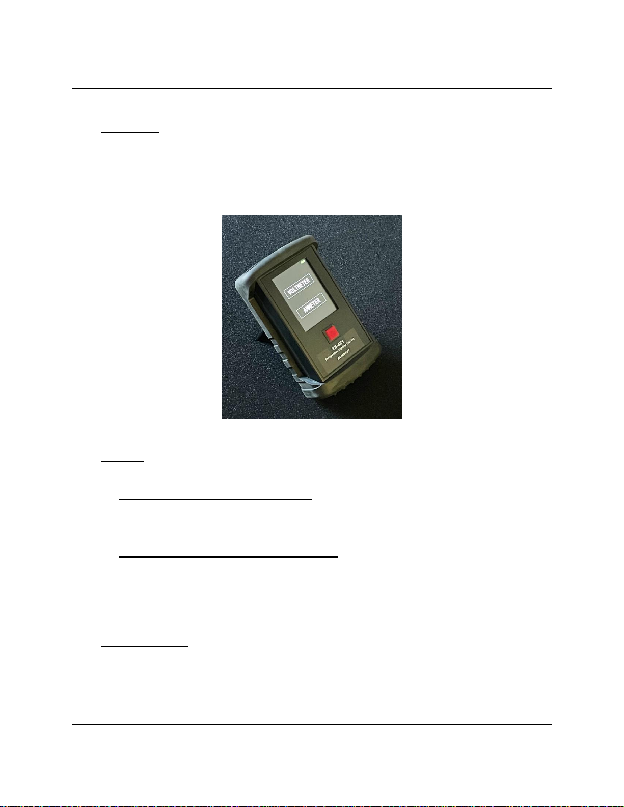
Model TS-421 Test Set
Page 7 of 725-60-45
6/19/23
4.0 Care & Maintenance
4.1 The TS-421 test set is a sensitive electronic instrument and should be handled with
appropriate care. Damage from obvious abuse cannot be covered by warranty.
•Be particularly careful to protect the touchscreen from any physical damage
(damage to the touchscreen is not covered by warranty).
•The enclosure is not completely sealed; keep the test set away from rain, spills,
and fluids to prevent damage to internal electronics.
•Do not apply external electrical inputs, except the AC charger provided.
•Protect from extreme temperatures and humidity; it is best to store the instrument
in temperature-controlled spaces.
•It is recommended to keep the protective cover in place at all times except for
battery replacement. (Note: the back of the protective cover is provided with a
rotating stand that can be removed if it is not useful.)
•Avoid excessive exposure to sunlight and UV radiation.
4.2 Maintenance is limited to wiping the unit enclosure and touchscreen down lightly with a
clean cloth moistened with alcohol. DO NOT use cleaners or solvents.
4.3 Field repairs except battery replacement are not authorized and will void warranty.
4.4 The P/N 6-1036 NiMH rechargeable battery is integral to the replaceable back panel of
the test set. The battery has a nominal 5 to 7 year life. Battery charge retention will
diminish over time and usage. The battery should be replaced when the charge retention
level becomes unacceptable. Battery replacement can be accomplished at any time
without affecting calibration. Replacement is accomplished as follows:
•Remove protective cover.
•Remove back panel/battery assembly of the test set; retain 4 attach screws.
•Disconnect the battery connection to the test set and discard the old back
panel/battery assembly.
•Connect new the battery connection on the replacement back panel/battery
assembly with same orientation.
•Secure new back panel/battery assembly with four attach screws.
5.0 Calibration
A separate BaseWest calibration manual, 25-60-46, is provided with each new unit, and is
available on the BaseWest website. Calibration is recommended at one-year cycles but is
dependent on user requirements and policy. Calibration can be accomplished without
opening the test set enclosure. See the calibration manual for recommended accessories.