manuals.online logo
Brands
  1. Home
  2. •
  3. Brands
  4. •
  5. Altek
  6. •
  7. Test Equipment
  8. •
  9. Altek 941 User manual

Altek 941 User manual

ALTEK
DATA SHEET
ALTEK INDUSTRIES CORP
GENERAL DESCRIPTION
941
MULTI-FREQUENCY CALIBRATOR
MODEL 941
Calibrate your turbine meters, frequency counters, vibration
systems, tachometers, vortex shedders, integrators and any
otherfrequencydevicesintheshop,plantorfield.Measurefrom
0.01Hzto250.00KHzwithresolutiondownto0.01Hz.Foryour
slowersignalssourceormeasurefrom4.0to2000.0Countsper
Minute (CPM) or from 10 to 20000 Counts per Hour (CPH).
Quickly indicate process signals...no more waiting around with
stopwatch and calculator.
“SOURCE MODE” FUNCTION GENERATOR
Select sine wave outputs to simulate vibration pickups and
variablespeeddrives andsquarewavesto simulateflowmeters
and magnetic pickups. Any frequency from 0.01 Hz to 250.00
KHz can be sourced in four frequency ranges to calibrate
tachometers, counters, data loggers, turbine meters and
frequency transmitters. For low frequency applications such as
positive displacement flowmeters, Watt-hour meters, slow rate
integrators and assembly line counting, the Model 941 sources
signals as low as 1 CPH (0.0002777 Hz). Amplitude is adjust-
able from 50 millivolts to 12 Volts peak-to-peak.
Three “QUIK-CHEK” output values are remembered for each
range. Turn the knob to check trip points, controller action and
to control variable speed drives. The fast response 941 sets
quickly without overshoot but allows slow changes at your own
rate.Memoryis retained for eachrangeevenwhenpower is off.
“READ MODE" MEASURES WIDE RANGE
OF FREQUENCIES AND WAVEFORMS
Use out in the field to check the signals from your flowmeter
pickups, velocity and motion detectors, Frequencies can be
directlymeasuredfrom 0.01Hzto250.00 KHz infourfrequency
ranges.
Measure extremely slow frequencies (<1 Hz) with high reso-
lution using CPM & CPH. Instead of displaying 1/2 Hz as 0.5
Hz(1 digit of resolution) as with most with frequency counters
youcandisplayitas30.0CPM(3digitsofresolution)oras1800
CPH (4 digits of resolution). You can now measure these slow
signals in seconds with the Model 941 instead of the minutes
needed with a totalizer, stopwatch and calculator. Signals
from 30 mV to 240 V peak-to-peak with a minimum pulse width
of 2 microseconds can be measured.
Useformonthswithoutreplacingthebatteries.Six“AA”alkaline
batteries provide more than 40 hours of continuous output or
more than 80 hours of continuous frequency measurement. An
optional AC adaptor can be used when the battery is low or for
continuous bench and field use.
• 0.001% ACCURACY
Locked to high stability crystal
• SIX REAL-WORLD RANGES
1 to 20000 Counts-per-Hour
0.1 to 2000.0 Counts-per-Minute
0.01 t0 999.9 Hertz
0.1 to 9999.9 Hertz
0.001 to 99.999 kilohertz
0.01 to 250.00 kilohertz
• "QUIK-CHEK® SWITCH
Store 18 values for instant recall
Three memories for each range
• THREE OUTPUT WAVEFORMS
Sine Waves, Zero Crossing
Square Waves, Zero Based
Square Waves, Zero Crossing
• SIMULATE & MEASURE DRY CONTACTS
Add module for relay contacts
OPERATING INSTRUCTIONS
GENERAL
TURN-ON
Each time the Model 941 is turned on, the
LCD will display all segments for about 1
second. It then displays the currently
selected waveform (Source Mode) for
approximately 3 seconds.
1) Move the power switch to SOURCE or
READ. All segments on the LCD are
turned on during self test.
2) (SOURCE MODE ONLY) The display will
indicate the selected waveform for 3
seconds. Repeatedly press or press and
hold the SCROLL/STORE pushbutton to
change to the desired waveform.
3) (SOURCEMODEONLY)ThethreeQUIK-
CHEK frequencyoutputswillbethesame
as previously stored. Each time a
different range is selected, the three
QUIK-CHEK outputs for that range will
be recalled.
4) Move the mode switch to RANGE and
repeatedly press or press and hold the
SCROLL pushbutton to change to the
desired frequency range.
5) Return the mode switch to FREQ/TRIG
to source or read frequency signals.
CONNECTIONS
The Model 941 has built-in test leads with
alligator clips for attachment to instruments
or sensors with terminal blocks or flying
leads. An optional BNC connector attaches
to instruments or sensors equipped with
BNC’s for fast connections.
SOURCE MODE
Some receivers can only detect signals that go from positive to negative
(SineWaveorZeroCrossingSquareWaves)whileotherreceiversrequire
onlypositivesignals(ZeroBasedSquareWaves).TheModel941provides
a choice of these outputs.
OPERATING HINTS
ALTEK INDUSTRIES CORP
CHANGING BATTERY
Low battery is indicated by BAT on the LCD
Display. Approximately 10 Hours of opera-
tion remain before the LCD goes blank and
the Model 941 shuts itself down. Turn the
941 off, loosen the three captive screws
securing the battery compartment cover.
The six “AA” batteries are easily removed
and replaced. Replace the battery
compartmentcover, tighten the screwsand
turn on when ready to use.
RESET
The Model 941 may be reset to the factory
default setting. This will reset all the
“QUIK-CHEK” memories to display 1000
and will set the output and trigger levels to
1 V p-p.
1) Press and hold the SCROLL/RESET
pushbutton while turning the Model 941 on to
SOURCE or READ
2) Keep pressing the STORE pushbutton
for 10 seconds
3) All segments on the LCD will remain
displayed until the Model 941 has been
reset
FIELD & BENCH USE
The Model 941 comes with a carrying case
and a built-in tilt stand/hanger. The 941 is
held securely in the case by Velcro®even
with the carrying case open. The carrying
case also has a snap-on belt loop which can
also be looped around a pipe or rail.
The tilt stand is easily raised by pulling the
stand until it locks into place. The stand can
also be reversed for use as a hanger to
suspend the Model 941.
›12
10.0
6.0
3.0
1.0
0.6
0.3
0.1
.06
.03
x10 SOURCE
8.8.8.8.8
OVER
MAX
HI
LO
MIN
UNDER
GATE
READ BAT
MHz
kHz
CPM
CPH
SEC
%
TOTAL
CUSTOM
S
C
R
O
L
L
S
T
O
R
E
R
E
S
E
T
ROCHESTER NY 14623
ALTEK MODEL 941
10.0
6.0
3.0
1.0
0.6
0.3
0.1
.06
.03
x1 SOURCE
109.41
kHz
FREQUENCY CALIBRATOR
SOURCE READ
OFF
LEVEL
FREQ
RANGE
X1/X10
TRIG
RANGE
HI
SET
LO
MAX
READ
MIN
S
C
R
O
L
L
S
T
O
R
E
R
E
S
E
T
9VDC
SYMPTOM CHECK SOLUTION
Lack of
Response
Wrong Range
Lack of
response or
jittery signal
Makesureallpowerandsignals
are properly connected.
Turn Model 941 OFF and back
on to SOURCE. Repeatedly
press the SCROLL/STORE
pushbutton until the correct
waveform is displayed.
Move the mode switch to
RANGEandpresstheSCROLL/
RESETpushbuttonuntilthecor-
rect range appears in the LCD.
MovethemodeswitchtoLEVEL
and turn the knob while observ-
ing the logaristhimic bar graph
to match the input level of the
device being calibrated. Return
the mode switch to FREQ.
Connections
Waveform
Range
Peak Voltage
READ MODE
In order for the Model 941 to obtain the most accurate readings you
mustcorrectlysettheATTENUATOR,TRIGGERLEVELandRANGE.
Signals from 50mV to over 240 Volts p-p, with or without DC offsets
can be displayed.
SYMPTOM CHECK SOLUTION
GATE on LCD,
Displayshows0.0
OVER/UNDER
Range on LCD
Unstable reading
Make sure all power and sig-
nals are properly connected.
Setatx1forsignalsfrom50mVto
12 Volts p-p, x10 for signals over
12 V p-p.
Turn knob until GATE pulses
and readings are displayed.
Smallsignals withlarge DCoff-
sets may require a series ca-
pacitor.
Move the mode switch to
RANGE and press the
SCROLL/RESET pushbutton
until the correct range appears
in the LCD.
Turn knob until GATE pulses
and readings are displayed.
Connections
Attenuator
Input level
DC Offset
Range
Trigger Level
CPM/CPH CONVERSIONS
To Convert From: To: Divide By:
CPM Hz 60
CPH Hz 3600
To Convert From: To: Multiply By:
Hz CPM 60
Hz CPH 3600
OUT OF RANGE SIGNALS
Frequencies above or below those available
for the currently selected range will be
indicated by OVER and UNDER on the
display (See OPERATING HINTS).
OPERATING INSTRUCTIONS
FREQUENCY OUTPUT (SOURCE MODE)
SOURCE
1) Move the POWER switch to SOURCE
2) Move the mode switch to RANGE and
repeatedly press or press and hold the
SCROLL/STORE pushbutton to change
tothedesiredfrequencyrange.Returnthe
mode switch to FREQ.
3) Move the mode switch to LEVEL (AMPLI-
TUDE) and turn the Digipot (Knob) until
the logrithmic bargraph on the display
reachesthedesiredlevel.Returnthemode
switch to FREQ.
4) Connect the Model 941 to the input termi-
nals of the instrument or meter to be
calibrated
5) Adjust the digital pot to the desired output
value or QUIK-CHEK with previously
stored frequency outputs (see below)
Whenever SOURCE mode is selected the
word SOURCE will appear on the LCD
display. Tochange theoutputvalue,turnthe
speed sensitive digital pot. Turning the pot
slowly will cause a gradual change in the
output. A faster change will occur when the
pot is turned faster. This function operates in
all three output positions (HI, SET & LO).
STORE
1) Switch to HI or LO
2) Turn the digital pot to desired value
3) Press the STORE/SCROLL pushbutton
The LCD will flash once to show that the
value was saved
If a value is in the SET position and you want
that value stored in HI or LO, press and hold
the STORE/SCROLL pushbutton while
movingtheswitchtoHIorLO.Thedisplaywill
flash once to indicate the value has been
stored. Then release the STORE/SCROLL
button.
Hint: Pressing the STORE/SCROLL pushbutton will disable the
Model 941's frequency generator. Releasing the pushbutton will
re-enabletheoutput.Thisisusefulforsynchronizingwithdisplaysfor
slow (< 1 Hz) signals.
ALTEK INDUSTRIES CORP
FREQUENCY COUNTER (READ MODE)
READ
1) Move the POWER switch to READ
2) Move the mode switch to RANGE and
repeatedly press or press and hold the
SCROLL/RESET pushbutton to change
tothedesiredfrequencyrange.Returnthe
mode switch to TRIG.
3) Switch the MODE switch to LEVEL
(AMPLITUDE)totogglebetweenx1&x10
attenuation (Use x1 for signals from 30
mV to 12 V p-p, x10 for signals from 12 V
to 240V p-p). Return the mode switch to
TRIG.
4) ConnecttheModel941totheoutputofthe
instrument or sensor to be measured.
5) Adjust the trigger level to obtain a stable
frequency reading by turning the Digipot
(knob). A bargraph on the display will
show the approximate trigger level.
6) Use the “QUIK-CHEK” switch to display
present reading, MAXimum or MINimum
frequency.
The word GATE will appear on the display
whenever the Model 941 is measuring the
frequency signal and will flash each time the
displayed reading is updated.
MIN/MAX
To read the Maximum or Minimum frequen-
cies since READ mode was entered, simply
switch to MAX or MIN. The value will appear
on the LCD along with the word MAX or MIN.
The MAX/MIN values are automatically
updated and may be viewed at any time
without disturbing the other values. Pressing
the RESET/SCROLL pushbutton will cause
the 941 to stop counting frequencies and will
display zeros. Upon releasing the RESET/
SCROLL the Model 941 will display GATE,
resumecountingfrequenciesandupdate the
MAX & MIN values as the measured
frequency changes.
CPM
CPH
PERIOD READINGS
Select Counts-per-Minute (CPM) or Counts-
per-Hour (CPH) to measure slow frequency
signals. Frequencies as low as 0.1 CPM
(0.001666 Hz) and 10 CPH (0.002777 Hz)
canbemeasured(SeeCPM/CPHCONVER-
SIONS for conversion factors).
TRIGGER LEVEL
The adjustable TRIGGER LEVEL is used in
measurements of noisy signals, AC signals
superimposed on DC levels and to select
Voltage threshold for all other signals.
The bargraph on the display shows the
approximatelevelfrom0toover12Vpositive
peak with the attenuator set at x1. This
bargraph should be read as 0 to over 120 V
positive peak with the attenuator set at x10.
Forquickestreadings, determineorestimate
thevoltageleveltobe detected and set the
ATTENUATOR and TRIGGER LEVEL to
match.
OVER
UNDER
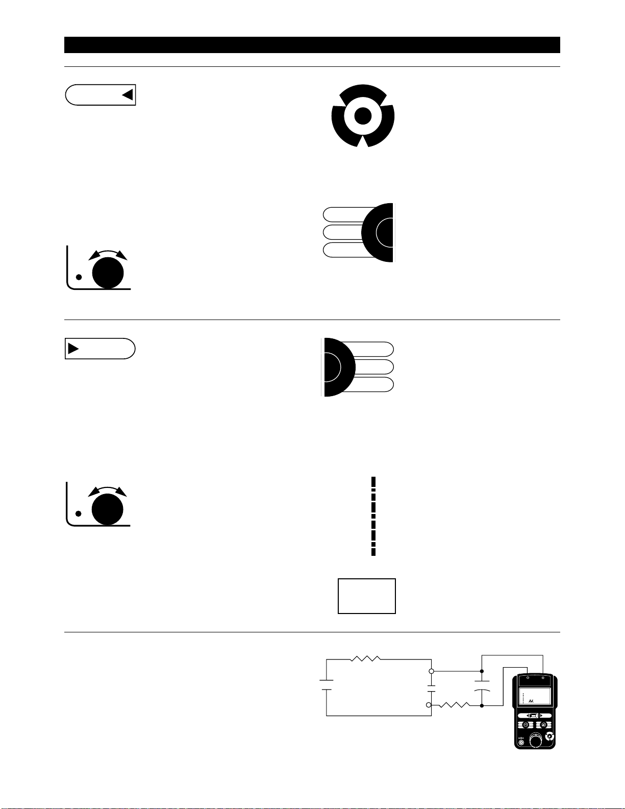
Isolated dry contact, open collector transis-
tor or opto-isolated frequencies may be
measured with the Model 941 with the
optional DRY CONTACT MODULE (Model
C-41) or with the circuit shown. In order
todetectcontactopeningorclosing,anexter-
nal battery or power supply, in series with a
5000 Ohm resistor, may be used. Select
connection polarity to provide desired signal
upon contact transfer. Relay or switch
contacts may require a resistor-capacitor
filter in order to eliminate contact bounce
errors. Typical filter values for mechanical
contactsare10KOhmsand0.1microfarads.
READING DRY CONTACTS
QUIK-CHEK
Any time you need a stored value just throw
the QUIK-CHEK switch. Any value in the
frequency range may be stored in HI & LO.
The Model 941 remembers the HI, LO and
SET values for all ranges (18 memories) for
you with the power on or off. Each time a
differentfrequencyrangeisselected,thelast
threeQUIK-CHEK valuesforthattypewillbe
recalled.
SOURCE
S
C
R
O
L
L
S
T
O
R
E
R
E
S
E
T
HI
SET
LOW
MAX
READ
MIN
ROCHESTER NY 14623
ALTEK MODEL 941
10.0
6.0
3.0
1.0
0.6
0.3
0.1
.06
.03
x1 SOURCE
485.3
CPM
FREQUENCY CALIBRATOR
SOURCE READ
OFF
LEVEL
FREQ
RANGE
X1/X10
TRIG
RANGE
HI
SET
LO
MAX
READ
MIN
S
C
R
O
L
L
S
T
O
R
E
R
E
S
E
T
9VDC
5000 Ohm
DRY
CONTACT
1 to 24 VDC 10 K
0.1
READ
›12
10.0
6.0
3.0
1.0
0.6
0.3
0.1
.06
.03
x10
O
M
H
L
O
M
U
G
SPECIFICATIONS
Variable Speed Drives
Telemetry Systems
Event Recorders
Vibration Monitors
Totalizers
Data Loggers
Velocity Detectors
Magnetic Pickups
DC Contact Closures
Turbine Flowmeters
Vortex Shedders
Positive Displacement Flowmeters
Watt-Hour Meters
V to F and F to V Converters
Integrators
Tachometers
Uninterruptable Power Supplies
Counters
Frequency Transmitters
TYPICAL APPLICATIONS
(Unless otherwise indicated, specifications are in ±% of Reading @ 23°C)
TYPICAL INDUSTRIES
Chemical Plants
Petroleum Refineries
Food Processing
Pipelines
Utilities
Water & Waste Treatment
Public Works
Steel Mills
Paper Mills
Textile Mills
Automotive Plants
Aerospace
Pharmaceutical
Glass & Ceramics
Metrology
Beverages
Plastics
Machinery
Ordinance
Computers
THREE YEAR WARRANTY
Our equipment is guaranteed against defective material and work-
manship(excluding batteries) for aperiod of three yearsfrom date of
shipment. Claims under guarantee can be made by returning the
equipment prepaid to our factory. The equipment will be replaced,
repaired or adjusted at our option. The liability of Altek is restricted to
that given under our guarantee. No responsibility is accepted for
damage, loss or other expense incurred through sale or use of our
equipment. Under no condition shall Altek be liable for any special,
incidental or consequential damage.
ORDERING INFORMATION Part No.
MODEL 941 FREQUENCY CALIBRATOR 941
WITH OPTIONAL BNC CONNECTOR 941-BNC
Included with each Model 941 are:
Carrying Case (Part No. 09-3784)
NIST Traceable Certificate and Three Year Warranty
OPTIONAL ACCESSORIES Part No.
AC ADAPTOR: 120 VAC, 50/60 Hz 9V-0120
AC ADAPTOR: 240 VAC, 50/60 Hz 9V-0240
DRY CONTACT MODULE C-41
AVAILABLE FROM:
© May 1996 Altek Industries Corp
RANGES
RANGE SOURCE READ GATE TIME
KHz 0.01 TO 250.00 0.01 TO 250.00 0.2 seconds
KHz 0.001 TO 99.999 0.001 TO 99.999 1 second
Hz 0.1 TO 9999.9 0.1 TO 9999.9 1 period
Hz 0.01 TO 999.99 0.01 TO 999.99 1 period
CPM 0.1 TO 2000.0 0.1 TO 2000.0 1 period
CPH 1 TO 20000 10 TO 20000 1 period
GENERAL
FREQUENCY STABILITY: <10 PPM/Year drift
TEMPERATURE EFFECT: ±0.001%/°C based on 23°C±23°C
BATTERIES:Six“AA”batteries(Alkalinesuppliedandrecommended)
BATTERY LIFE:
READ MODE: Nominal >80 hours
SOURCE MODE:
Nominal >50 hours at 250 KHz at 12V p-p
LOW BATTERY: “BAT” indication on the display at6.5 V nominal,
approximate10hoursleft.Batteriesshouldberemovedwhenstoring
unit >3 months.
ATTENUATOR: Logarithmic for smooth input/output signal level
control
OPERATINGTEMPERATURE RANGE:-5 to+140°F(-20to+60°C)
STORAGE TEMPERATURE RANGE: -13 to +149°F (-25 to +65°C)
RELATIVE HUMIDITY: 10 to 90%, non-condensing for 24 hours
WARM UP TIME: 5 seconds to rated accuracy
OVERALL SIZE: 73/16 x 4 x 27/16 inches (183 x 102 x 62 mm)
WEIGHT: 1lb, 7oz (0.650 kg)
READ MODE
ACCURACY: ±(0.001% of reading + 1 LSD)
SENSITIVITY: Triggers on positive peaks down to 40 mV peak, DC
coupled
MAXIMUM USABLE INPUT VOLTAGE: 240 VAC
MINIMUM PULSE WIDTH: 2 microseconds
INPUT IMPEDANCE: > 1 Meg Ohm + 60pF
TRIGGER LEVEL ADJUSTMENT: x1 & x10 Attenuator plus logarithmic
control
NOTE: High signal noise and low slew rate (Volts-per-second) may affect
reading uncertainty SOURCE MODE
ACCURACY: ±0.001% of reading
OUTPUT WAVEFORMS: Sine, Zero Based Square, and Zero
Centered Square Waves
OUTPUT AMPLITUDE: 50 mV to 12 V p-p, 50% ±1% duty cycle
RISETIME: <1microsecond @ 12V peak-to-peak
OUTPUT IMPEDANCE: 600 Ohms
SOURCE CURRENT: 8 mA maximum
SHORT CIRCUIT DURATION: Infinite
VOLTAGE PROTECTION: Protected against misconnection to 240
Volts AC/DC without fuses for 30 seconds
Specifications subject to change without notice
OTHER PRODUCTS
Altek designs and manufactures fast, accurate instruments for mea-
surement, generation and simulation of virtually every process control
signal. Consult our factory directly or contact your local stocking
representative to order precise, low cost Milliamp Calibrators, Voltage
Sources, Direct Thermocouple Sources, RTD Simulators and Fre-
quency Sources. Altek also produces calibrators for custom ranges
and unique applications. Additional models and ranges are frequently
added to the Altek instrument family to meet all of your critical
calibration requirements. Altek products are made in the USA.

Other Altek Test Equipment manuals

Altek 942 User manual

Altek

Altek 942 User manual

Altek Pocketcal 134-2 User manual

Altek

Altek Pocketcal 134-2 User manual

Altek a 830-KP User manual

Altek

Altek a 830-KP User manual

Altek 211 User manual

Altek

Altek 211 User manual

Altek 334A User manual

Altek

Altek 334A User manual

Altek 222A User manual

Altek

Altek 222A User manual

Altek 311 User manual

Altek

Altek 311 User manual

Popular Test Equipment manuals by other brands

OYPLA DIY 4580 user manual

OYPLA DIY

OYPLA DIY 4580 user manual

Extech Instruments CB10 user guide

Extech Instruments

Extech Instruments CB10 user guide

SecuControl ITS 4600 Series Reference handbook

SecuControl

SecuControl ITS 4600 Series Reference handbook

Fluke 975 AirMeter Application note

Fluke

Fluke 975 AirMeter Application note

Matrix 620B user manual

Matrix

Matrix 620B user manual

Fluke 165X Quick reference guide

Fluke

Fluke 165X Quick reference guide

Hioki BT3564 instruction manual

Hioki

Hioki BT3564 instruction manual

SIGLENT TECHNOLOGIES SHS800 Series QS03008-E01 quick start

SIGLENT TECHNOLOGIES

SIGLENT TECHNOLOGIES SHS800 Series QS03008-E01 quick start

PMK KSZ 10B instruction manual

PMK

PMK KSZ 10B instruction manual

Bayrol Pooltester pH-O2 instruction manual

Bayrol

Bayrol Pooltester pH-O2 instruction manual

Monacor HYB-800 TEST Brief instructions

Monacor

Monacor HYB-800 TEST Brief instructions

Schumacher schulink SBT1 owner's manual

Schumacher

Schumacher schulink SBT1 owner's manual

GE Druck ADTS 2 Series Calibration manual

GE

GE Druck ADTS 2 Series Calibration manual

Centroid DP-7 Operator's manual

Centroid

Centroid DP-7 Operator's manual

Keysight 16048D Operation and service manual

Keysight

Keysight 16048D Operation and service manual

Rigol DS1000Z Series user guide

Rigol

Rigol DS1000Z Series user guide

Rigol MSO4000 Series quick guide

Rigol

Rigol MSO4000 Series quick guide

Axcom SMAPL4P operating instructions

Axcom

Axcom SMAPL4P operating instructions

manuals.online logo
manuals.online logoBrands
  • About & Mission
  • Contact us
  • Privacy Policy
  • Terms and Conditions

Copyright 2025 Manuals.Online. All Rights Reserved.