GDD Instrumentation TDLV User manual

SAMPLE CORE
IP TESTER
Model TDLV
Instruction Manual
860 boul. de la Chaudière, suite 200
Québec (QC), Canada, G1X 4B7
Tel.: +1 (418) 877-4249
Fax: +1 (418) 877-4054
E-Mail: [email protected]
Web site: www.gdd.ca

Instrumentation GDD Inc. 2018-09-18 Page 2
1 Introduction ................................................................................................................ 3
2 SCIP tester accessories................................................................................................. 4
3 SCIP tester components ............................................................................................... 5
4 Power ......................................................................................................................... 6
5 Important tips for getting good results ........................................................................ 7
6 Quick Start Guide ........................................................................................................ 9
7 How to use Core Holders ........................................................................................... 18
7.1 Core Holders - components ......................................................................................... 18
7.2 How to use it .............................................................................................................. 24
8 Tools menu ............................................................................................................... 29
8.1 Config Option.......................................................................................................... 30
8.2 Special options ........................................................................................................ 36
8.3 Show Options.......................................................................................................... 41
8.4 Memory Option ...................................................................................................... 45
9 Transferring data ...................................................................................................... 49
9.1 ActiveSync Installation and settings ........................................................................ 49
9.2 Windows Mobile Device Center installation and settings ...... Erreur ! Signet non défini.
9.3 Connecting the Archer2 with a desktop PC ........................... Erreur ! Signet non défini.
9.4 Transferring files(s) from the Archer2 PDA to a desktop PC ... Erreur ! Signet non défini.
9.5 Convert the Archer2 as a USB port ........................................ Erreur ! Signet non défini.
10 GDD SCIP software update ........................................................................................ 58
11 Troubleshooting ........................................................................................................ 61
11.1 Problems .................................................................................................................. 61
11.2 Bluetooth Partnership .............................................................................................. 65
12 Technical help ........................................................................................................... 69
Annex 1 – Example of Generic Data File ............................................................................. 70
Annex 2 – Example of a resistivity/chargeability profile using SCIP Tester data .................. 71
Annex 3 – Using SCIP Tester with a borehole probe ............................................................ 72
Table of contents

Instrumentation GDD Inc. 2018-09-18 Page 3
1 Introduction
The SCIP (Sample Core I.P.) tester is an efficient, compact, lightweight and low consumption unit
designed for resistivity measurements.
The SCIP tester uses a field handheld computer to process data acquisition. The operating system
is Windows Embedded Handheld 6.5 Professional.
Characteristics:
Related to the GDD Rx 8-32: The SCIP acts as a 1 dipole receiver relating DDH Cores to the
resistivity and IP surveys.
Programmable windows: The SCIP offers twenty fully programmable windows for higher
flexibility in defining the IP decay curve.
Available Modes: Arithmetic, logarithmic, semi-logarithmic, Cole-Cole and user defined.
IP display: Chargeability values, Resistivity and IP decay curves are displayed in real time on
a PDA.
Internal memory: Over 100 000 readings can be stored in the PDA's internal memory. Each
reading includes the full set of measurement parameters. Data are stored on flash type
memory and cannot be lost even if the PDAs battery is totally discharged or absent.
Transmitting mode: Can be used as a low voltage transmitter of 3, 6, 9 or 12V or 0.5, 5, 50 or
500uA.

Instrumentation GDD Inc. 2018-09-18 Page 4
2 SCIP tester accessories
A 1x SCIP tester model TDLV
B 1x Set of core holders
C 1x Archer
2
Field computer with one rechargeable 10600mAh Li-Ion battery, one hand
strap and one capacitive stylus
D 1x Set of red/black cables banana/banana or banana/alligator
E 1x SCIP tester AC charger with international plug kit (universal voltage)
F 1x Archer
2
AC charger with international plug kit (universal voltage)
G 1x Serial communication cable 9 pos. D-SUB female - 9 pos. D-SUB female
H 1x Archer
2
micro USB sync cable
I 1x Screwdriver (for Archer
2
battery cap)
J 1x Allen key
K 1x Handy pocket tape (10’/3m)
L 1x 70g bottle of Cupric Sulphate with MSDS
M 1x SCIP tester Instruction Manual and SCIP tester Utilities CD or USB Stick (contains SCIP
Tester software, Sync software, SCIP Tester manuals, Archer
2
manual)
N 1x Archer
2
Quick Start Guide
Optional accessories:
Borehole probe
(including probe, backpack reels and cable)
A
B
F
G
H
I
J
C
D
E
K
L
M
N

Instrumentation GDD Inc. 2018-09-18 Page 5
3 SCIP tester components
The SCIP tester components are described in this section.
A - RS-232 connector - 9 pin serial communication port
This connector is used to connect the RS-232 cable between the Archer
2
Field PDA and the
SCIP tester.
B - CABLE/WIRELESS switch
This switch is used to select CABLE (RS-232) or WIRELESS (Bluetooth) communications with
the PDA. The red light indicates the WIRELESS position.
C - ON/OFF switch
This switch is used to turn the SCIP tester ON. The red light indicates that the SCIP tester is
ON.
D - CHARGER connector
This connector is used to charge the SCIP tester's battery with the AC charger, and to supply
power to the SCIP tester when the battery is discharged.
E - TX terminals
Transmitting connectors.
F - RX terminals
Receiving connectors.
A
B
C
D
E F

Instrumentation GDD Inc. 2018-09-18 Page 6
GDD’s SCIP tester is powered by a rechargeable Li-Ion battery. Here are a few tips for using and
storing the SCIP tester.
Usage
Use the power supply provided by GDD to charge the SCIP tester battery. If you want to use
another AC charger, make sure that the specifications are the same as those of the AC
charger provided by GDD.
Do not replace the SCIP internal battery without the authorization and advice of GDD’s
technicians.
The total operating time of the SCIP tester depends on environmental conditions. Using the
SCIP in very cold weather (-200C to –400C) decreases the operating time. At normal
temperatures (20°C), the operating time is from 10 to 16 hours.
The power level of the batteries and the charging status appear on the main screen of the
Archer2 PDA when using the SCIP program.
Use the AC charger as a power supply for working with the SCIP tester when the battery
level is too low.
There is a protection circuit in the SCIP tester that prevents charging the battery in cold
weather (under 0°C) or in hot weather (over 45°C).
The SCIP will turn itself off when the battery reaches a critical low level.
Storage
When storing the SCIP tester for a few days or more, make sure that the battery is fully
charged.
Store the SCIP tester in a cool, dry place.
4 Power

Instrumentation GDD Inc. 2018-09-18 Page 7
5 Important tips for getting good results
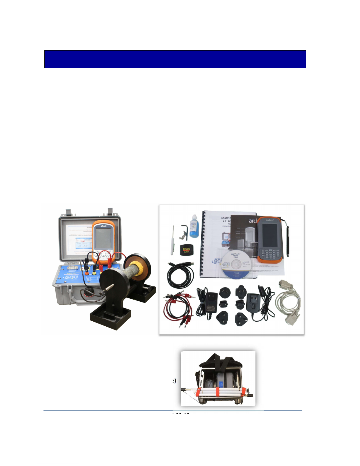
The SCIP (Sample Core Induced Polarization) measures geophysical properties of the ore such as
apparent resistivity and chargeability. The SCIP simulates an Induced Polarization survey. The
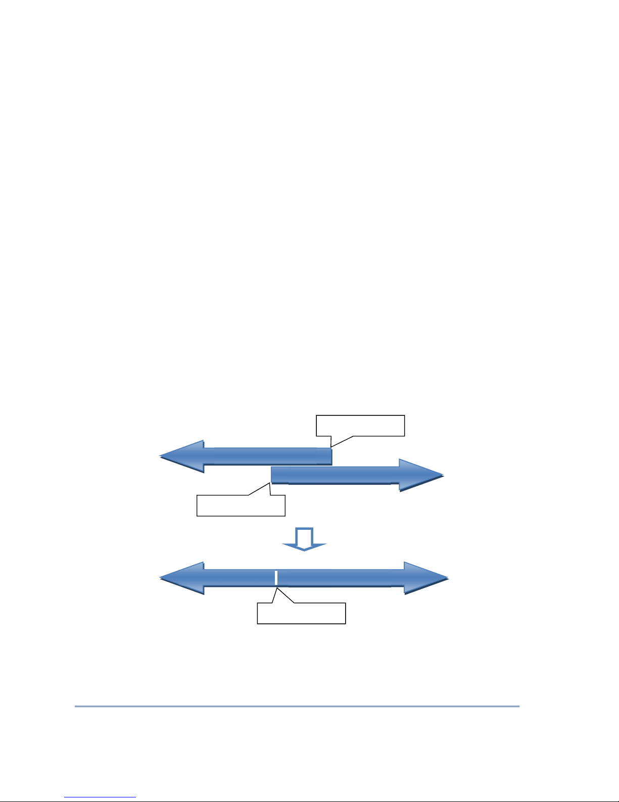
waveform is ON+, OFF, ON-, OFF. The current flows through the sample and is then switched off.
While the current is flowing through the sample, a resistivity (Rho) is calculated from the ON Time
Voltage. When the current is switched off, the voltage across the sample drops and a decay curve
is measured. The Chargeability (M) is calculated from this DECAY.
Here are a few tips about preparing and measuring your core samples:
Note: It is very important to always use the same methodology and keep the samples under
the same environmental conditions for all measurements of all samples in order to compare
them with each other.
Soak your core samples in water for a few days before testing them.
It is recommended to soak the samples in water in order to keep their properties as in
the natural environment. The best way to take measurements would be on fresh
samples. If it is not possible, two days of soaking should be sufficient. Note however
that it is not necessary to leave the samples to soak. The important point is to keep the
same measurement conditions for all samples. The values will not necessarily match
with field data but the measured values of a sample compared to another one allows
defining which ones are less resistive and/or more chargeable. You may then correlate
anomalies versus results from the field.
Note: The use of distilled water by osmosis could dilute the natural salts contained in
the samples and falsify the measurement results. In this case, the use of running
water seems an acceptable compromise.
Remove the excess of water on the core sample before beginning the measuring process.
Use a saturated copper sulphate solution.
To take a measurement, the sample is fixed between electrodes by using sponges
dipped in copper sulphate solution. Make sure that some copper sulphate crystals are
not dissolved in water to get a saturated solution.
Before starting the measurement, make sure that the core sample is completely dry on its
surface.
During the whole measuring process, make sure that the work bench, the core holders and
the rod that fix together the core holders are completely dry.

Instrumentation GDD Inc. 2018-09-18 Page 8
During the measuring process, wait until the contact resistance becomes stable before
taking a reading. This may take a few minutes.
Select the most appropriate settings.
Select the most appropriate stack in order to stop the reading when the chargeability
and the resistivity responses are stable. Depending on your sample and contact
resistance, the number of stacks needed to obtain stable values will vary.
We suggest using the same timing and windows than your field IP survey. Otherwise, a
timing of two (2) seconds and arithmetic windows give good results.
Use the appropriate mode (constant current or constant voltage).
There are two modes of measurement, voltage and current. In order to determine
which one to use, the contact resistance value (Rs) can be a good indication. For a Rs
between 1 kOhm and 24 kOhms both modes are possible. However, we suggest
selecting a constant current for an Rs lower than 1 kOhm and a constant voltage when
Rs is greater than 1 kOhm. In voltage mode make sure that the Vp (mV) is greater than
half of the selected voltage and in current mode make sure that the I (uA) is almost the
same value of the selected current. If there is saturation, the reading may not be
reliable. In that case, try a lower current or a lower voltage.
For better results, take the average of several readings on each core sample.
Constant current
Constant voltage
Rs = 24 kOhms
Rs =
1
kOhm
Rs =
1
kOhm
Constant current
Constant
voltage

Instrumentation GDD Inc. 2018-09-18 Page 9
6 Quick Start Guide
Important note: Using a finger may still be the preferred option for projected capacitive screen
technology, but we understand a stylus may also be necessary (like when it’s cold). The way you
hold a capacitive stylus really impacts how it works. To register a point, it is like the screen is taking
a sample from which to calculate the position. It then snaps to the closest line on a grid. If you
hold a capacitive stylus at an angle, it registers less area and does not calculate your true position
as well. For best results on a capacitive screen like the Archer2, hold the stylus as perpendicular to
the screen or straight up as you can. In this section, you will see some tips to use the Archer2
keypad to perform some actions of the SCIP program.
1. Place the core sample into the core holders (see Section 7 – How to use Core Holders).
2. Turn the SCIP tester ON using the ON/OFF switch on the front panel.
3. Select the communication mode using the CABLE/WIRELESS switch on the SCIP tester's front
panel. If Cable mode is selected, connect the serial communication cable between the SCIP
(RS-232 connector) and the Archer2 Field PDA.
4. Turn on the Archer2 Field PC with the ON/OFF key.

Instrumentation GDD Inc. 2018-09-18 Page 10
5. Click on GDD SCIP icon in the favorites bar.
6. Select the communication mode: RS-232 (CABLE) or BLUETOOTH (WIRELESS). You can move
back and forth between the different actions using the tab button ( ) of the keypad. Press
Enter button ( ) of the keypad to perform the highlighted action.
7. The following screen appears.
Make sure that the opened window is the SCIP_CORE window. See section 8.2 for more
details.
Title bar
Dashboard
Favorites
Tile Bar

Instrumentation GDD Inc. 2018-09-18 Page 11
8. Click START (or press , and on the keypad) to begin the acquisition process.
9. The following screen appears. The ‘Contact’ is the value of the core resistance.
If the value of the core resistance is higher than 50 000 kOhms (50 MOhms), the value of
the chargeability could be affected. If this should be the case, if you click on NEXT, the
following message should appear:
Click on Yes to continue or click on NO to stop the measuring process.

Instrumentation GDD Inc. 2018-09-18 Page 12
10. Click on NEXT (or press , and on the keypad) to continue.
11. Set the parameters of the core sample in the ‘Parameters’ window.
Open the soft keyboard at the bottom of the screen by clicking on it. You can also use the
numeric keypad of the Archer2 Field PC to enter numeric values. Use the tab button ( )
to advance the cursor to the next tab stop.
Project name Sample name
or number
Sample length
(l) mm
Core sample
diameter (D) mm Half sample :
D
l
Cross-sectional
area (S) mm2
Value of D in mm
or S in mm2

Instrumentation GDD Inc. 2018-09-18 Page 13
For a core sample, select Diameter and enter the diameter of the cross section in mm. If
you measure a half core sample, select Half Sample.
For any other type of sample, enter the cross-sectional area in mm2.
12. In the ‘Windows’ window, select the maximum number of stacks, the signal time and the
mode (windows time definition). See Section 8.1 for more details.
The time to get one reading increases with the number of stacks and the signal timing. It
could take up to three (3) hours to get one reading with 50 stacks at a timing of 128 seconds.
13. In the ‘TX’ window, select if you want to use a constant voltage or a constant current. You
can use a voltage of 3, 6, 9 or 12 volts or a current of 0.5, 5, 50 or 500 µAmps.

Instrumentation GDD Inc. 2018-09-18 Page 14
14. Click Ok (or press shift +5 OK on the keypad) to close the setting windows.
15. The following screen appears. See Annex 1 for details on the readings.
In constant current mode, if a little red square appears in the window that means that the
signal is saturated. Stop the measuring process, select a lower current and start the readings
over. These instructions appear in a pop-up window when you click on the red square.

Instrumentation GDD Inc. 2018-09-18 Page 15
16. To stop the readings and save the data, click on STOP, or wait until the SCIP has finished
acquiring data.
17. Click YES to confirm the operation.
18. Click YES to save readings to Memory.

Instrumentation GDD Inc. 2018-09-18 Page 16
The MEM: number increases by one after saving. You can save more than one reading
before creating a file.
19. Click on ‘Tools’ and select ‘Memory’ to create a file with your saved data (or press , and
on the keypad to open the Tools menu and press shift + or to highlight the
different options) . Click on ‘Save File’ (or press when Save File is highlighted).
20. When this screen appears, the GDD Generic file option will be selected by default (.gdd file).
The Geosoft option can be chosen to create a specific file to be imported in Geosoft
software. Take note that in the Geosoft file (.dat file), some information as core ID, length
and diameter is missing. The Fullwave option can be selected to create a file that contains
the full waveform sampled data.

Instrumentation GDD Inc. 2018-09-18 Page 17
21. Enter your File name and the location of your file in the Archer2 Field PC memory.
22. Click on Save to save your file.
23. In Bluetooth mode, always close the SCIP program before turning off the SCIP tester to
prevent that the Archer 2 freezes or stops responding (see Section 11 – Troubleshooting).

Instrumentation GDD Inc. 2018-09-18 Page 18
7 How to use Core Holders
7.1 Core Holders - components
1
5
2
3
4
6
7

Instrumentation GDD Inc. 2018-09-18 Page 19
1. Receptacle (2x)
The two receptacles must be used to keep the surface between the two core holders dry. The
receptacles keep all the liquid (water, copper sulphate) in them. It is possible to screw the
receptacles onto a table using the two base holes.
2. Holder (2x)
The two holders keep the core sample in place. Fix the holders to the receptacles with two bolts
using the Allen key provided with the Core Holder.

Instrumentation GDD Inc. 2018-09-18 Page 20
3. Electrode (2x)
The electrode consists of a copper disc with a stainless-steel bolt. The banana connector can be
inserted into the bolt for better contact. It is possible to adjust the distance between the
electrode and the holder by screwing or unscrewing the electrode using the Allen key.
Table of contents
Other GDD Instrumentation Test Equipment manuals