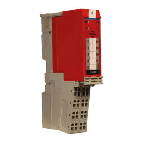
BASF EXACTUS IFX-21 User manual

IFX-21 USER GUIDE
INDUSTRIAL COMMUNICATIONS MODULE

IFX-21 User Guide
BASF Contact Information 7/12/2019 V004 2 of 22
1. CONTACT INFORMATION
TECHNICAL
4011 SE International Way, Suite 604
Portland, OR 97222
Phone: (503) 794-4073
Fax: (503) 794-5591
PURCHASING
46820 Fremont Blvd.
Fremont, CA 94538
Phone: (510) 490-2150
Fax: (510) 252-1871
Copyright© 2019 BASF Corporation. All rights reserved.
EXACTUS® and TemperaSure are registered trademarks of BASF Corporation. The data contained in this publication are
based on our current knowledge and experience. In view of the many factors that may affect processing and application of
our product, these data do not relieve processors from carrying out their own investigations and tests; neither do these
data imply any guarantee of certain properties, nor the suitability of the product for a specific purpose. Any descriptions,
drawings, photographs, data, proportions, weights, etc. given herein may change without prior information and do not
constitute the agreed contractual quality of the product. It is the responsibility of the recipient of our products to ensure
that any proprietary rights and existing laws and legislation are observed.
Although all statements and information in this publication are believed to be accurate and reliable, they are presented
gratis and for guidance only, and risks and liability for results obtained by use of the products or application of the
suggestions described are assumed by the user. NO WARRANTIES OF ANY KIND, EITHER EXPRESS OR IMPLIED,
INCLUDING WARRANTIES OF MERCHANTABILITY OR FITNESS FOR A PARTICULAR PURPOSE, ARE MADE
REGARDING PRODUCTS DESCRIBED OR DESIGNS, DATA OR INFORMATION SET FORTH. Statements or
suggestions concerning possible use of the products are made without representation or warranty that any such use is
free of patent infringement and are not recommendations to infringe any patent. The user should not assume that toxicity
data and safety measures are indicated or that other measures may not be required. ©2019 BASF Corporation.

IFX-21 User Guide
BASF Contents 7/12/2019 V004 3 of 22
2. CONTENTS
1. Contact Information ................................................................................................................................ 2
2. Contents ................................................................................................................................................... 3
3. Product Overview .................................................................................................................................... 4
Description and Intended Use ................................................................................................................ 4
Certifications and Approvals .................................................................................................................. 4
Identification ........................................................................................................................................... 4
Device Overview .................................................................................................................................... 4
4. Installation and Commission ................................................................................................................. 5
Software Minimum Requirements .......................................................................................................... 5
Transportation and Storage ................................................................................................................... 5
Mounting ................................................................................................................................................ 6
Device Wiring ......................................................................................................................................... 7
5. Device Operation and Setup ................................................................................................................ 10
Overview of Connection Methods ........................................................................................................ 10
Value Display and Indicating LEDs ...................................................................................................... 11
Device Configuration ............................................................................................................................ 12
The Configuration Menu ...................................................................................................................... 13
Analog Output Operation ..................................................................................................................... 14
Analog Output Configuration ................................................................................................................ 14
6. Maintenance .......................................................................................................................................... 14
7. Specifications ........................................................................................................................................ 15
General ................................................................................................................................................ 15
Technical .............................................................................................................................................. 15
8. Warnings ................................................................................................................................................ 18
9. Troubleshooting .................................................................................................................................... 18
Troubleshooting Instructions ................................................................................................................ 18
Repair, Service, and Returns ............................................................................................................... 19
Disposal ............................................................................................................................................... 19
10. Appendix .............................................................................................................................................. 20
7-Segment Display ............................................................................................................................. 20
MODBUS/TCP ................................................................................................................................... 21
MODBUS/RTU (RS485) Implementation ........................................................................................... 2 1
MODBUS register map ...................................................................................................................... 22

IFX-21 User Guide
BASF Product Overview 7/12/2019 V004 4 of 22
3. PRODUCT OVERVIEW
D
ESCRIPTION AND
I
NTENDED
U
SE
The IFX-21 is a smart device for re-transmission, monitoring, and break out of EXACTUS
®
pyrometer communications in industrial environments. It continuously buffers pyrometer output
and makes the readings available to various isolated ports and protocols, including a user
defined passive 4-20mA analog signal.
C
ERTIFICATIONS AND
A
PPROVALS
I
DENTIFICATION
The IFX-21 features a Nameplate as seen in Figure 1.
F
IGURE
1:
E
XAMPLE NAMEPLATE
1. Manufacturer and Product ID
2. Order Code and Serial Number
3. Power supply and current consumption
4. Ambient temperature range
5. Device MAC address
6. Device and Firmware version
7. Approval Logo
D
EVICE
O
VERVIEW
The IFX-21 is a DIN rail mountable plastic enclosure with a number of ports on its top, bottom,
and front. The top has two sets of 4 spring terminals and one RJ45 port. The bottom has one
set of 4 spring terminals and two RJ45 ports. The front has a clear polycarbonate door which
covers a 5 character display, 2 indicating LED’s, and a USB service port.

IFX-21 User Guide
BASF Installation and Commission 7/12/2019 V004 5 of 22
3.4.1. P
ORT
C
ALLOUT
F
IGURE
2:
D
EVICE OVERVIEW
1. Analog outputs
2. Device power input
3. Pyrometer port
4. 5 Character display
5. USB mini-B PC service port
6. Power and Error indication LEDs
7. TIA 485-A (RS485) port
8. Ethernet TCP/IP 2 port switch
Refer to section 7.2 for additional technical information about these ports.
4. I
NSTALLATION AND COMMISSION
S
OFTWARE
M
INIMUM
R
EQUIREMENTS
Windows 7, 8.1, and 10 compatible.
Windows 10 only for USB service port connection
TemperaSure Version: 5.7.0.0 or later
Pyrometer Models EX#-100 Firmware: 3.0.1.3 or later
Pyrometer Models EX#-#10 Firmware: 9.3.0.0 or later
T
RANSPORTATION AND
S
TORAGE
The device should be transported and stored such that it is protected from impact, condensing
atmospheres, and influx of liquids or contaminants.
Permitted storage temperature range: -40 to 85°C (-40 to +185°F)

IFX-21 User Guide
BASF Installation and Commission 7/12/2019 V004 6 of 22
M
OUNTING
The IFX-21 is intended to mount on a 35mm top hat style DIN rail (IEC 60715 TH35). To
ensure optimal performance the IFX-21 should be mounted on a grounded rail inside an
enclosure with the appropriate NEMA rating for the environment. Where appropriate cooling
air and/or radiation shielding should be installed to ensure ambient temperatures remain within
device operational limits (see Section 7.1).
In choosing a mounting location note should be taken that the device power, analog output,
and pyrometer ports are located on the top of the device while communications, both Ethernet
and Modbus, are on the bottom.
4.3.1. D
IMENSIONS
F
IGURE
3:
D
EVICE
D
IMENSIONS
4.3.2. I
NSTALLATION PROCEDURE
F
IGURE
4:
I
NSTALLATION STEPS
1. Pull down on spring clip
2. Hook top DIN rail forks over 35mm DIN rail
3. Release spring clip

IFX-21 User Guide
BASF Installation and Commission 7/12/2019 V004 7 of 22
D
EVICE
W
IRING
4.4.1. W
IRE
G
AUGE
BASF recommends wire gauges of not less than 18AWG and no more than 12AWG. For
best results stranded wire should be tinned or crimped into an appropriately sized ferrule.
Ethernet connections may utilize either CAT5 or CAT5e cables, CAT5e is preferred
where available.
4.4.2. T
ERMINAL BLOCKS
The power, analog output, and Modbus terminals use detachable spring-cage connector
blocks. To insert or release a wire, push in the tab as shown in Figure 5. Pin out
numbering listed below for all terminal blocks, see section 7.2 for related input/outputs.
F
IGURE
5:
W
IRE RELEASE TAB
In some situations, it may be necessary to remove the entire plug assembly. This can be
done by pulling the connector down and away from the device. If a tool is used care must
be taken not to crush or pierce the plastic.
F
IGURE
6:
T
ERMINAL BLOCK REMOVAL

IFX-21 User Guide
BASF Installation and Commission 7/12/2019 V004 8 of 22
4.4.3. W
IRING DIAGRAMS
The IFX-21 enclosure features a simplified wiring diagram for all permanent device
connections.
F
IGURE
7:
D
EVICE WIRING
Additional terminal wiring information is provided in Table 1.
Powe
r
Supply
20 to 28 VDC
A
nalog Output
Passive
(Loop powered)

IFX-21 User Guide
BASF Installation and Commission 7/12/2019 V004 9 of 22
Active*
(Supplying power to loop)
Modbus
TIA-485-A
(RS485)
T
ABLE
1:
E
XPANDED DEVICE WIRING
*The IFX-21 is natively a passive analog device, it will modulate incoming current but it
provides no voltage. If required the incoming power may be routed to also provide power
to the analog loop, though doing so will compromise the isolation of the analog loop.

IFX-21 User Guide
BASF Device Operation and Setup 7/12/2019 V004 10 of 22
5. DEVICE OPERATION AND SETUP
O
VERVIEW OF
C
ONNECTION
M
ETHODS
An important feature of the IFX-21 is its support for daisy chaining multiple units together. In
Figure 8 examples are shown of the minimum connections necessary to receive temperature
readings over various protocols. In these examples 4 units are shown, however the
methodology would be the same for any number of units.
BASF recommends that only communication connections necessary to the application be
implemented. Redundant connections, such as utilizing both Modbus and Ethernet, should be
avoided unless they are for periodic service purposes only.
Analog output Ethernet
RS485 Modbus USB service connection
F
IGURE
8:
C
ONNECTION METHODS FOR THE
IFX-21

IFX-21 User Guide
BASF Device Operation and Setup 7/12/2019 V004 11 of 22
5.1.1. USB
S
ERVICE
C
ONNECTION
The USB port is intended for setup and maintenance of the IFX-21. It may be utilized for
the short term collection of readings from a connected pyrometer. Long term data
collection is not recommended. Windows 10 is recommended for all USB service port
connections.
F
IGURE
9:
A
CCESSING THE
USB
PORT
V
ALUE
D
ISPLAY AND
I
NDICATING
LED
S
F
IGURE
10:
D
EVICE DISPLAY
1. Process Temperature display
2. Error and power indicating LEDS
During normal operation the IFX-21 will display the temperatures measured by the EXACTUS
®
Pyrometer. While the TemperaSure pyrometer management software is running this display
will switch to either the user entered channel identification text or the pyrometer serial number.
For complete alphabet mapping and standard messages see Appendix 7 Segment Display
Alphabet.
Note: Last Segment decimal point flashes when data is received from pyrometer.

IFX-21 User Guide
BASF Device Operation and Setup 7/12/2019 V004 12 of 22
Overall device status can be determined by observing the red and green status LEDs. Refer to
Table 2 for more information.
Green “PWR” LED Red “ERR” LED Meaning
Off Off No power applied
Solid Off Device powered on, Pyrometer is
functioning normally
Solid Solid IFX-21 has experienced a fault / failure
Solid Flashing Pyrometer not present or experiencing
a fault condition
T
ABLE
2:
S
TATUS
LED
BEHAVIOR
D
EVICE
C
ONFIGURATION
Configuration of the IFX-21 allows a user to change the device IP address, set custom
ambient temperature alarms, and adjust the pyrometer supply voltage.
Analog output settings and advanced operation modes, such as peak picking or variance
mode, must be configured within the Pyrometer. Please see the EXACTUS Optical
Thermometer User Manual for more information.
5.3.1. D
EFAULT
P
ARAMETERS
The IFX-21 ships with the following default parameters:
Analog output is enabled.
Instrument Ambient Alarm will trigger when internal IFX-21 electronics
temperature goes above 70ºC (158ºF). [NOT ENABLED]
Instrument Ambient Alarm will trigger when Pyrometer internal electronics goes
above 60ºC (140ºF). [NOT ENABLED]
The Pyrometer Supply Voltage is set to 6.2V – adequate for standard pyrometer
power/communication cables up to 15 meters (50 ft).
Initial Static IP Address is set to 192.168.1.80. [Restore Factory Default will not
change IP address.]

IFX-21 User Guide
BASF Device Operation and Setup 7/12/2019 V004 13 of 22
T
HE
C
ONFIGURATION
M
ENU
5.4.1. C
ONNECTING VIA
T
EMPERA
S
URE
®
With an active Ethernet or USB connection the IFX-21 may be configured through the
included TemperaSure software by selecting “IFX Settings” from the pyrometer channel
menu.
5.4.2. IFX-21
C
ONFIGURATION
The IFX-21 has a configuration menu which allows the user to set several internal
parameters.
Note: TemperaSure must be in ‘Advanced Mode’ to access.
5.4.3. USB
D
RIVER INSTALLATION
When operating an IFX21 over USB use Windows 10. No drive install is required.

IFX-21 User Guide
BASF Maintenance 7/12/2019 V004 14 of 22
A
NALOG
O
UTPUT
O
PERATION
The analog output value will depend on the status of the full setup and connections.
With the loop powered, the output value could be the following:
IFX Power Pyro Connection Output Value
Yes/No Yes/No ≤1.8mA, Analog Output malfunction or failure
No Yes/No 2.2mA, Default Output
Yes Yes 2.7mA, Analog Output is NOT enabled in Pyrometer settings
Yes No “Failure signal (mA)” [Default 3.6mA]
Yes Yes Measured Temperature Reading
A
NALOG
O
UTPUT
C
ONFIGURATION
Use TemperaSure to configure the analog output scales.
6. MAINTENANCE
Periodically check device for signs of water, oil, dirt, etc. If necessary, clean it by
disconnecting the DC power and wiping with a soft, slightly damp cloth.

IFX-21 User Guide
BASF Specifications 7/12/2019 V004 15 of 22
7. SPECIFICATIONS
G
ENERAL
Display 5 character, 8 Segment LED
Supply 20 to 28VDC, 150mA
Operating Temperature -20 to 70°C
Humidity 5 to 90% RH non-condensing
Storage temperature -40 to 85°C (-40 to +185°F)
Din rail mount 35mm DIN
Weight 150g
Dimensions 23mm wide x 119mm high x 114mm deep (0.89”x4.67”x4.5”)
EMC standards IEC61326-1 Ed2:2012, EN61326-1 Ed2:2013
Industrial Environment, NAMUR NE21 (09.05.2012)
Safety standards IEC61010-1 Ed3:2010
Atmosphere Not suitable for explosive or corrosive atmospheres
T
ECHNICAL
7.2.1.1. A
NALOG
O
UTPUT
Absolute Accuracy 0.2% of reading, 4-20mA
Accuracy vs. Ambient Temperature ±15ppm/°C, 4-20mA
Connector Removable 4 pin, 5.00/5.08mm plug
Isolation 2.5kV
Linearity Error (End to End) ±0.01% of full scale, Monotonic, 4-20mA
Max. Update Rate per Channel 1KHz
Max. Voltage At Output Pins 30VDC (≤24VDC recommended)
Min. Voltage At Output Pins 6VDC
Number of Outputs 2 (Mirrored output)
Output Range 1.8 - 24mA
Output Ripple 0.003% of full scale
Output Signal See Section 5.5 Analog Output Operation
Output Stability and Repeatability ±0.4µA after 10min. Warm-up typical
Output Type Current modulator
Over-Current Protection Limited to 70mA

IFX-21 User Guide
BASF Specifications 7/12/2019 V004 16 of 22
Pin Assignments Pin 1: Channel 2 -
Pin 2: Channel 2 +
Pin 3: Channel 1 -
Pin 4: Channel 1 +
Resolution 16-bits 0.37µA/LSB
Reverse Polarity Protection Yes
Settling Time, Full Scale Change 500 µs
7.2.1.2. ETHERNET PORTS
Communications 10/100 Base T Ethernet
Connector RJ45
Data Transfer Rate 10/100 Mbps
Ethernet Protocols TCP/IP, Modbus TCP/IP, Telnet configuration,
DHCP (Default Protocol IP Address assigned)
Isolation 2.0kV
Exposed Ethernet Ports
23: Telnet Port for configuration
502: Modbus/TCP Port
Max. Link Distance 100 meters (328 feet)
Port Type Switch
7.2.1.3. PYROMETER PORT
Connector RJ45
Electrical Protocol RS-422 Full Duplex
Bit Protocol Asynchronous, 8-bit, 1 stop
Data Rate EX#-100: 115,200-921,600 bits/second
EX#-#10: 115,200-230,400 bits/second
Isolation 700 V
Protection ESD protection on all communication lines,
Pyrometer power supply protected against shorts
LED Indicators Green: Data from pyrometer
Amber: Data to pyrometer
Pin Assignments Pin 1: Tx+ (A) to pyrometer
Pin 2: Tx- (B) to pyrometer
Pin 3: Rx+ (A) from pyrometer
Pin 4: NC
Pin 5: NC

IFX-21 User Guide
BASF Specifications 7/12/2019 V004 17 of 22
Pin 6: Rx- (B) from pyrometer
Pin 7: Supply +6 to 8VDC (user configurable), 110mA
Pin 8: Ground
7.2.1.4. POWER INPUT
Connector Removable 4 pin, 5.00/5.08 mm plug
Input Voltage Range 20 to 28 VDC
Power Consumption 150mA, 2.9 W Max, 100mA typical with pyrometer
Isolation 700V
Pin Assignments Pin 1: +V
Pin 2: +V
Pin 3: -V
Pin 4: -V
7.2.1.5. MODBUS TIA 485-A (RS485)
Connector Removable 4 pin 5.00/5.08mm, plug
Electrical Protocol RS-485 Half Duplex
Bit Protocol Asynchronous, 8-bit, 1 stop
Data Rate 1,200 - 1,250,000 bits/second
Isolation 1.5kV
Protection ESD protection on all communication lines
Pin Assignments Pin 1: Data (B) D+
Pin 2: Data (A) D-
Pin 3: Data Ground
Pin 4: NC
7.2.1.6. USB
Connector Mini-B USB
Data Rate 12mb/s
Isolation 2.5kV
USB Protocol USB 2.0

IFX-21 User Guide
BASF Warnin
g
s 7/12/2019 V004 18 of 22
8. WARNINGS
Failure to follow the instructions and specifications contained in this user manual may result in
impaired device function.
Use of an EXACTUS
®
pyrometer without an EXACTUS
®
retransmission device, such as the
IFX-21 or IMF8, may degrade measurement quality.
Device temperatures above or below the recommended operating range will affect
temperature measurement accuracy. Temperatures exceeding 60ºC may result in device
shutdown. Use radiation shielding or the optional purge air where appropriate to keep the
device within operational limits.
9. TROUBLESHOOTING
T
ROUBLESHOOTING
I
NSTRUCTIONS
Symptom Cause Remedy
Display inactive
No power supply connected Check power supply of the device
Power supply applied,
device is defective Device must be replaced
No analog output
Analog output is disabled Enable probe analog output in
TemperaSure
Probe is not plugged in Check probe connection
Device operation is
intermittent
Probe cable is too long
(>15m [49ft])
Increase probe power supply voltage
in the IFX-21 configuration menu
Power supply is defective
Replace power supply
Power supply is underrated
Voltage drop between
device and supply
Check voltage at device input.
Increase power supply voltage if
necessary
TemperaSure cannot
connect to the IFX-21
over Ethernet
IFX-21 device IP address is
not set properly
Use Telnet or the USB service port to
change the device IP. If necessary
contact your network administrator.

IFX-21 User Guide
BASF Troubleshootin
g
7/12/2019 V004 19 of 22
R
EPAIR
,
S
ERVICE
,
AND
R
ETURNS
Repairs may only be carried out by BASF or BASF authorized agent, this device contains no
user serviceable parts. Devices returned to BASF must be shipped in protective packaging.
Use the Contacts listed in Section 1 for further instructions and to obtain an RMA number.
D
ISPOSAL
This device contains electronic components and in the event of disposal must be treated as
electronic waste. Consult your local regulations before disposal.

IFX-21 User Guide
BASF
A
ppendi
x
7/12/2019 V004 20 of 22
10. APPENDIX
7-S
EGMENT
D
ISPLAY
10.1.1. A
LPHABET
10.1.2. M
ESSAGES
INIT = Shows on power-up until pyrometer (probe) is discovered.
NO PROBE = Shows when pyrometer (probe) fails to connect or is disconnected. The full
text will scroll to be readable.
Table of contents
Other BASF Control Unit manuals
Popular Control Unit manuals by other brands

Hitachi
Hitachi Relion REB670 Commissioning manual
Unical
Unical PANEL BOARD MODULATING MASTER operating instructions
IKUSI
IKUSI FSP Series manual

Aventics
Aventics HF03 operating instructions

Audioplex
Audioplex MUSIC MASTER 1 installation manual

Warren Controls
Warren Controls 2800 Series Installation instructions & maintenance
