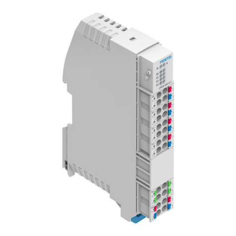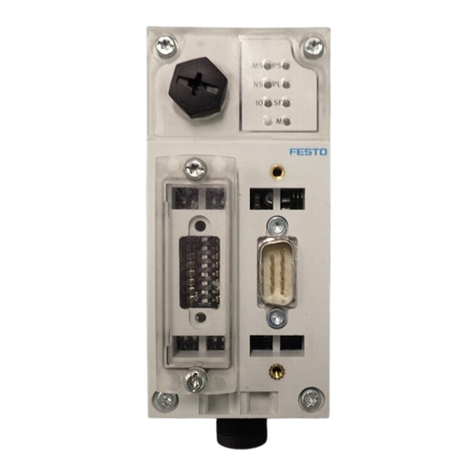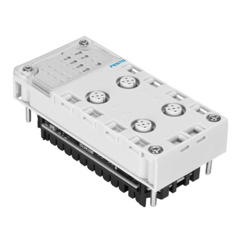
–Operation of the CPX-FVDA-P2 is permissible only in combination with the
following PROFIsafe-compatible CPX bus nodes è Bus node rating plate:
Bus node From revision Network protocol
CPX-FB131) 30 PROFIBUS
CPX-FB332) 21 PROFINET IO
CPX-M-FB342) 21 PROFINET IO
CPX-M-FB352) 21 PROFINET IO
CPX-FB432) 50 PROFINET IO
CPX-M-FB442) 50 PROFINET IO
CPX-M-FB452) 50 PROFINET IO
1) è Description of CPX-FB13...
2) è Operating instructions for CPX-(M)-FB33/34/35/43/44/45
Tab. 1: Permissible PROFIsafe-compatible CPX bus nodes
–Operation of the CPX-FVDA-P2 within valve terminals is only permissible with
the following valve types:
Valve terminal Type Valve types
MPA-S-FB-VI 32 MPA1, MPA2 on VMPA…-FB-EMG-…1)
MPA-F-FB-VI 33 MPAF1, MPAF2 on VMPA…-FB-EMG-…1)
MPA-L-FB-VI 34 All1)
VTSA-FB-VI 44 All up to width of 52 mm1)
VTSA-F-FB-VI 45 All up to width of 52 mm1)
VTSA-F-CB-VI 46 All1)
1) Malfunctions may occur if the resultant current is exceeded.
Tab. 2: Permissible valve types
–Operation of switch-off groups within valve terminals is permitted only in con-
junction with permissible pneumatics è Description of the respective valveter-
minal.
–Operation of switch-off groups in CPX terminals in the Remote I/O mode of
operation is only allowed with the following approved output modules:
Output module
CPX-4DA1)
CPX-8DA1)
CPX-8DA-H1)
CPX-8DI-8DO1)
1) Malfunctions may occur if the total current is exceeded.
Tab. 3: Permissible output modules
Output modules on the right side of the CPX-FVDA-P2, which are switched off via
CH1 or CH2, may only be supplied via the additional supply CPX-M-GE-EV-Z.
The use of a voltage relay on the right of CPX-M-GE-EV-FVO is not permitted.
–Only the following components are permitted when assembling the CPX-FVDA-
P2:
Version Component Type
1 CPX-FVDA-P2 in combina-
tion with certain manifold
and interlinking blocks of
the CPX terminal
Interlinking block CPX-M-GE-EV-FVO
Manifold block CPX-M-AB-4-M12X2-5POL
CPX-AB-8-KL-4POL
2 CPX-FVDA-P21) as part of
the pneumatic interface
of the valve terminal
VTSA‑F‑CB
Pneumatic interface VABA-S6-1-X...-F1-CB
3 Pneumatic interface VABA-S6-1-X...-F2-CB
1) Revision R04 (or a higher revision) of the output module required è Rating plate of the electronics
module CPX‑FVDA‑P2
Tab. 4: Permissible components
Further information about the supported product versions can be found in the
description CPX-FVDA-P2-... and the description of the valve terminal VTSA-F-CB.
Detailed information about the product, the supported product versions and
required software versions as well as the permissible components of the CPX ter-
minal can be found in the system description CPX-SYS-… è www.festo.com/sp.
Information about permissible configurations of the CPX terminal in
combination with the output module can be found in the catalogue
è www.festo.com/catalogue.
1.5 Foreseeable misuse
The following examples of foreseeable misuse are among those not approved as
intended use:
–Use outdoors
–Use in non-industrial areas
–Use outside the limits of the product defined in the technical data
–Unauthorised modifications
–Use in combination with consumers where switching off can result in hazardous
movements or conditions
NOTICE
The use of manifold blocks, interlinking blocks and pneumatic interfaces that are
not specified is not permissible.
NOTICE
In the following cases, the use of the output module CPX-FVDA-P2 for formation of
safety circuits is not permissible:
• In a CPX terminal equipped with CPX-FEC or CPX-CEC
• In a CPX terminal with shut-off groups containing output modules other than
those permitted
• In a CPX terminal of variant P
• In a CPX terminal with a connected valve terminal which is equipped with valve
types other than the following: VTSA, MPA-S, MPA-F è Tab. 2 Permissible valve
types
•In a CPX terminal with a connected valve terminal where a proportional-pres-
sure regulator VPPM is located in switching groups with a safety shutdown
function
• In impermissible switching configurations è Description CPX-FVDA-P2-...
NOTICE
The output module does not contain any wearing parts. Repairs are not allowed
on the output module CPX-FVDA-P2. This invalidates the certification of the
output module. Professional replacement of the electronics module by the user is
permissible.
NOTICE
In the event of damage caused by unauthorised manipulation or any form other
than the intended use, the warranty is invalidated, and the manufacturer is not
liable for damages.
1.6 Attainable safety level
With the CPX-FVDA-P2, safety functions can be implemented up to:
–Safety integrity level SIL 3 in accordance with IEC 61508
–Performance Level e, Cat. 3 in accordance with EN ISO 13849-1
–SIL claim limit SIL CL 3 in accordance with EN 62061.
The attainable safety level of the overall safety device depends on the other
components used to implement the safety function.
To maintain the safety level:
–Test the functionality of the safety device at adequate intervals.
1.7 Failures due to a common cause (Common Cause Failure – CCF)
Common cause failures cause the loss of the safety function, since both channels
(P and M) in a dual-channel system fail simultaneously.
The following measures ensure that common cause failures are avoided:
–Comply with operating voltage limits
–Comply with temperature range
è Tab. 17 Further characteristic values
è Fig. 7
–Use a maximum of 2 output channels in a common safety pilot circuit
Additional measures for avoidance of common cause failures may result from the
application.
1.8 Requirements for product use
–Make this brief description available to the design engineer, installation techni-
cian and personnel responsible for commissioning the machine or system in
which this product is used.
–Keep this brief description throughout the entire product lifecycle.
–Make sure that the specifications of the documentation are always complied
with. Also comply with the documentation for the other components and mod-
ules (e.g. bus nodes, pneumatics, etc.).
–Take into consideration the legal regulations applicable for the location as well
as:
–Regulations and standards
–Regulations of the testing organisations and insurers
–National specifications
–Remove all packaging, such as foils, caps, cardboard. The material used in the
packaging has been specifically chosen for its recyclability (exception: oiled
paper = residual waste).
–Assembly must be performed in a professionally correct manner. To maintain
the IP degree of protection:
–Screw the manifold block on tight è 4.3 Mounting the electronics module.
–Mount cable entry and seals in a professionally correct manner.
–Seal unused ports with cover caps.
–If the system had to be shut down for safety reasons such as an emergency
stop, make sure the safety controller monitors/controls all system restarts.
1.9 Technical prerequisites
General conditions for the correct and safe use of the product, which must be
observed at all times:
–Comply with the technical operating limits è 7 Technical data.
Only then is operation of the product ensured in accordance with the relevant
safety regulations.
–When connecting standard auxiliary components, also observe the specified
critical limits for temperatures, electrical data and torques.
1.10 Training of skilled personnel
The device may only be commissioned by trained, qualified control and automa-
tion technology personnel, who are familiar with:
–Installation and operation of control systems
–Applicable regulations for operating safety-related systems
