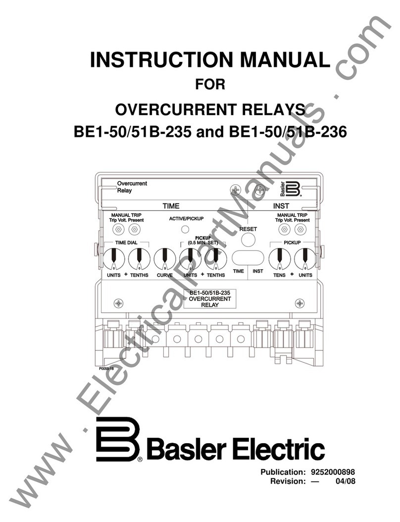
BE1-50/51B - Introduction iii
$$#
SECTION 1 GENERAL INFORMATION ....................... 1-1
Description .......................................................1-1
Application .......................................................1-1
Model Numbers ......................................................1-1
Specifications ........................................................1-3
Characteristic Curves .................................................1-11
SECTION 2 CONTROLS AND INDICATORS ................... 2-1
SECTION 3 FUNCTIONAL DESCRIPTION ..................... 3-1
General .......................................................3-1
Functional Description .................................................3-1
Sensing Input .....................................................3-1
Power Supply ....................................................3-1
Instantaneous Signal ...............................................3-1
Time Signal ......................................................3-1
Microprocessor ...................................................3-1
Power-Off Sensing ................................................3-1
Outputs .......................................................3-2
SECTION 4 INSTALLATION ................................ 4-1
General .......................................................4-1
Dielectric Test .......................................................4-1
Mounting .......................................................4-1
Panel Drilling Diagram BE1-50/51B, A1 Case (Semi-Flush Mount) ...............4-2
Outline Dimensions, BE1-50/51B, A1 Case (Semi-Flush Mount) .................4-2
Panel Drilling Diagram, S1 Case, (Projection Mount) .........................4-3
Panel Drilling Diagram, S1 Case, (Semi-Flush Mount) ........................4-3
Outline Dimensions For S1 Case (Semi-Flush Mount) ........................4-4
Panel Drilling Diagram, S1 Case, (Projection Mount) .........................4-4
Outline Dimensions, BE1-50/51B, S1 Case (Projection Mount) ..................4-5
Connections .......................................................4-6
AC Input Connections ..............................................4-6
DC Control Connections And Jumper Configuration Terminations ............4-7
BE1-50/51B Overcurrent Relay, Rear View .................................4-8
SECTION 5 TESTING ...................................... 5-1
General .......................................................5-1
Dielectric Test .......................................................5-1
Operational Test Procedure .............................................5-1
Test Equipment Required ...........................................5-1
Pickup and Timing Test Setup ........................................5-2
Target Operational Test Setup .......................................5-2
Test Procedure, Models BE1-50/51B-X05, -X06, and -X07 ..................5-3
Test Procedure, Models BE1-50/51B-X01, -X02, and -X03 ..................5-6
Setting the Relay .....................................................5-8
Periodic Tests .......................................................5-8
General .........................................................5-8
