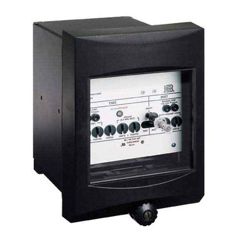
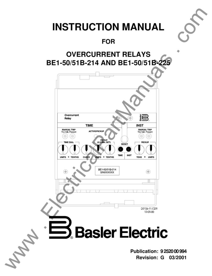
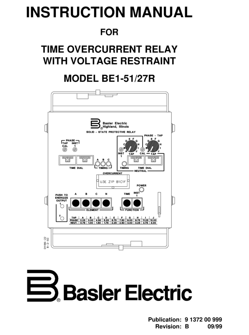
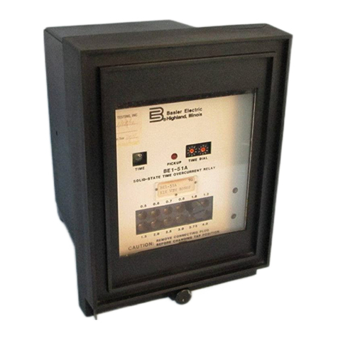
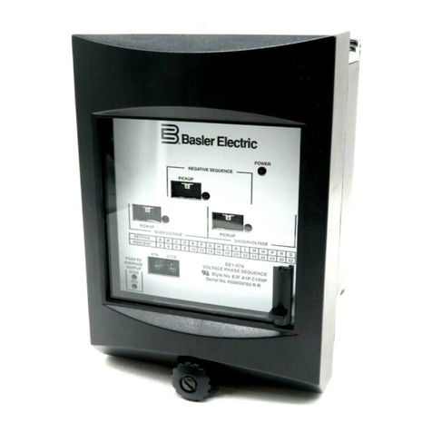
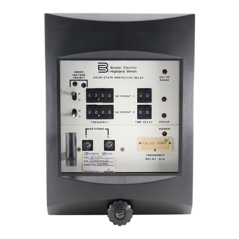
Basler BE1-25/79TR User manual

+05647%6+10/#07#.
(14
.19241(+.'
5;0%%*'%-4'%.15+0)
4'.#;
$'64
Publication: 9 2787 00 990
Revision: B 07/95

i
W A R N I N G !
To avoid personal injury or equipment damage, only
qualified personnel should perform the procedures
presented in this manual.
INTRODUCTION
This manual provides information concerning the operation of BE1-
25/79TR Sync-Check Reclosing Relays. To accomplish this, the
following information is provided.
>
>
General Information
>
>
Functional Description
>
>
Installation Information
>
>
Calibration and Testing Procedures

ii
CONFIDENTIAL INFORMATION
OF BASLER ELECTRIC COMPANY, HIGHLAND, IL. IT IS LOANED FOR
CONFIDENTIAL USE, SUBJECT TO RETURN ON REQUEST, AND WITH THE
MUTUAL UNDERSTANDING THAT IT WILL NOT BE USED IN ANY MANNER
DETRIMENTAL TO THE INTEREST OF BASLER ELECTRIC COMPANY.
First Printing: October 1994
Printed in USA
July 1995
It is not the intention of this manual to cover all details and variations
in equipment, nor does this manual provide data for every possible
contingency regarding installation or operation. The availability and
design of all features and options are subject to modification without
notice. Should further information be required, contact Basler
Electric Company, Highland, Illinois.
BASLER ELECTRIC, BOX 269 HIGHLAND, IL 62249 USA
PHONE 618-654-2341 FAX 618-654-2351

iii
CONTENTS
Section 1 GENERAL INFORMATION 1-1
Description......................................... 1-1
Capabilities ........................................ 1-1
Reclosing ...................................... 1-1
Sync-Check..................................... 1-1
Voltage Monitor .................................. 1-1
Tripping........................................ 1-1
Control Inputs ................................... 1-2
Enable Inputs ................................... 1-2
Timers......................................... 1-2
Indicators....................................... 1-2
Communications................................. 1-2
TimingFunctions.................................... 1-3
Control Inputs ................................... 1-3
Reclosing ...................................... 1-3
Tripping........................................ 1-4
Outputs ........................................... 1-5
Control......................................... 1-5
Alarm.......................................... 1-5
Application......................................... 1-5
General ........................................ 1-5
ReclosingExample............................... 1-5
Bus D or Transformer T1 Faults and Clears ........... 1-9
Bus D or Transformer T1 Faults and Fails to Clears ..... 1-9
Bus E or Transformer T2 Faults and Fails to Clears ..... 1-9
Model Numbers .................................... 1-10
Specifications ..................................... 1-11
Section 2 CONTROLS AND INDICATORS 2-1
Section 3 FUNCTIONAL DESCRIPTION 3-1
General ........................................... 3-1
BlockDiagramAnalysis .............................. 3-1
Output/Magnetics Board ........................... 3-1
Input/Logic Board ................................ 3-1
Power Supply ................................... 3-1
Modes of Operation .................................. 3-3
SettingsMode................................... 3-3
StatusMode .................................... 3-4
Reclosing Functional Description ....................... 3-5
High Speed Reclose .............................. 3-5
Parallel ........................................ 3-5
RestorePower .................................. 3-5
LineTest ....................................... 3-5
Sync-CheckFunctionDescription....................... 3-6
Sync-Check..................................... 3-6
Voltage Difference ............................... 3-7

iv
CONTENTS - Continued
CONTENTS
Section 3 FUNCTIONAL DESCRIPTION - Continued
Voltage Monitor .................................. 3-7
Slip Frequency Difference ......................... 3-9
TrippingFunction,PowerFail .......................... 3-9
ControlFunctions ................................... 3-9
Counter Enable .................................. 3-9
DrivetoLockout ................................. 3-9
DrivetoReset................................... 3-9
TimingFunctions.................................... 3-9
MasterTimer.................................... 3-9
ResetTimers................................... 3-10
LockoutTimer.................................. 3-10
RecloseTimers................................. 3-10
HSRTimer .................................... 3-10
Sync-CheckTimer .............................. 3-10
PFTimer ...................................... 3-10
CloseTDTimer................................. 3-11
LossOfPotentialTimer .......................... 3-11
SelectionFunctions................................. 3-11
HSRSync ..................................... 3-11
Start52b ...................................... 3-11
Communications ................................... 3-11
General ....................................... 3-11
RS232-C Format ................................ 3-11
Serial Port Connections and Configurations .......... 3-12
SerialCommunication ........................... 3-13
StartingCommunication .......................... 3-13
Main Menu and Activities ......................... 3-14
Section 4 INSTALLATION 4-1
General ........................................... 4-1
OperationPrecautions ............................... 4-1
DielectricTest ...................................... 4-1
Mounting .......................................... 4-2
General ........................................ 4-2
Installing Escutcheon Plates ........................ 4-4
Connections ........................................ 4-5
Section 5 TESTING 5-1
General ........................................... 5-1
Testing............................................ 5-1
Preliminary Setup Procedures ...................... 5-1
Time, Date, Settings, and Save ..................... 5-6
Timers......................................... 5-6
Control Inputs ................................... 5-8
Voltage Monitor ................................. 5-10
Voltage Difference Inhibit ......................... 5-10
v
CONTENTS- Continued
Section 5 TESTING - Continued
Sync LB and LL Inhibit ........................... 5-10
PhaseAccept .................................. 5-10
Slip Frequency Difference ........................ 5-11
Pro
g
rammableOutputs .......................... 5-11
Calibration ........................................ 5-12
SelfTest ......................................... 5-13
Loadin
g
Factory Default Settin
g
s ...................... 5-15
Section 6 MAINTENANCE 6-1
General ........................................... 6-1
In-House Repair .................................... 6-1
Stora
g
e ........................................... 6-1
Section 7 CHANGE INFORMATION 7-1

1-1
SECTION 1
GENERAL INFORMATION
DESCRIPTION
BE1-25/79TR Sync-Check Reclosing Relays are microprocessor based relays that provide automatic
reclosing for transmission line systems, utility interties, and distribution systems with cogeneration. BE1-
25/79TR relays provide one or two shot reclosing capabilities with sync-check and voltage monitoring
functions. To provide the required and perhaps changing characteristics for your specific system, theBE1-
25/79TR relays are field programmable via contact sensing inputs. Relay timing is programmed using the
relay front panel mounted switches and visual display or remotely using communication ports mounted on
the frontand rear panels. Communication through the front and rear ports requires a remotecomputer with
modem software. These capabilities are required to fully automate your transmission line system.
CAPABILITIES
BE1-25/79TR relays are similar in principle tomechanical repeatcycletimers wherevarious operationsare
permitted as the cam is rotated. The capabilities of this relay are equivalent to and exceed mechanical
relays used in automated transmission line systems. BE1-25/79TR relays have the following capabilities.
Reclosing
One or two shots.
High speed reclose (in cycles) and high speed reclose with sync-check supervision.
Parallel (live line/live bus) and parallel with sync-check and voltage monitor.
Restore power (live line and dead bus).
Line test (dead line and live bus).
Sync-Check
Checks phase angle between line and bus.
Phase window setting.
Slip frequency window setting.
Independent of reclosing sequence.
Voltage Monitor
Live line.
Dead line.
Live bus.
Dead bus.
Delta voltage.
Tripping
Trip breaker when both line and bus are dead (power fail condition).
Trip function enabled by power fail (PF) external contact sensing input.

BE1-25/79TR General Information
1-2
Control Inputs (External Contact Sensing Inputs)
CE - Master timer enable(enables or freeze all timers).
DTL - Drive to lockout.
DTR - Drive to reset.
PF - Power fail tripping enable/disable.
BLK - Block high speed reclose for three-phase faults.
Enable Inputs (External Contact Sensing Inputs)
LT1 - Line test one.
LT2 - Line test two.
RP1 - Restore power one.
RP2 - Restore power two.
PAR - Parallel.
52b - Breaker b seal.
HSR - High speed reclose.
Timers
MASTER - Window for reclosing sequence.
RST1, RST2 - Reset timers.
LO - Lockout timer for failed reclose.
LT1, LT2, RP1, RP2, PAR - Reclose timers.
HSR - High speed reclose timer.
SYNC - Sync-check timer.
PF - Dead line and bus condition timer.
LOP - Loss of potential with closed breaker.
Indicators
There are five indicator types or categories and all are mounted on the front panel.
Visual Display - Twelve character display to monitor function, status, and settings.
Targets - Eight red LEDs.
Control - Four yellow LEDs.
Timing - Seven green LEDs.
Status - One green and four yellow LEDs.
Communications
CommunicationthroughfrontorrearpanelmountedRS 232-Cconnectorsrequiresa remotecomputerwith
modem software in a VT-100 compatible terminal mode. Communication allows a remote or local user to
view current internal relay parameters (parameters in this case refer to the operational status of specific
components such as RAM, ROM, power supply, voltage magnitudes and sync check parameters), select
relay settings, review and reset event record reports data, and view both summary and detailed reports.
Figure 1-1 shows the menu driven flow diagram paths and the required keystrokes to enter and exit each
screen. Main activities (screens) are:
Diagnostics (password protected)
Review/reset maintenance values
Programmable outputs
Reports
Review/edit settings (password protected)

BE1-25/79TR General Information
1-3
Figure 1-1. Communication Terminal Screens Flow Diagram
TIMING FUNCTIONS
Control Inputs
Some control inputs (external contact sensing inputs) are associated with both control and timing and may
be used to enable or disable relay functions. An open CE contact sensing input freezes all timers. When
the CE input is closed, the timers resume timing. When PF contact sensing input is closed (enabled), the
breaker is closed (52b open), and both bus and line voltages are dead, PF timing is initiated . When BLK
contact sensing input is closed, high speed reclosing attempts are blocked. When the DTL or DTR inputis
closed, the relay is driven to lockout (DTL) or reset (DTR).
Reclosing
Timing for reclosing begins when either the breaker opens (52b closes) with an intitiate contact input (LT1,
LT2, RP1, RP2, or PAR) closed or the high speed reclose (HSR) input closes momentarily (refer to Figure
1-2fortimingrelationships). Eitheroftheseconditionscausethemastertimerandallreclosetimerstobegin
timing. ThesettingSTART52ballowsthemastertimerandreclosetimerstostarttimingonlyon52b closing
without an additional initiate contact input closed.
Mastertiming definesaperiod oftime(window)thata recloseoutputmay begiven. One ormorereclosings
maybe initiatedifreclose timerstimeoutduringthemastertimingwindow. Timer durationsareestablished
by programming the relay using the front panel mounted switches and visual display.
Reclose action occurs when the conditions for reclose are satisfied and the particular reclose timer times
out. Conditions associated with each reclose timer are established during setup. They include live or dead
conditionsonthelineandbusand alsothestatusofthebreaker. PARreclosetimeralsoincludesconditions
for delta voltage and phase angle across the open breaker.

BE1-25/79TR General Information
1-4
A failed reclose can be detected when the breaker does not open (52b stays closed) after the breaker
operate time (CLOSE TD setting) and the Lockout Timer time delay expire (see Figure 1-3). If 52b does
not open (indicating a unsuccessful reclose) before the Lockout Timer expires, the relay will go to lockout.
At that time, the breaker must be closed manually.
After the master timer expires, the status of the breaker (52b contact) is checked. If the breaker remains
closed for the time established for RST1 timer, then the relay is reset.
Figure 1-2. PAR (LL/LB) Reclosing Timing Chart
Figure 1-3. Failed Reclose Lockout Timing Chart
Tripping
PowerFail timingisinitiatedwhenbothlineandbus aredead, PFcontactsensinginputisclosed (enabled),
and the breaker is closed. If these conditions remain after the PF timer expires, a trip output is issued. If
the breaker is opened externally with a dead line and dead bus condition, all enabled timers will be frozen
until the breaker is closed manually or until any voltage potential is reapplied.

BE1-25/79TR General Information
1-5
OUTPUTS
Control
Form A output contacts (CLOSE) provide for closing of the breaker during the reclose sequence. The
maximum duration for the CLOSE output is determined by the CLOSE TD setting adjustable from 1 to 999
seconds in one setting increments.
Form A output contacts(TRIP) are provided to trip the breaker for a dead line and dead bus condition when
the power fail feature is selected.
Form A output contacts (SYNC) are provided for sync-check/voltage monitor functions. When the phase
angle and voltage are within the limits set for permitting a reclosure and the sync time delay setting
(adhustable from 1 to 999 cycles ine one cycle increments) expires, the sync output contacts close. This
output may be used to supervise other devices in the station and is independent of the master timer.
N.O. or N.C. selectable memoryoutput contactsare provided for LT1, LT2, RP1, and RP2. When a reclose
occurs, the associated relay is energized and latched. The relay remains latched until the reclosing
sequencereturnstoreset. Theseoutputsareusedinlogicschemes requiringmore thanone BE1-25/79TR
to test the bus. These four outputs may be redefined to indicate live or dead voltage monitor conditions.
Alarm
Three Form A programmable output contacts (PROG1, PROG2, and PROG3) are provided to indicate
systemvoltageconditions,lossofpotential,Lockout,reclosinginprogress,parallelandhighspeedreclosing
targets.
Form B output contacts are provided for a relay trouble alarm (RT ALM). RT ALM contacts are held open
unless there is a power supply failure or an internal microprocessor failure.
APPLICATION
General
BE1-25/79TR relays are suitable for use in any automatic transmission reclosing system. BE1-25/79TR
relays could also be used in distribution applications even though the full capabilities of the relay would not
be used.
Parallel with sync-check supervision is a high speed function suitable for blocking high speed reclosing on
out-of-stepconditions. Thisapplicationcanbeusedontransmissionlinesconnectedtogenerationsystems.
By delaying the reclosing on one end until the other end has energized the line, the phase angle of the
voltages can be compared. If the angle exceeds a phase window value, the high speed reclosing (and
paralleling) can be blocked.
BE1-25/79TR relays can be programmed to operate with the breaker open for a live line/live bus condition
and the parallel function disabled.
With a dead line and dead bus condition, the power failure function can be used to trip the breaker and
freeze any reclose timing in progress.
Added versatility for the relay is provided by the counter enableinput. This contact sensing input interrupts

BE1-25/79TR General Information
1-6
Figure 1-4. Loop Station Application Example
and freezes the reclose timers any time this input is opened regardless of voltage monitor conditions.
Reclosing Example
Automated reclosing applications can be as simple or complex as your particular station requires. All
connections between BE1-25/79TR relays,monitoring inputs,andcontactsensing inputs are not shown in
our example.
Our example, Figures 1-4 illustrates a typical three transformer looped station automated reclosing
application. Inthisexample,fourBE1-25/79TRrelaysareused. BE1-25/79TRrelaynumber1isconnected
across breaker 52-1 (Line 1 potential transformer (PT) feeds the relay line input and bus D PT feeds the
relay bus input). BE1-25/79TR relay number 2 is connected in a similar manner for breaker 52-2. BE1-
25/79TR relay number 3 is connected to motor operated switch 89-4 with bus D PT feeding the line input
and bus E PT feeding the bus input. BE1-25/79TR relay number 4 is connected in a similar manner for
motor operated switch 89-5, Bus F, and Bus E. When reclosing 89-4 and 89-5, 89-4 is set to close first.
Figures 1-5 through 1-8 illustrate connections for the four BE1-25/79TR relays in our example application.
Legend (for Figures 1-5 through 1-8)
43/A-Auto/Manual Switch 43C/ON-Carrier Switch ON
52b-Breaker Position 86-Lockout Relay
94-Aux Tripping Relay BLK- Block High Speed Reclose
CE-Master Timer Enable F/FCC-Power Fail Feature Cut-Out
H/FCC-High Speed Feature Cut-Out HRC- High Speed Reclose Cancel
HRI-High Speed Reclose Initiate HSR-High Speed Reclose Enable
LT1-First Line Test Enable P/FCC-Parallel Feature Cut-Out
PAR-Parallel Enable PF-Power Failure Enable
R/FCC-Restore Feature Cut-Out RP1-First Restore Power Enable
T/FCC-Test Feature Cut-Out

BE1-25/79TR General Information
1-7
Figure 1-5. Application Example BE1-25/79TR, Relay 1
Figure 1-6. Application Example BE1-25/79TR, Relay 2

BE1-25/79TR General Information
1-8
Figure 1-7. Application Example BE1-25/79TR, Relay 3
Figure 1-8. Application Example BE1-25/79TR, Relay 4

BE1-25/79TR General Information
1-9
Bus D or Transformer T1 Faults and Clears
When a bus D or T1 fault occurs, both power circuit breakers and both motor operated switches trip
open. Lines one and two are live and RP1 functions on BE1-25/79TR-1 and -2 relays are enabled
through the normally closed contacts of RP memory 1 relays. Both BE1-25/79TR-1 and -2 relays
receive the 52b inputs and both BE1-25/79TR-1 and -2 relays provide reclose output pulses to the
power circuit breakers. Both breakers close.
BE1-25/79TR-3 and -4 relays for the motor operated switches now have live line and dead bus inputs,
RP1 enables, and 52b inputs from the Form B contacts on the motor operated switches. Motor
operated switch 89-5 BE1-25/79TR-4 relayalso has theparallel inputenabled. RP1 timer on the relay
for 89-4 times out and the relay provides a reclose pulse for 89-4. 89-4 recloses. When the RP1 timer
and sync-check supervision (parallel) allows,the BE1-25/79TR-4 relay for 89-5 parallelsand provides
the reclose pulse for 89-5. 89-5 successfully recloses. All reset timers in all four BE1-25/79TR relays
expire and all four relays reset.
Bus D or Transformer T1 Faults and Fails To Clear
When a bus D or T1 fault occurs, both power circuit breakers and both motor operated switches trip
open. Lines one and two are live and RP1 functions on BE1-25/79TR-1 and -2 relays are enabled
through the normally closed contacts of RP memory 1 relays. Both BE1-25/79TR-1 and -2 relays
receive the 52b inputs and both BE1-25/79TR-1 and -2 relays provide reclose output pulses to the
power circuit breakers. Both breakers close. Breaker 52-1 closes into a fault and both breakers open.
LockouttimeronBE1-25/79TR-1relay expiresbecause thebreakeris stillopen afterthereclosepulse
and the relay drives to lockout. BE1-25/79TR-3 relay 52b input is present but the line potential input
is not live. When the master timer expires, the relay drives to lockout. During this time, RP2 timer in
BE1-25/79TR-2 is enabled by the input through the RP memory 1, normally closed contacts of BE1-
25/79TR-4 relay (motor operated switch 89-5). RP2 timer times out and breaker 52-2 successfully
recloses.
RP1 timer in BE1-25/79TR-4 relay for the motor operated switch 89-5 is not enabled because RP
memory 1 normally closed contacts are open. RP2 input is enabled through the RP memory 1,
normallyclosed contactsofBE1-25/79TR-3relay(motoroperatedswitch89-4).RP2timesoutand the
relayprovides areclosepulsefor89-5. 89-5 successfullyrecloses andenergizesbusE. Because bus
Ewasdeadbeforethereclose pulse,parallel functionwasnotenabled. ResettimersinBE1-25/79TR-
2 and -4 relays expire and both relays reset.
Bus E or Transformer T2 Faults and Fails To Clear
When a bus E or T2 fault occurs, both power circuit breakers and both motor operated switches trip
open and all the customers served by the loop station loose power. Lines one and two are live and
restore power functions on BE1-25/79TR-1 and -2 relays are enabled. Both BE1-25/79TR relays
receivethe 52binputsand bothBE1-25/79TRrelays providereclose outputpulsestothe powercircuit
breakers. Both breakers close. Customers served by buses D and F have power quickly restored.
Now for bus E. BE1-25/79TR-3 and -4 relays for the motor operated switches now have live line and
dead bus inputs, RP1 enables, and 52b inputs from the Form B contacts on the motor operated
switches. RP1 timer on the relay for 89-4 times out and the relay provides a reclose pulse for 89-4.
89-4 recloses into a fault on bus E and 89-4 opens. BE1-25/79TR-3 relay for 89-4 drives to lockout
because the 52b input is still presentand the lockout timer expires. BE1-25/79TR-4 relay for 89-5 has
the 52b input present but RP1 can not be enabled because BE1-25/79TR-2, RP memory 1 normally
closed contacts are open. RP2 can notbe enabled because BE1-25/79TR-3, RP memory 1 normally
closed contacts are open. BE1-25/79TR-4 drives to lockout, and only customers on bus E loose
service.

BE1-25/79TR General Information
1-10
MODEL NUMBERS
Model number variation in BE1-25/79TR Sync-Check Reclosing Relays are specified by the lastthree
digits in the part number. Table 1-1 provides model number, type of relay, mounting style, operating
power supply voltage, and communications capability.
Table 1-1. Part Number Cross Reference
Part Number Description
9 2787 00 100 Three-phase, 120 Vac/125 Vdc, Horizontal Mount
9 2787 00 101 Three-phase, 48 Vdc, Horizontal Mount
9 2787 00 102 Three-phase, 120 Vac/125 Vdc, Vertical Mount
9 2787 00 103 Three-phase, 48 Vdc, Vertical Mount
9 2787 00 104 Single-phase, 120 Vac/125 Vdc, Horizontal Mount
9 2787 00 105 Single-phase, 48 Vdc, Horizontal Mount
9 2787 00 106 Single-phase, 120 Vac/125 Vdc, Vertical Mount
9 2787 00 107 Single-phase, 48 Vdc, Vertical Mount
9 2787 00 200 Three-phase, 120 Vac/125 Vdc, Horizontal Mount Relay (9 2787 00 100) with
LPTR Test Box (9 2787 08 100)

BE1-25/79TR General Information
1-11
SPECIFICATIONS
Power Supply Inputs
(Range) +125 Vdc (62 to 150 Vdc), or 120 Vac (90 to 132 Vac, 50/60 Hz).
(Burden) Burden at 60 Hz, 120 Vac is 26 VA, and burden at 125 Vdc is 14
watts. Burden at 50 Hz, 110 Vac is 25 VA.
Voltage and Phase
Sensing Inputs
(Range) Nominally rated at 60 Hz with a range of 55 to 65 Hz and 1 to 135
Vac. Nominally rated at 50 Hz with a range of 45 to 55 Hz and 1 to
120 Vac. Maximum continuous voltage rating is 160% of nominal.
(Burden) Maximum burden of 1 VA per phase to 125% of nominal voltage.
(Configuration) Bus and line voltage sensing inputs are isolated. Two inputs are
required. One for line potential and one for bus potential.
Phase Angle
(Selection Accuracy) ±1.0
for a nominal input frequency of 50/60 Hz, with an input range
of 10 to 135 volts at 25
C.
(Setpoint Accuracy) ±1.0
from a reference measurement at 25
C, at nominal input
frequency and levels, over the specified operating range of
temperature and input voltages.
Voltage Difference
(Range) Continuously adjustable over the range of 1 to 135 Vac.
(Accuracy) ±5.0% or ±1.0 V whichever is greater.
Line and Bus Voltage
Monitor
(Range) Continuously adjustable over the range of 10 to 135 Vac.
(Accuracy) ±5.0% or ±1.0 V whichever is greater.
Contact Sensing Inputs
User-suppliedcontactswithaminimumratingof0.05Aat250Vdcare requiredatallcontactsensing
inputs. Non-isolated sensing requires an externally applied dc sensing
voltage equal to the nominal voltage of the relay power supply input.
Contact recognition is adjustable from 8 to 200 milliseconds in 4
millisecond increments (actual setting times 4 milliseconds).
Line Test 1 (LT1).
Line Test 2 (LT2).
Restore Power 1 (RP1).
Restore Power 2 (RP2).
Parallel Enable (PAR).
Power Failure Enable (PF).
52b = or breaker b seal.

BE1-25/79TR General Information
1-12
Counter Enable (CE).
Contact Sensing Inputs - Continued
High Speed Enable (HSR).
Block High Speed Reclose (BLK) for 3 phase faults.
Drive to Lockout (DTL).
Drive to Reset (DTR).
Serial Port Communications Front and rear panel mounted RS 232-C connectors (9-pin, D
subminiature female) for setting, testing, and data collection.
Time Delays Refer to Table 1-2. Timing tolerance for HSR and SYNC timers is
±5% or two cycles, whichever is greater. All other timer tolerances
are ±5% or 50 milliseconds, whichever is greater.
Table 1-2. Time Delay Ranges
Number of Delays Function Range
2 Line Test (LT1, LT2) 1-999 seconds
2 Restore Power (RP1, RP2) 1-999 seconds
1* Parallel (PAR) 1-999 seconds
1 Sync-Check (SYNC) 1-999 cycles
1 High Speed Reclose (HSR) 1-999 cycles
1** Power Fail (PF) 1-99 seconds
2 Reset Time (RST1, RST2) 1-999 seconds
1 Lockout Time (LO) 1-999 seconds
1*** Master Time (MASTER) 1-999 seconds
1 Close Output (CLOSE TD) 1-999 seconds
1 Loss of Potential (LOP TD) 0.01-9.99 seconds
* If the breaker is intended to operate open (parallel disabled) then the relay will go to reset
after the master timer times out and RST2 timer expires. The bus and line will both be
energized with the PAR input open.
** The power failure function is a tripping function and will not start the master timer.
*** Master timerusedis similar in principle to the mechanical repeat cycle (R.C.) timer in which
various operations are permitted as the cam rotates. If lockout hasnot been reached in the
preset time allotted,the master timer will time out and determine whether to go to lockout or
reset depending uponthe state ofthe breakerand ifthe bus and line are Livewith PARinput
disabled.
Outputs All outputs are MOV protected.
(Isolated) Trip, close, sync-check, relay trouble alarm (RT ALM) and memory.
Trip One tripping contact with N.O. configuration.
Close One closing contact with N.O. configuration.
Sync The sync-check (PAR) function with voltage measuring circuits has
one output relay with a N.O. configuration.
Memory There are four memory output relays, each with selectable N.O. or
N.C. contacts for line test or restore power.

BE1-25/79TR General Information
1-13
Outputs - Continued
RT ALM One N.C. output relay that closes for internal microprocessor failure
or power supply failure.
PROG There are three N.O. programmable outputs available to indicate
voltage monitor conditions, targets and alarms.
(Rating) Output contacts are rated as follows:
Resistive
120/240 Vac Make 30 A for 0.2 seconds, carry 7 A continuously, break 7 A.
250 Vdc Make and carry 30 A for 0.2 seconds, carry 7 A continuously, break
0.3 A.
Inductive
120/240 Vac, Break 0.3 A, inductance + resistance (L/R) ratio = 0.04.
125/250 Vdc,
Indicators
(Targets) Eight LED's (red) on the front panel status display. The targets are:
High Speed Reclose (HSR).
Power Failure (PF).
Line Test 1 (LT1).
Line Test 2 (LT2).
Restore Power 1 (RP1).
Restore Power 2 (RP2).
Parallel (PAR).
Lockout (LO).
(Timing) Seven timing LED's (green) are used to indicate when a function is
timing. The LED's are:
Line test 1 (LT1).
Line test 2 (LT2).
Restore Power 1 (RP1).
Restore Power 2 (RP2).
Parallel (PAR).
Power Failure (PF).
Lockout (LO).
(Status) One LED (green) and four LED's (yellow) indicate relay status. The
green LED (RST) indicates the relay is in reset. The four yellow
LED's indicate the bus and line status. They are:
Dead Bus (DB).
Live Bus (LB).
Dead Line (DL).
Live Line (LL).

BE1-25/79TR General Information
1-14
Indicators - Continued
(Control) Four LED's (yellow) indicate relay control status.
Trip.
Close.
25 (Sync-Check Function).
Counter Enable (CE).
Isolation AllterminalshaveMOVsuppressorsexcept thecommunication,line,
andbusterminals. Maximumappliedvoltagemustbenogreaterthan
300voltswhereMOVsuppressorsare used. 1500Vacat60hertzfor
one minute may be applied across line and bus input terminals,
between circuit groups, and between circuit groups and chassis
ground in accordance with IEC 255-5 and ANSI/IEEE C37.90-1989
(Dielectric Test).
Surge Withstand Capability Qualified to ANSI/IEEE C37.90.1-1989 Standard Surge Withstand
Capability (SWC) Tests for Protective Relays and Relay Systems.
Fast Transient All inputs and outputs except for communication ports are qualified
to ANSI/IEEE C37.90.1-1989.
Radio Frequency Field tested using a five watt, hand held transceiver operating at
Interference(RFI) randomfrequenciescenteredaround144MHzand440MHz,with the
antenna allocated six inches from the relay in both horizontal and
vertical planes.
Temperature Operating Range
-40
C (-40
F) to 70
C (158
F).
Storage Range
-65
C (-85
F) to 100
C (212
F).
Impulse Test Qualified to IEC 255-5.
Weight 13.7 pounds maximum.
Case Size Horizontal mount. 3.50 inches (2 rack units) high x 19 inches wide.
Vertical mount. 3.50 inches wide x 19 inches high.
Required depth for mounting the relay is adjustable to either 7.37 or
8.37 inches by adjusting mounting flange location.
Table of contents
Other Basler Relay manuals

Basler
Basler BE1-50/51M-100 Series User manual

Basler
Basler BE1-59N User manual

Basler
Basler BE1-51/27R User manual

Basler
Basler BE1-50/51B-232 User manual

Basler
Basler BE1-DFPR User manual

Basler
Basler BE1-67N User manual

Basler
Basler BE1-50/51B-229 User manual

Basler
Basler BE1-700C User manual

Basler
Basler BE1-59NC User manual

Basler
Basler BE1-50/51B-219 User manual

Basler
Basler BE1-59N User manual

Basler
Basler BE1-50/51B-218 User manual

Basler
Basler BE1-50 User manual

Basler
Basler BE1-47N User manual

Basler
Basler BE1-79A User manual

Basler
Basler BE1-59N User manual

Basler
Basler BE1-50BF User manual

Basler
Basler BE1-51/27R User manual

Basler
Basler BE1-59N User manual

Basler
Basler H12345678 R U User manual