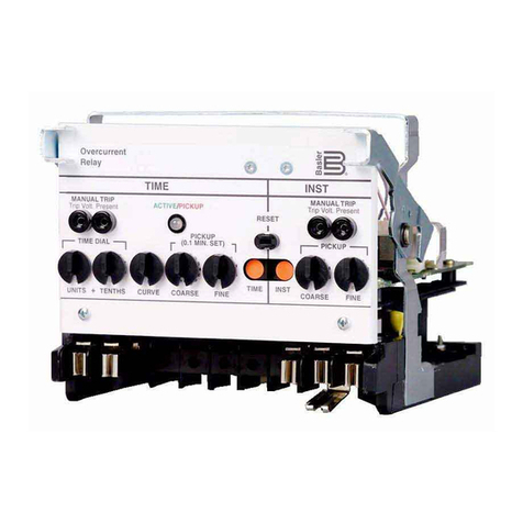
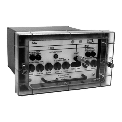
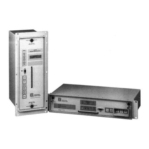
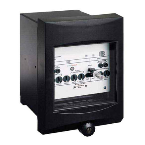
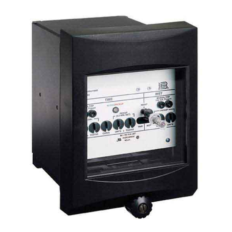
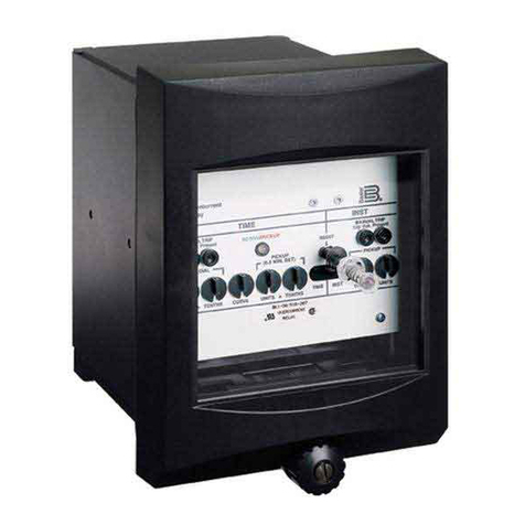
Basler BE1-50BF User manual

+05647%6+10/#07#.
(14
$4'#-'4(#+.74'4'.#;
/1&'.$'$(
2WDNKECVKQ
4GXKUKQ '

BE1-50BF Introduction i
W A R N I N G !
Toavoidpersonalinjuryorequipmentdamage,onlyqualifiedpersonnelshouldperform
the procedures presented in this manual.
INTRODUCTION
ThismanualprovidesinformationconcerningtheoperationandinstallationoftheBE1-50BFBreakerFailure
Relay. To accomplish this, the following is provided.
• Specifications
• Functional description
• Mountin
g
information
• Testin
g
information

ii BE1-50BF Introduction
CONFIDENTIAL INFORMATION
OF BASLER ELECTRIC COMPANY, HIGHLAND, IL. IT IS LOANED FOR CONFIDENTIAL USE, SUBJECT
TO RETURN ON REQUEST, AND WITH THE MUTUAL UNDERSTANDING THAT IT WILL NOT BE USED
IN ANY MANNER DETRIMENTAL TO THE INTEREST OF BASLER ELECTRIC COMPANY.
It is not the intention of this manual to cover all details and variations in equipment, nor
does this manual provide data for every possible contingency regarding installation or
operation. The availability and design of all features and options are subject to
modification without notice. Should further information be required, contact Basler
Electric Company, Highland, Illinois.
First Printing: April 1986
Printed in USA
© 1998 Basler Electric Co., Highland, IL 62249
August 1998
BASLER ELECTRIC
ROUTE 143, BOX 269
HIGHLAND, IL 62249 USA
http://www.basler.com, [email protected]
PHONE 618-654-2341 FAX 618-654-2351

BE1-50BF Introduction iii
CONTENTS
Section1 GENERALINFORMATION......................................... 1-1
Description...................................................... 1-1
TripTiming................................................... 1-1
Model and Style Number ........................................... 1-2
StyleNumber................................................. 1-2
SampleStyleNumber .......................................... 1-2
Specifications.................................................... 1-3
Section 2 HUMAN-MACHINE INTERFACE .................................... 2-1
Controls and Indicators ............................................ 2-1
Section 3 FUNCTIONAL DESCRIPTION ...................................... 3-1
General ........................................................ 3-1
Functional Description ............................................. 3-1
ContactSensing .............................................. 3-1
Instantaneous Output - Optional .................................. 3-2
ControlTimer................................................. 3-2
Timer T1 and T2 .............................................. 3-2
Field Programmable Logic ....................................... 3-2
Outputs and Targets ........................................... 3-2
CurrentSensing............................................... 3-3
CurrentPickupDetector ........................................ 3-3
CurrentPickupIndicator ........................................ 3-3
CurrentPickupOutput.......................................... 3-3
PickupSettings ............................................... 3-3
Power Supply ................................................ 3-3
Power Supply Status Contacts ................................... 3-3
Section4 INSTALLATION.................................................. 4-1
General ........................................................ 4-1
RelayOperatingPrecautions ........................................ 4-1
DielectricTest ................................................... 4-1
Mounting ....................................................... 4-1
Connections ..................................................... 4-5
Section5 TESTING ....................................................... 5-1
General ........................................................ 5-1
Operational Test Procedure ......................................... 5-1
Section 6 MAINTENANCE ................................................. 6-1
General ........................................................ 6-1
In-House Repair .................................................. 6-1
Storage ........................................................ 6-1
Section 7 MANUAL CHANGE INFORMATION .................................. 7-1
Changes ........................................................ 7-1

BE1-50BF General Information 1-1
SECTION 1 • GENERAL INFORMATION
DESCRIPTION
BE1-50BF Breaker Failure Relays are three-phase, solid state relays designed to provide protection and
security for the power system against failure of the monitored breaker.
Breakerfailurerelayingistheuseofacurrentmonitoringrelaytodeterminewhether ornot currentcontinues
to flow into a faulted circuit some time after a circuit breaker has been instructed to interrupt the circuit. In
the event that current continues to flow into the faulted circuit (after a defined period of time has elapsed
sufficientforthebreakertohaveinterruptedthecurrent),thenthecircuitbreakerisconsideredtohavefailed,
and steps must be initiated to trip the next set of breakers in the power system. The back up scheme must
be designed to isolate both the faulted circuit and the failed breaker.
Following are several reasons why a breaker fails to clear a fault:
Trip circuit can be open (broken wire, blown fuse, open trip coil).
Interrupting mechanism can stick, leaving a single phase of a three-phase circuit connected.
Interrupter can flash-over due to the loss of dielectric strength through contamination or damage.
Operating mechanism can fail to operate.
Breaker failure relays detect these conditions and initiate contingency or back up procedures.
Typically, breaker failure protection is applied to transmission and subtransmission systems. However,
breaker failure protection may be applied to any portion of the power system where failure of a circuit
breaker to operate properly could result in severe system damage or instability.
Trip Timing
Within the relay are two timers that control operation of the device. Timer 1 defines the delay time between
recognition of the breaker trip signal and the interrogation of the current monitoring circuits for the presence
of current. Adjustment range for this timer is 18 to 500 milliseconds.
At the same time that timer 1 is initiated, the control timer is also initiated. Figure 1-1 illustrates the trip
timing relationships. The purpose of the control timer is to increase security by limiting the response time
of the relay to a short period following any given attempt to interrupt the breaker. The control timer also
terminates the closure of the BF output relays, and breaks the seal of the seal-in circuit (if used).
Breaker failure initiate (BFI) input seal-in is selected by closing printed circuit board switch S1-3 (refer to
Section 2 for location). This selection may be required when current from an isolated weak source cannot
be depended on to maintain the minimum signal level to the protective relays initiating the BFI input. Such
a condition can occur when the fault voltage is depressed to zero. The seal-in feature may also counteract
contact bounce.
An optional supervisory contact input to the BE1-50BF relay may be specified. When the supervisory
contact input is specified, a third timer (timer 2) is built into the relay. Timer 2 (plus associated circuitry
together with the supervisory contact) duplicates the corresponding features of the timer 1 system. This
addition allows different breaker failure times for different types of failures.
As an example, it might be desirable to use a shorter tripping time if the breaker mechanism fails to operate
(all three breaker poles failed to clear the fault). If the mechanism did operate, but only one of the poles
failed to clear, a longer breaker failure time might be appropriate. This protection can be provided by
connecting a 52a contact of the breaker to the supervisory contact input and setting the delay on timer 2
shorter than timer 1. If the breaker mechanism failed to operate, the breaker failure relay would be
controlled by timer 2. If the breaker mechanism did operate, timer 2 would (in time) reset, and the breaker
failure relay would be controlled by timer 1.
1-2 BE1-50BF General Information
This situation requires the following conditions.
52a contact must be supervised by the BFI contact input.
Seal-in feature must not be used.
Switch S1-4 on the printed circuit board (refer to Section 2 for location) must be closed.
Figure 1-1. Timing
MODEL AND STYLE NUMBER
Style Number
Electrical characteristics and operational features included in a specific relay are defined by the relay style
number. Themodel numberandstyle numberappearon thefrontpanel, drawoutcradleand insidethecase
assembly. Model number BE1-50BF, designates the relay as a Basler Electric Class 100 Breaker Failure
Relay. Refer to Figure 1-2 for the style number identification chart.
Sample Style Number
To determine the features in a BE1-50BF relay, style number F3F E1J A4S1F, refer to the style number
identification and the following example.
FThree-phase sensing input type.
3Sensing input range 1.0 to 8.0 amperes for all phases.
FThree output relays with normally open contacts.
E1 Definite Timing.
JPower supply operates from 125 Vdc or 100/120 Vac.
AInternally operated targets.
4Non-isolated contact sensing.
SPush-to-energize outputs (pushbuttons).
1Instantaneous Trip.
FSemi-flush mounting.

BE1-50BF General Information 1-3
I
Kt
Figure 1-2. Style Number Identification Chart
SPECIFICATIONS
The BE1-50BF Breaker Failure Relay has the following features and capabilities.
Current Sensing Maximum burden of 1 VA per phase at range maximum, 50/60 Hz.
Operable over a frequency range of 40 to 70 Hz. Maximum continuous
current: 5 A for sensing range of 0.25 to 2.0 A; 10 A for sensing range of
1.0 to 8.0 A. Maximum one second current: 300 A.
For ratings other than one second, the rating may be calculatedas follows:
where t = the time in seconds, and K = 90,000.

1-4 BE1-50BF General Information
Dropout Above 98% of actual pickup level.
Current Detector Reset Less than 1 millisecond.
Pickup Range Continuously adjustable over the range defined by the style number with
independent ranges and adjustments for phase and neutral pickup.
Pickup Accuracy +2% or +40 mA of pickup setting, whichever is greater.
Pickup Tracking Accuracy 0.25 to 2.0 A range — Whichever is greater, 0.025 A or 2% between any
(Phase-to-Phase) two phases.
1.0 to 8.0 A range — Whichever is greater, 0.10 A or 2% between any two
phases.
Contact Recognition Time Less than 2.5 milliseconds.
Adjustment Range of 150 to 600 milliseconds.
Control Timer
Adjustment Range of 18 to 500 milliseconds.
Timer 1 and (optional)
Timer 2
Energizing Time of Output Approximately 8 milliseconds.
Relay
Timing Test Points Oscilloscope test points are provided on the front panel for precise
checking of the control timer, as well as timer 1. These nominal 10 V test
points are optically coupled to the logic circuits to provide 1500 V isolation.
Contact Sensing The sensing circuits require user-supplied contacts with a minimum rating
of 0.05 A at 250 Vdc. Sensing current is supplied by the relay in style with
isolated sensing. Styles with non-isolated sensing require an applied
sensing voltage equal to the relay dc power supply input rating.
Contact Sensing Burden Burden per contact for non-isolated sensing depends on the power supply
type. Refer to Table 1-1.
Table 1-1. Burden (Nominal) Per Non-isolated Sensing Contact
Power Supply Type J K L Z
Nominal Burden Per Input 3.5 W / 5.5 VA 3.5 W 1.25 W 7.0 W / 20 VA
Target Indicators Magnetically latched, manually reset targets indicate that an output relay
has energized. Either internally operated or current operated targets may
be specified. Current operated targets require a minimum of 0.2 A in the
output trip circuit, and are rated at 30 A for 1 second, 7 A for 2 minutes,
and 3 A continuously.
PowerSupply Power forthe internalcircuitrymay bederivedfrom acordc external power
sources. Refer to Table 1-2.

BE1-50BF General Information 1-5
Table 1-2. Power Supplies
Type Nominal Input Voltage Input Voltage
Range Burden at
Nominal
K (Mid Range) 48 Vdc 24 to 150 Vdc 6.0 W
J (Mid Range) 125 Vdc
120 Vac 24 to 150 Vdc
90 to 132 Vac 6.0 W
15.0 VA
L (Low Range) 24 Vdc 12†to 32 Vdc 5.3 W
Z (High Range) 250 Vdc
240 Vac 62 to 280 Vdc
90 to 270 Vac 6.0 W
15.0 VA
†Type L power supply initially requires 14 Vdc to begin operating. Once operating, the voltage
maybe reduced to 12 Vdc and operation will continue.
Output Circuits Output contacts are rated as follows:
Resistive:
120/240 Vac Make 30 A for 0.2 seconds, carry 7 A continuously, and break 7 A.
125/250 Vdc Make 30 A for 0.2 seconds, carry 7 A continuously, and break 0.3 A.
Inductive:
120/240 Vac, Make 30 A for 0.2 seconds, carry 7 A continuously, and break
125/250 Vdc 0.3 A. (L/R = 0.04).
Isolation In accordance with IEC 255-5 and ANSI/IEEE C37.90, one minute
dielectric (high potential) tests as follows:
All circuits to ground: 2121 Vdc
Input to output circuits: 1500 Vac or 2121 Vdc
Radio Frequency Field Tested using a five watt, hand-held transceiver operating at random
Interference (RFI) frequencies centered around 144 MHZ and 440 MHZ, with the antenna
located six inches from the relay in both horizontal and vertical planes.
Maintainsproperoperationwhentestedforinterferenceinaccordancewith
IECC C37.90-1989, Trial-Use Standard Withstand Capability of Relay
Systems to Radiated Electromagnetic Interference from Transceivers.
Surge Withstand Capability Qualified to ANSI/IEEE C37.90.1-1989
Standard Surge Withstand
Capability (SWC) Tests for Protective Relays and Relay Systems.
Fast Transient Qualified to ANSI/IEEE C37.90.1-1989.
Impulse Test Qualified to IEC 255-5.
Temperature
Operating Range
-40C (-40F) to 70C (158F)
Storage Range
-65C (-85F) to 100C (212F)

1-6 BE1-50BF General Information
Shock In standard tests, the relay has withstood 15 g in each of three mutually
perpendicular planes without structural damage or degradation of
performance.
Vibration In standard tests, the relay has withstood 2 g in each of three mutually
perpendicularplanes,sweptovertherangeof10to500Hzforatotal of six
sweeps,15minuteseachsweep,withoutstructuraldamageordegradation
of performance.
Weight 14.1 pounds maximum.
Case Size S1

BE1-50BF Human-Machine Interface 2-1
CAUTION
If S1-3 is closed and pickup current present, the push-to-energize switch for the
instantaneous output will also close the breaker failure output.
SECTION 2 • HUMAN-MACHINE INTERFACE
CONTROLS AND INDICATORS
The following table locators reference the callouts in Figure 2-1.
Table 2-1. BE1-50BF Controls and Indicators (Refer to Figure 2-1)
Locator Control or Indicator Function
A
thru
D
TIMING MONITOR Test
Points Jacks provide nominal 10 V oscilloscope test points for
monitoring the control timer, timer T1 and timer T2. The
jacks accommodate a standard 0.080 diameter phone tip
plug.
E
thru
G
CONT, T1, T2, TIMING
ADJUST Multiturn potentiometers allow screwdriver adjustment of
timers (control, T1 and (optional) T2).
H PHASE CURRENT ADJUST
Pickup Control Multiturn potentiometer establishes the pickup point for
phase current. Continuously adjustable over the range
defined by the style number.
I NEUTral CURRENT
ADJUST Pickup Control Multiturn potentiometer establishes the pickup point for
neutral current. Continuously adjustable over the range
defined by the style number.
JCurrent Pickup Indicator LED lights when current exceeds the pickup point on any
monitored phase (or neutral). The lamp extinguishes as
soon as all monitored inputs drop below pickup.
K POWER LED LED illuminates to indicate that power supply is
operating.
LTarget Reset Lever Linkage extending through the bottom of front cover
resets the target indicators.
M BF1, BF2, INST Target
Indicators (optional) Magnetically latching indicators are tripped to red to
indicate that the associated output relay has been
energized.
N PUSH-TO-ENERGIZE
OUTPUT (optional) Momentary pushbuttons accessible by inserting a 1/8
inch diameter non-conducting rod through the front
panel. Pushbuttons are used to energize the output
relays in order to test system wiring.

2-2 BE1-50BF Human-Machine Interface
Figure 2-1. Location of Controls and Indicators

BE1-50BF Human-Machine Interface 2-3
Figure 2-2. Location of Controls and Indicators
Table 2-2. Field Programmable Switch S1
Switch Section Function
1When ON (down), enables the (optional) instantaneous relay whenever a BFI
contact closure occurs. The instantaneous relay will reset at the expiration of the
BFI signal, or at the end of the control timer cycle, whichever comes first.
2When ON (down), enables the (optional) instantaneous relay whenever a
supervisory input occurs. The relay will reset at the expiration of the supervisory
signal, or at the end of the control timer cycle, whichever comes first.
3S1-3 is NOT functional unless S1-1, S1-2, or both switches are in the ON (down)
position. With S1-3 closed and a recognized BFI input, the instantaneous output
is held activated until the control timer times out.
4When ON (down), allows the supervisory contacts to initiate a preset timing
sequence that duplicates the BFI timing circuit. The preset time for the two timers
may be different. In this mode, either set of input contacts can initiate a sequence
that enables the output relay when T1 or T2 has timed out (and until the control
timer has timed out).
5When ON (down), inhibits operation of the output relays unless the supervisory
contacts are closed.
6When ON (down), the output relays are inhibited until both the T1 and T2 timers
have cycled. At this time, a sensed current above pickup will energize the output
relay.

2-4 BE1-50BF Human-Machine Interface
NOTE
Switches seven and eight may be used for conducting system tests. Note that a BFI
output can be obtained WITHOUT the presence of line current.
Table 2-2. Field Programmable Switch S1 - Continued
Switch Section Function
7When ON (down), a BF output will occur after the expiration of Timer 1 if the
supervisory contact is closed, regardless of the presence or absence of sensing
current.
8When ON (down), requires closure of the supervisory contact, and completion of
both T1 and T2 timing cycles to energize the BF output relays. In this case,
sensed current need not be present. However, if T1 times out before T2, and if
sensing current is above pickup, a BF output will occur.

BE1-50BF Functional Description 3-1
SECTION 3 • FUNCTIONAL DESCRIPTION
GENERAL
BE1-50BF Breaker Failure Relays are static devices designed to detect circuit breaker failure, and to trip
backup circuit breakers when such failures are detected.
FUNCTIONAL DESCRIPTION
Relay circuit functions illustrated in Figure 3-1 are described in the following paragraphs.
Figure 3-1. Functional Block Diagram
Contact Sensing
Before any relay output can occur, there must first be an initiating signal from external contacts. Two
possible initiating signals are either thebreaker failure initiate (BFI) signal or the optional supervisory signal.
Contact sensing circuitry allows the relay to monitor external contacts for the presence of these signals.
Contact sensing inputs must use either isolated sensing or non-isolated sensing. Isolated sensing (option
1-5) uses current supplied by the relay to monitor external contacts. Non-isolated sensing uses an external
dc source to monitor the contacts. Nominal voltages of the external dc source must match the dc input
voltages of the relay power supply. If the power supply of the relay has an ac source, a separate dc source
must be utilized for the contact sensing input.

3-2 BE1-50BF Functional Description
Instantaneous Out
p
ut - O
p
tional
InstantaneousoutputrelaysareenabledwheneveraBFIcontactclosureandenablingswitchS1-1isclosed.
They are also enabled whenever a supervisory contact closure is detected and enabling switch S1-2 is
closed. S1-3, when closed, seals the instantaneous relays through the BFI input. Instantaneous output
relays remain enabled until the control timer times out, and reset when the control timer times out. If S1-3
is open, instantaneous output relays remain enabled only for the period of time that the BFI or supervisory
contacts are closed. Two instantaneous output relays are provided.
Control Timer
The control timer provides a window of opportunity for a breaker failure output. Control timer timing cycles
are initiated by either a BFI or supervisory input signal. For the breaker failure output contacts to close as
shown in Figure 3-2, the sensed current must be in excess of the pickup setting. Note that all output relays,
if operated, are restored at the end of the control timer cycle.
Tofacilitatesettingtherelay,fouroscilloscopetest jacksare providedon thefront panel(A throughD, Figure
2-1). These jacks are completely isolated from all other circuits.
Figure 3-2. Control Timer Cycle
Timer T1 and T2
Timers T1 and T2 provide (independently) an adjustable time delay to allow current to decay after the
breaker is tripped. If sensed current is in excess of the pickup setting and the timer times out while the
window of opportunity is present (before the control timer times out), the BF output contacts will close.
Field Pro
g
rammable Lo
g
ic
Field programmable switch S1 is an eight section switch (S1-1 through S1-8) that allows the relay to be
reconfigured to meet changing requirements. Switch S1 is located on left side of the logic board and is
accessible by withdrawing the cradle assembly from the case. The purpose of each switch section is
explained in detail in Section 2.
Out
p
uts and Tar
g
ets
Breakerfailureoutputrelays,BF1throughBF3,aresimultaneouslyoperatedwhentheassociatedlogicAND
function receives qualifying signals. Optional target indicators are mechanically latched whenever relays
are energized and a minimum of 0.2 A flows through the output. Targets must be reset with the manual
reset lever provided.

BE1-50BF Functional Description 3-3
Current Sensin
g
Monitored line currents are applied to the primaries of internal current transformers and stepped down to
internal circuit levels. Transformers provide a high degree of isolation.
Current Picku
p
Detector
Each sensing input is fed to both a positive and negative half cycle pickup detector. Each detector will
provide an output when the sensing current increases to a level greater than the pickup setting.
Current Picku
p
Indicator
Each current pickup detector provides an input to the current pickup indicator. The current pickup indicator
turns ON the LED for 22 milliseconds after the most recent input.
Current Picku
p
Out
p
ut
Each current pickup detector provides an input to the current pickup output. The current pickup output
provides an output to the logic if enabled by timer 1.
Picku
p
Settin
g
s
A front panel, multi-turn potentiometer sets the phase currents pickup thresholds. A second potentiometer
is provided to establish the neutral current pickup threshold.
Power Su
pp
l
y
Basler Electric enhanced the power supply design for unit case relays. This new design created three, wide
range power supplies that replace the four previous power supplies. Style number identifiers for these
power supplies have not been changed so that customers may order the same style numbers that they
ordered previously. The first newly designed power supplies were installed in unit case relays with EIA date
codes 9638 (third week of September 1996). Relays with a serial number that consists of one alpha
character followed by eight numerical characters also have the new wide range power supplies. A benefit
of this new design increases the power supply operating ranges such that the 48/125 volt selector is no
longer necessary. Specific voltage ranges for the three new power supplies and a cross reference to the
style number identifiers are shown in the following table.
Table 3-1. Wide Range Power Supply Voltage Ranges
Power Supply Style Chart Identifier Nominal Voltage Voltage Range
Low Range L 24 Vdc 12† to 32 Vdc
Mid Range J, K 48, 125 Vdc,
120 Vac 24 to 150 Vdc
90 to 132 Vac
High Range Z 125, 250 Vdc,
120, 240 Vac 62 to 280 Vdc
90 to 270 Vac
† 14 Vdc required to start the power supply.
Relay operating power is developed by the wide range, isolated, low burden, flyback switching, solid state
power supply. Nominal +12 Vdc is delivered to the relay internal circuitry. Input (source voltage) for the
power supply is not polarity sensitive. A red LED turns ON to indicate that the power supply is functioning
properly.
Power Su
pp
l
y
Status Contacts
Power supply output contacts are monitored at the mother board. Normal supply voltage causes the status
relay to be continually energized. However, if at any time the voltage falls below requirements, the relay
drops out, and closes the normally closed contacts.

BE1-50BF Installation 4-1
SECTION 4 • INSTALLATION
GENERAL
When not shipped as part of a control or switchgear panel, the relays are shipped in sturdy cartons to
prevent damage during transit. Immediately upon receipt of a relay, visually inspect the relay for damage
that may have occurred during shipment. If there is evidence of damage, immediately file a claim with the
carrier and notify the Regional Sales Office, or contact the Customer Service Representative at Basler
Electric, Highland, Illinois.
In the event the relay is not to be installed immediately, store the relay in its original shipping carton in a
moisture and dust free environment. When relay is to be placed in service, it is recommended that the
operational test procedure in Section 5 be performed prior to installation.
RELAY OPERATING PRECAUTIONS
Before installation or operation of the relay, note the following precautions:
1. A minimum of 0.2 A in the output circuit is required to ensure operation of current operated
targets.
2. Always reset targets by use of the target reset lever.
3. The relay is a solid-state device. If a wiring insulation test is required, remove the
connection plugs and withdraw the cradle from its case.
4. Whentheconnectionplugsareremovedtherelayisdisconnectedfromtheoperatingcircuit
and will not provide system protection. Always be sure that external operating (monitored)
conditions are stable before removing a relay for inspection, test, or service.
5. Be sure the relay case is hard wired to earth ground using the ground terminal on the rear
of the unit. It is recommended to use a separate ground lead to the ground bus for each
relay.
DIELECTRIC TEST
Inaccordance withIEC255-5and ANSI/IEEE C37.90, oneminutedielectric(high potential) testsasfollows:
All circuits to ground: 2121 Vdc
Input to output circuits: 1500 Vac or 2121 Vdc
MOUNTING
Because the relay is of solid state design, it does not have to be mounted vertically. Any convenient
mounting angle may be chosen. Refer to Figures 4-1 through 4-5 for relay outline dimensions and panel
drilling diagrams.

4-2 BE1-50BF Installation
Figure 4-1. S1 Case, Outline Dimensions, Front View

BE1-50BF Installation 4-3
Figure 4-2. S1 Case, Double-Ended, Semi-Flush Mounting, Outline Dimensions, Side View
Figure 4-3. S1 Case, Double-Ended, Projection Mounting, Outline Dimensions, Side View
Other manuals for BE1-50BF
1
Table of contents
Other Basler Relay manuals

Basler
Basler BE1-79 User manual

Basler
Basler BE1-50/51B-218 User manual

Basler
Basler BE1-DFPR User manual

Basler
Basler BE1-951 User manual

Basler
Basler BE1-27 User manual

Basler
Basler BE1-50B-230 User manual

Basler
Basler BE1-81 User manual

Basler
Basler BE1-51/27R User manual

Basler
Basler BE1-79A User manual

Basler
Basler BE1-59NC User manual

Basler
Basler BE1-BPR User manual

Basler
Basler BE1-81O/U User manual

Basler
Basler BE1-51/27R User manual

Basler
Basler BE1-50 User manual

Basler
Basler BE1-51C User manual

Basler
Basler BE1-32R User manual

Basler
Basler BE1-11g User manual

Basler
Basler V3E Z1P B2C1F User manual

Basler
Basler BE1-49 User manual

Basler
Basler BE1-67N User manual