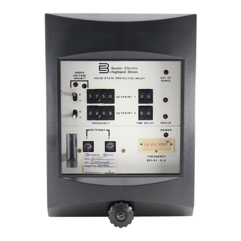
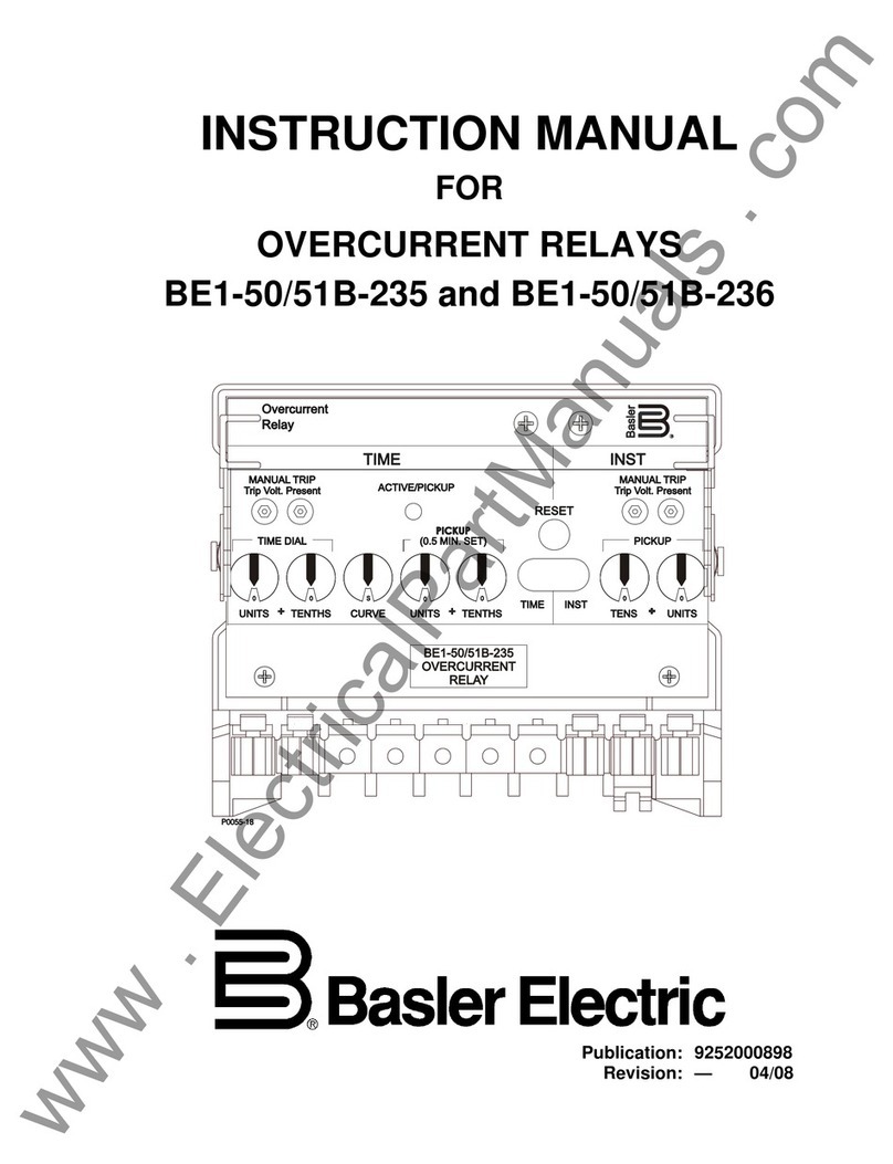
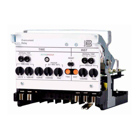
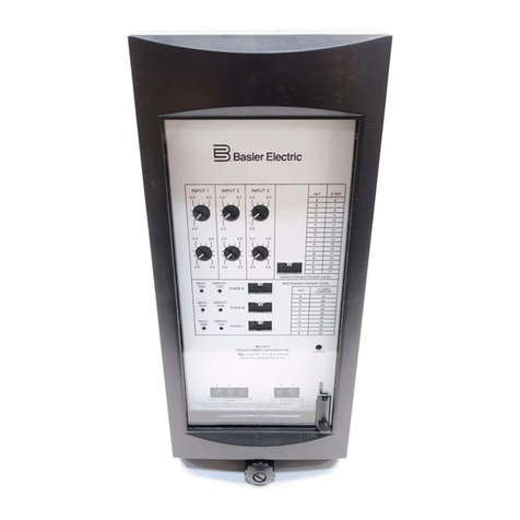
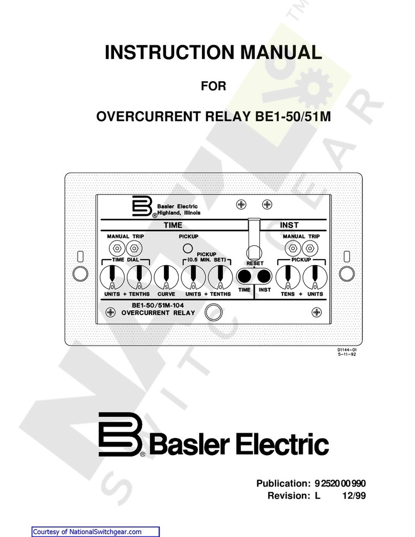
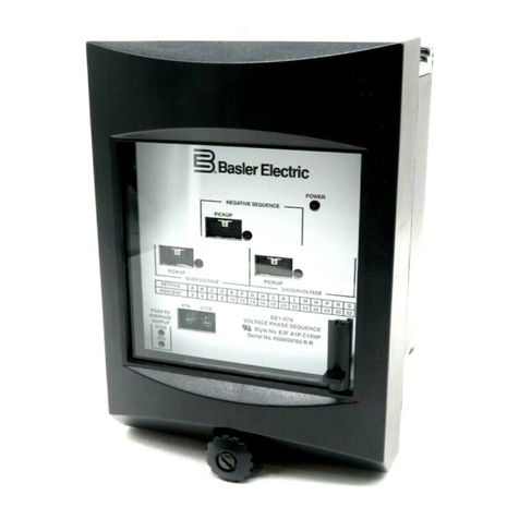
Basler BE1-81 User manual

+05647%6+10/#07#.
(14
&+)+6#.70&'4(4'37'0%;4'.#;
/1&'.$'
2WDNKECVKQ
4GXKUKQ $

i
W A R N I N G !
To avoid personal injury or equipment damage, only
qualified personnel should perform the procedures
presented in this manual.
INTRODUCTION
This Instruction Manual provides information concerning the
operationandinstallationoftheBE1-81DigitalUnderfrequencyRelay.
To accomplish this, the following is provided.
Specifications
Functional Characteristics
Mounting Information
Connections
Testing

ii
CONFIDENTIAL INFORMATION
OF BASLER ELECTRIC COMPANY, HIGHLAND, IL. IT IS LOANED FOR
CONFIDENTIAL USE, SUBJECT TO RETURN ON REQUEST, AND WITH THE
MUTUAL UNDERSTANDING THAT IT WILL NOT BE USED IN ANY MANNER
DETRIMENTAL TO THE INTEREST OF BASLER ELECTRIC COMPANY.
First Printing: October 1979
Printed in USA
© 1995, Basler Electric Co., Highland, IL 62249
May 1996
It is not the intention of this manual to cover all details and variations
in equipment, nor does this manual provide data for every possible
contingency regarding installation or operation. The availability and
design of all features and options are subject to modification without
notice. Should further information be required, contact Basler
Electric Company, Highland, Illinois.
BASLER ELECTRIC, BOX 269 HIGHLAND, IL 62249 USA
PHONE 618-654-2341 FAX 618-654-2351

iii
CONTENTS
SECTION 1 GENERAL INFORMATION 1-1
Purpose ...................................................... 1-1
Description .................................................... 1-1
Definite Time Option ......................................... 1-1
Inverse Time Option .......................................... 1-1
Relay Assembly ............................................. 1-1
Model and Style Number Description ................................ 1-1
Sample Style Number ........................................ 1-4
Style Number Identification Chart ............................... 1-4
Specifications .................................................. 1-5
SECTION 2 CONTROLS AND INDICATORS 2-1
SECTION 3 FUNCTIONAL DESCRIPTION 3-1
Functional Description ........................................... 3-1
Sensing ................................................... 3-1
Power Supply ............................................... 3-2
Power Supply Status Contacts .................................. 3-2
Voltage Inhibit Circuit ......................................... 3-2
Input Conditioning Circuit ...................................... 3-2
Crystal Reference Oscillator ................................... 3-2
Synchronizer Circuit .......................................... 3-3
Reference Circuit ............................................ 3-3
Period Difference Circuit ...................................... 3-3
Period Difference To Frequency Difference Circuit .................. 3-3
Threshold Setting Comparator .................................. 3-3
Definite Time Delay Circuit (Timing Option E1) ..................... 3-3
Inverse Time Delay Circuit (Timing Option D1) ..................... 3-3
Relay Output ............................................... 3-3
Internally Operated Target Driver ................................ 3-4
Current Operated Target Driver ................................. 3-4
Target Indicator ............................................. 3-4
SECTION 4 INSTALLATION 4-1
General ....................................................... 4-1
Relay Operating Precautions ...................................... 4-1
Dielectric Test .................................................. 4-1
Relay Mounting ................................................ 4-1
S1 Case, Panel Drilling Diagram, Semi-Flush Mounting .............. 4-2
S1 Case, Outline Dimensions, Front View ......................... 4-2
S1 Case, Single-Ended, Semi-Flush Mounting, Side View ............ 4-3
S1 Case, Single-Ended, Semi-Flush Mounting, Outline Dimensions ..... 4-4
S1 Case, Single-Ended, Projection Mounting, Panel Drilling Diagram .... 4-5
S1 Case, Single-Ended, Projection Mounting, Rear View ............. 4-6
S1 Case, Single-Ended, Projection Mounting, Side View ............. 4-7
S1 Case, Double-Ended, Semi-Flush Mounting, Side View ............ 4-8
S1 Case, Double-Ended, Semi-Flush Mounting, Outline Dimensions .... 4-9
iv
CONTENTS - Continued
SECTION 4 INSTALLATION - Continued
Relay Mounting - Continued
S1 Case, Double-Ended, Projection Mounting, Panel Drilling Diagram . . . 4-10
S1 Case, Double-Ended, Projection Mounting, Rear View .............4-11
S1 Case, Double-Ended, Projection Mounting, Side View .............4-12
Connections ...................................................4-13
AC Sensing Input Connections ..................................4-13
DC Control Connections .......................................4-14
Internal Connections, Style Number T?E ?1? A0S5? .................4-15
Internal Connections, Style Number T?E ?1C A2S5? ................4-16
SECTION 5 TESTING 5-1
General .......................................................5-1
Test Setup .....................................................5-1
Definite Time Delay (Option E1) Test Procedure .......................5-2
Inverse Time Delay (Option D1) Test Procedure .......................5-3
SECTION 6 MAINTENANCE 6-1
General .......................................................6-1
In-House Repair ................................................6-1
Storage .......................................................6-1
Test Plug ......................................................6-2
SECTION 7 Manual Change Information 7-1

1-1
SECTION 1
GENERAL INFORMATION
PURPOSE
BE1-81 Digital Underfrequency Relays are single-phase, solid-state, protective devices designed to
detect an underfrequency condition and provide an output to actuate external control circuits and/or
alarms. Both 50 hertz and 60 hertz styles are available with either definite time delay or inverse time
delay characteristics.
DESCRIPTION
BE1-81 relays compare the frequency of the applied voltage with a crystal oscillator reference frequency.
When the measured frequency is less than a preset level for a predetermined period of time, external
control circuits and/or alarms are actuated by the relay.
Definite Time Option
Definite time option trip frequency settings are set by three front panel thumbwheel switches. Setting
ranges are between 0.05 and 5.00 hertz in 0.05 hertz increments below nominal system frequency. The
delay time (measured in cycles of the underfrequency waveform) is set by two front panel thumbwheel
switches. Delay ranges are from 01 to 99 cycles. The actual trip time is the delay time setting, plus one
cycle.
Inverse Time Option
Inverse time option trip frequency settings are also set by three front panel thumbwheel switches and the
ranges are from 0.05 to 5.00 hertz in 0.05 hertz increments below nominal system frequency. The
inverse time delay characteristic is inversely proportional to the magnitude of the frequency difference
between the measured waveform and the trip frequency setting. This time may be adjusted to
correspond to a particular characteristic curve by a continuously adjustable front panel time dial. (Refer
to Figures 1-1 and 1-2.)
Relay Assembly
The relay assembly is mounted in a drawout cradle and enclosed in a standard, utility style, semi-flush
case. Individual circuit components are accessible by removal of the individual printed circuit boards
from the relay cradle and using an extender card (Basler part number 9 1655 00 100) to test or
troubleshoot. A front panel, electrically operated, manually reset target may be selected to indicate that a
fault has occurred and the relay has operated. A wide range of options permits the relay to be
specifically tailored to a variety of applications.
MODEL AND STYLE NUMBER DESCRIPTION
BE1-81 Digital Underfrequency Relays electrical characteristics and optional features are defined by a
combination of letters and numbers that make up its style number. The model number, together with the
style number, describe the options included in a specific device, and appear on the front panel, drawout
cradle, and inside the case assembly. Upon receipt of a relay, be sure to check its style number against
the requisition and packing list, to see that they agree.

BE1-81 General Information
1-2
Figure 1-1. Inverse Time Curves, 50 Hertz Option

BE1-81 General Information
1-3
Figure 1-2. Inverse Time Curves, 60 Hertz Option

BE1-81 General Information
1-4
Sample Style Number
Style number identification chart (Figure 1-3) defines the electrical characteristics and operational
features included in BE1-81 relays. For example, if the style number were T1E-E1C-A0N0F, the device
would have the following:
(T) Single phase sensing input type
(1) 120 Vac, 60 hertz nominal sensing input range
(E) One normally open relay output
(E1) Definite time delay
(C) Internal operating power obtained from 125 Vdc or 100/120 Vac - external source
(A) One internally operated target
(0) Internal relay operating power independent of sensed voltage
(N) No Option 2 available
(0) No auxiliary output
(F) Semi-flush mounting
Figure 1-3. Style Number Identification Chart

BE1-81 General Information
1-5
SPECIFICATIONS
Power Input One of the six types of power supplies listed in Table 1-1 may be optionally
selected to provide internal relay operating power.
Table 1-1. Power Supply Options
Frequency Sensing Input Input sensing circuits are nominally rated 120 Vac at the selected
frequency. Relay trip points may be manually set for a single-phase
underfrequency trip point from 45 to 50 hertz for the 50 hertz styles, or 55
to 60 hertz for the 60 hertz styles. Both styles are adjustable in 0.05 hertz
increments.
Sensing Burden Burden of the frequency sensing input is 2 VA for 50 hertz styles, and 1 VA
for 60 hertz styles.
Target Indicators Function targets may be specified as either internally operated, or current
operatedbyaminimumof0.2ampere throughtheoutputtripcircuit. When
current operated, the output circuit must be limited to 30 amperes for 0.2
seconds,7 amperes for2 minutes,and 3amperescontinuously. Internally
operated targets must be specified if the breaker control (trip) circuit is ac
powered.
Reset Time Reset is automatic and instantaneous when frequency increases above
selected pickup setting. (Target must be manually reset.)
Pickup Setting Pickup setting is adjusted in Hertz-below-nominal-frequency in 0.05 hertz
steps, using three front panel thumbwheel switches.
Pickup Accuracy The relay will pickup and check timing within 0.030 hertz of the trip point in
a 60 hertz system, and within 0.035 hertz in a 50 hertz system.

BE1-81 General Information
1-6
Dropout Ratio 99 percent of pickup value (frequency difference).
Temperature Stability Pickup point variation will not exceed 0.03 hertz over the operating
temperature range.
Undervoltage Inhibit The relay is factory adjusted for an 80 Vac undervoltage inhibit level that
preventsnuisance tripping during protected equipment start-up. This level
may be internally adjusted by the user for inhibit levels between 40 and
120 Vac except for relays using option 1-2, Sensing Input Power Supply.
Output Circuits Output contacts are rated as follows:
Resistive:
120/240 Vac Make 30 amperes for 0.2 seconds, carry 7 amperes continuously, and
break 7 amperes.
250 Vdc Make and carry 30 amperes for 0.2 seconds, carry 7 amperes
continuously, and break 0.3 amperes.
500 Vdc Make and carry 15 amperes for 0.2 seconds, carry 7 amperes
continuously, and break 0.1 amperes.
Inductive:
120/240Vac, Makeandcarry30amperesfor0.2seconds,carry7amperes continuously,
125/250 Vdc and break 0.3 amperes. (L/R = 0.04).
Isolation 1500 Vac at 60 hertz for one minute in accordance with IEC 255-5 and
ANSI/IEEE C37.90-1989 (Dielectric Test).
RadioFrequency Maintainsproperoperationwhentestedforinterferenceinaccordance with
Interference(RFI) ANSI/IEEEC37.90-1989,
Trial-UseStandardWithstandCapabilityof Relay
Systems to Radiated Electromagnetic Interference from Transceivers.
UL Recognized UL Recognized per Standard 508, UL File No. E97033. Note: Output
contacts are not UL Recognized for voltages greater than 250 volts.
SurgeWithstandCapability QualifiedtoANSI/IEEEC37.90.1-1989
StandardSurge Withstand Capabil-
ity (SWC) Tests for Protective Relays and Relay Systems.
Operating Temperature -20C (-4F) to +65C (+149F).
Storage Temperature -50C (-58F) to +90C (+194F).
Shock In standard tests, the relay has withstood 15 g in each of three mutually
perpendicular planes without structural damage or degradation of perfor-
mance.
Vibration In standard tests, the relay has withstood 2 g in each of three mutually per-
pendicular planes, swept over the range of 10 to 500 Hz for a total of six
sweeps,15minuteseachsweep,withoutstructuraldamageordegradation
of performance.
Weight 10.5 pounds net.
Case Size S1. Dimensions shown in Section 4,
Installation
.

2-1
SECTION 2
CONTROLS AND INDICATORS
GENERAL
Table 2-1 lists and describes the controls and indicators of BE1-81 Digital Underfrequency Relays.
Table 2-1. Controls and Indicators (Refer to Figures 2-1 and 2-2)
Letter Control or Indicator Function or Indicator
A DELAY CYCLES switches
(Option E1 only) Two thumbwheel switches set the time delay (measured
in cycles of the underfrequency waveform. The time
delay range is from 01 to 99 cycles. False tripping may
occur if the delay is set below 3 cycles. Also, the relay will
not function if these switches are set at 00.
B POWER LED LED lights to indicate that the relay power supply is
functioning.
C TRIP FREQUENCY HZ
BELOW 60 HZ switches Three thumbwheel switches set the trip frequency in
increments of 0.05 hertz, between 45 and 50 hertz
(50 hertz styles) or 55 and 60 hertz (60 hertz styles). The
switch settings then display the frequency (in hertz) below
the nominal system frequency at which the relay trip
threshold is set.
DTarget Reset Lever Linkage extending through bottom of front cover that
resets magnetically latching target indicators.
ETarget Indicator Magnetically latching target that indicates that trip current in
excess of 0.2 amperes was present and that the associated
output relay has been energized.
F TRIP TIME ADJUST Control
(Option D1 only) Control selects the desired inverse characteristic trip
curve.

BE1-81 Controls And Indicators
2-2
Figure 2-1. Location Of Controls And Indicators (Option E1)

BE1-81 Controls And Indicators
2-3
Figure 2-2. Location Of Controls And Indicators (Option D1)

BE1-81 Controls And Indicators
2-4
Figure 2-3. Location Of Assemblies

3-1
SECTION 3
FUNCTIONAL DESCRIPTION
Functional circuit descriptions provided in this section apply to both the 50 hertz and 60 hertz
underfrequency relays. Refer to Figure 3-1 for a typical functional block diagram.
Sensing
When single-phase 120 Vac is applied to the sensing input, the input transformer provides the proper
signal levels to the voltage inhibit and input conditioning circuits.
Figure 3-1. Functional Block Diagram

BE1-81 Functional Description
3-2
Power Supply
A variety of power supply options allow a wide range of external voltage inputs for relay operation.
Relay operating power is developed by the low burden, flyback switching design, solid-state power
supply. A nominal plus or minus twelve volts dc is delivered to the internal circuitry. Power supply
inputs are not polarity sensitive. A red LED lights to indicate that the power supply is functioning
properly. The LED circuit is not provided on styles receiving operating power from the sensing input.
Type W power supplies use a field adjustable link (J4) to select the appropriate input voltage (either 48
Vdc or 125 Vdc). Selection is accomplished by placing the link into the desired position (refer to Figure
3-2). This link is factory pre-set for 125 Vdc.
Figure 3-2. J4 Link Positioning
Power Supply Status Contacts
Power supply voltages are monitored on the mother board. Normal supply voltage causes the power
supply status relay to be continually energized. However, if at any time the voltage falls below
requirements, the relay drops out, and closes the normally closed contacts.
Voltage Inhibit Circuit
This circuit prevents the relay from tripping because of transient underfrequency conditions associated
with equipment startup. It inhibits sensing of underfrequency conditions by the synchronizer circuit and
output circuitry until the input sensing voltage is greater than 80 Vac.
Input Conditioning Circuit
The input conditioning circuit converts the sensing voltage to a squarewave whose transitions
correspond to the zero crossings of the input waveform. The resulting squarewave (after further
shaping) is applied to the synchronizer circuit.
Crystal Reference Oscillator
This four megahertz, crystal-controlled oscillator provides an accurate reference for the synchronizer
circuit and the frequency reference circuit.

BE1-81 Functional Description
3-3
Synchronizer Circuit
This circuit synchronizes the squarewave (representative of the input waveform) with the crystal
reference oscillator to generate a synchronized zero crossing pulse. The zero crossing pulse resets the
system timing. Each time this zero crossing pulse occurs, a new frequency comparison is initiated.
Reference Circuit
This circuit generates a reference signal each 16.667 millisecond (60 hertz nominal system frequency)
or 20.000 ms (50 hertz nominal system frequency) after a synchronized zero crossing pulse. This signal
is generated by counting pulses from the reference oscillator. When the proper count is reached, an
output signal is applied to the period difference circuit.
Period Difference Circuit
This circuit initiates a train of pulses beginning with the occurrence of the reference signal and ending
when the synchronized zero crossing pulse occurs. The time span between these two signals is the
difference in period between the sensing input waveform and the nominal system frequency. Each pulse
in the pulse train represents a one microsecond difference in period.
Period Difference To Frequency Difference Circuit
This circuit converts the pulses received from the period difference circuit to one pulse for each 0.05
hertz difference from the nominal frequency. This is accomplished by a variable scale divider which
compensates for the inverse relationship between period and frequency.
Threshold Setting Comparator
This circuit counts the number of pulses coming from the frequency difference circuit and compares it
with the front panel control setting. When the frequency decreases beyond the difference established by
the front control, an output pulse is applied to the appropriate timing circuit.
Definite Time Delay Circuit (Timing Option E1)
The definite time delay circuit counts the number of consecutive cycles of the underfrequency waveform
after the threshold setting comparator output pulse occurs. When the number of underfrequency cycles
equals the front panel time delay setting, a pulse is generated to the output trip circuit. It is
recommended that the time delay control be set for a minimum of three cycles delay to reduce the
possibility of a trip signal caused by transient-generated underfrequency conditions.
Inverse Time Delay Circuit (Timing Option D1)
The inverse time delay circuit uses the magnitude of the underfrequency condition to determine the time
delay. A set of pulses, representative of the magnitude of the underfrequency condition, is applied to an
RC network to generate an inverse time delay. A front panel dial permits adjustment of the time curve
over the applicable 60 hertz or 50 hertz system range. An LED on the front panel indicates that the relay
pickup setting has been exceeded.
Relay Output
Either normally closed or normally open relay output contacts may be selected. An optional set of
auxiliary relay contacts may be specified when the relay auxiliary output option is selected. The relay
contacts remain in the energized condition as long as the sensed input is below pickup.

BE1-81 Functional Description
3-4
Internally Operated Target Driver
Output from the time delay circuit is applied to this circuit to drive the target indicator. The indicator is
tripped regardless of the current level in the trip circuit.
Current Operated Target Driver
This circuit will operate when a minimum dc current of 0.2 amperes flow in the output trip circuit. A
special reed relay in series with the output contact provides the signal to the target indicator.
Target Indicator
The target trip indicator is visible at the front panel. The target is magnetically latched and must be reset
manually after the fault condition has been cleared.

4-1
SECTION 4
INSTALLATION
GENERAL
When not shipped as part of a control or switchgear panel, the relays are shipped in sturdy cartons to
prevent damage during transit. Immediately upon receipt of a relay, check the model and style number
against the requisition and packing list to see that they agree. Visually inspect the relay for damage that
may have occurred during shipment. If there is evidence of damage, immediately file a claim with the
carrier and notify the Regional Sales Office, or contact the Sales Representative at Basler Electric,
Highland, Illinois.
In the event the relay is not to be installed immediately, store the relay in its original shipping carton in a
moisture and dust-free environment. When relay is to be placed in service, it is recommended that the
operational test procedure (Section 5) be performed prior to installation.
RELAY OPERATING PRECAUTIONS
Before installation or operation of the relay, note the following precautions:
1. A minimum of 0.2 A in the output circuit is required to ensure operation of current operated
targets.
2. Do not touch target indicator vanes. Always reset targets by use of the target reset lever.
3. The relay is a solid-state device. If a wiring insulation test is required, remove the connecting
plugs and withdraw the cradle from its case.
4. When the connecting plugs are removed, the relay is disconnected from the operating circuit and
will not provide system protection. Always be sure that external operating (monitored) conditions
are stable before removing a relay for inspection, test, or service.
5. Be sure the relay case is hard wired to earth ground using the ground terminal on the rear of the
unit. It is recommended to use a separate ground lead to the ground bus for each relay.
DIELECTRIC TEST
In accordance with IEC 255-5 and ANSI/IEEE C37.90-1978, one-minute dielectric (high potential) tests
up to 1500 Vac (45-65 hertz) may be performed. This device employs decoupling capacitors to ground
from terminals 3 and 4. Accordingly, a leakage current is to be expected at these terminals.
RELAY MOUNTING
Because the relay is of solid state design, it does not have to be mounted vertically. Any convenient
mounting angle may be chosen. Figures 4-1 through 4-12 provide relay outline dimensions and panel
drilling diagrams.
Table of contents
Other Basler Relay manuals

Basler
Basler BE1-49 User manual

Basler
Basler BE1-DFPR User manual

Basler
Basler BE1-59N User manual

Basler
Basler BE1-50/51B-217 User manual

Basler
Basler BE1-46N User manual

Basler
Basler V3E Z1P B2C1F User manual

Basler
Basler BE1-87B User manual

Basler
Basler BE1-50BF User manual

Basler
Basler BE1-51B User manual

Basler
Basler BE1-59NC User manual

Basler
Basler BE1-27 User manual

Basler
Basler BE1-25 User manual

Basler
Basler BE1-47N User manual

Basler
Basler Class 300 User manual

Basler
Basler BE1-27 User manual

Basler
Basler BE1-50/51M-100 Series User manual

Basler
Basler BE1-79 User manual

Basler
Basler BE1-87G User manual

Basler
Basler BE1-951 User manual

Basler
Basler BE1-11g User manual