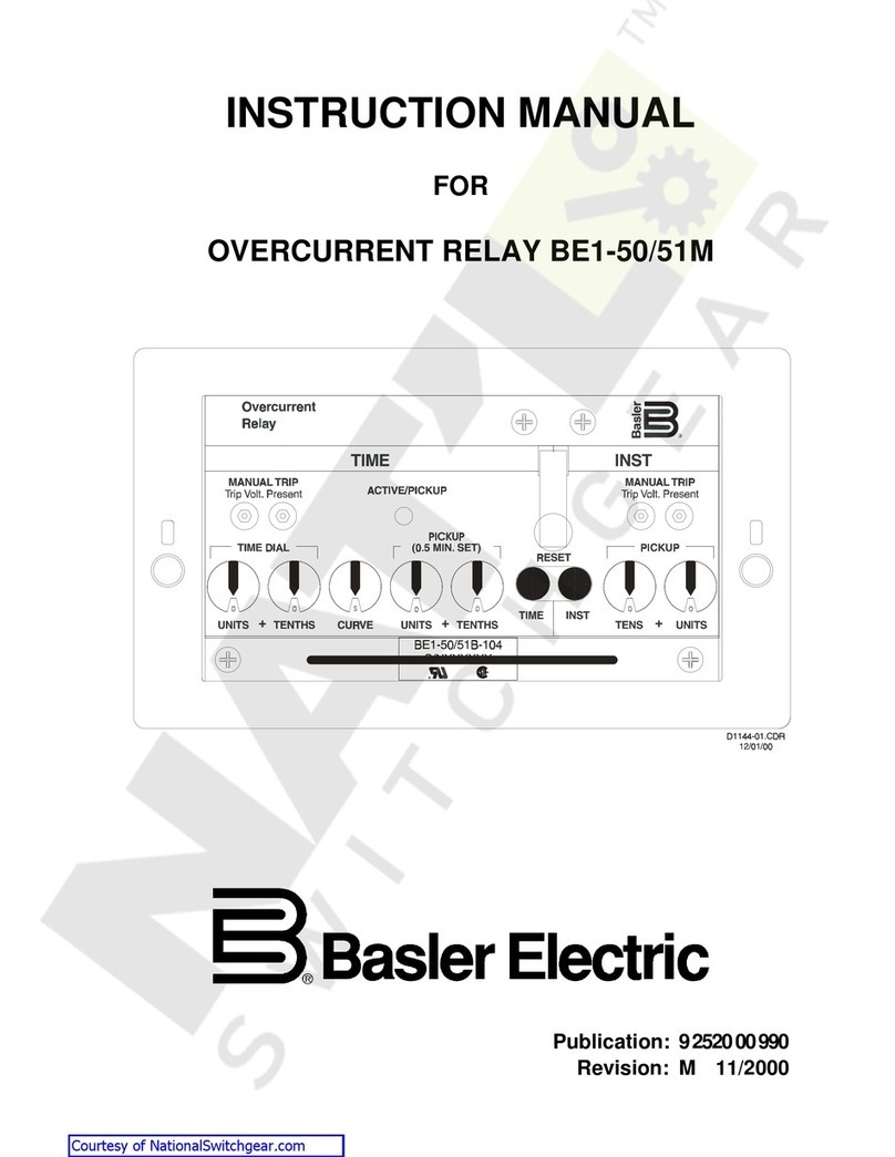
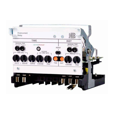
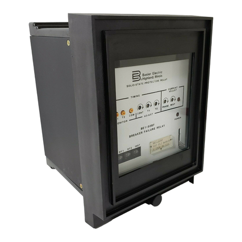
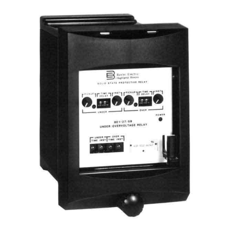
Basler BE1-59N User manual

INTRODUCTION
The
purpose
of
this
instruction
Manual
is
to
furnish
information
concerning
the
operation
and
installation
of
this
device
,
accomplish
this
,
the
following
is
provided
.
To
Specifications
Functional
characteristics
Operational
Tests
Mounting
Information
t
WAR
NiNG
!
To
avoid
personal
injury
or
equipment
damage
,
only
qualified
personnel
should
perform
the
procedures
presented
in
this
manual
.
REV
A
B
C
D
ECA
9248
10222
11591
13079
I
Courtesy of NationalSwitchgear.com

First
Printing
:
November
1986
Printed
in
USA
January
1993
CONFIDENTIAL
INFORMATION
OF
BASLER
ELECTRIC
COMPANY
,
HIGHLAND
,
IL
.
IT
IS
LOANED
FOR
CONFIDENTIAL
USE
,
SUBJECT
TO
RETURN
ON
REQUEST
,
AND
WITH
THE
MUTUAL
UNDERSTANDING
THAT
IT
WILL
NOT
BE
USED
IN
ANY
MANNER
DETRIMENTAL
TO
THE
INTEREST
OF
BASLER
ELECTRIC
COMPANY
.
it
is
not
the
intention
of
this
manual
to
cover
all
details
and
variations
in
equipment
,
nor
does
this
manual
provide
data
for
every
possible
contingency
regarding
installation
or
operation
.
The
availability
and
design
of
all
features
and
options
are
subject
to
modification
without
notice
.
Should
further
information
be
required
,
contact
Basler
Electric
Company
,
Highland
,
Illinois
.
BASLER
ELECTRIC
,
BOX
269
HIGHLAND
,
IL
62249
USA
PHONE
618
-
654
-
2341
FAX
618
-
654
-
2351
•
•
II
Courtesy of NationalSwitchgear.com

CONTENTS
1
-
1
GENERAL
INFORMATION
Section
1
1
-
1
Description
High
Resistance
Grounding
Ungrounded
Systems
Model
and
Style
Number
Sample
Style
Number
Style
Number
Identification
Chart
Specifications
Inverse
Time
Curves
1
-
1
1
-
1
1
-
2
1
-
2
1
-
3
1
-
4
1
-
6
CONTROLS
AND
INDICATORS
2
-
1
Section
2
FUNCTIONAL
DESCRIPTION
3
-
1
Section
3
General
Inputs
Filters
Overvoltage
Comparator
Definite
Time
Delay
(
Optional
)
.
Inverse
Time
Delay
(
Optional
)
.
Reference
voltage
Circuit
..
.
.
Undervoltage
element
(
Optional
)
Undervoltage
Operation
.
.
Undervoltage
Inhibit
Power
Supply
Power
Supply
Status
Contacts
Target
Indicator
Circuits
Internally
Operated
Targets
Current
Operated
3
-
1
3
-
1
3
-
1
3
-
1
3
-
1
3
-
2
3
-
2
3
-
2
3
-
2
3
-
2
3
-
3
3
-
3
3
-
3
3
-
3
3
-
3
INSTALLATION
Section
4
4
-
1
General
Relay
Operating
Precautions
Mounting
Connections
Operational
Test
4
-
1
4
-
1
4
-
1
4
-
1
4
-
5
Section
5
MAINTENANCE
5
-
1
General
In
-
House
Repair
Storage
Test
Plug
5
-
1
5
-
1
5
-
1
5
-
2
MANUAL
CHANGE
INFORMATION
Section
6
6
-
1
•
••
III
Courtesy of NationalSwitchgear.com

SECTION
1
GENERAL
INFORMATION
r
DESCRIPTION
The
available
fault
current
for
single
-
phase
-
to
-
ground
faults
is
very
limited
for
ungrounded
systems
and
systems
which
are
grounded
through
a
high
resistance
.
This
current
limiting
reduces
the
possibility
of
extensive
equipment
damage
,
and
eliminates
the
need
for
a
neutral
breaker
by
reducing
the
fault
current
below
the
level
required
to
sustain
an
arc
.
But
,
it
remains
important
to
detect
and
isolate
single
-
phase
-
to
-
ground
faults
in
order
to
prevent
their
evolution
into
more
dangerous
faults
such
as
phase
-
to
-
phase
-
to
-
ground
and
three
-
phase
-
to
-
ground
faults
.
Sensitive
voltage
relays
can
be
used
to
detect
ground
faults
where
the
fault
current
is
very
small
.
The
BE
1
-
59
N
Ground
Fault
Overvoltage
Relay
is
especially
suited
to
this
task
.
HIGH
RESISTANCE
GROUNDING
A
common
method
of
grounding
an
ac
generator
is
to
connect
a
distribution
transformer
between
the
neutral
of
the
generator
and
the
station
ground
.
The
distribution
transformer
’
s
primary
voltage
rating
is
equal
to
,
or
greater
than
,
the
generator
’
s
rated
line
-
to
-
neutral
voltage
.
The
distribution
transformer
secondary
is
rated
at
200
/
240
Vac
or
100
/
120
Vac
,
and
a
resistor
is
connected
across
the
secondary
winding
.
When
reflected
through
the
transformer
,
the
resistor
is
effectively
a
high
resistance
.
Rp
=
Rs
x
N
2
where
Rp
is
the
effective
primary
resistance
Rs
is
the
actual
value
of
the
secondary
resistor
N
is
the
turns
ratio
of
the
distribution
transformer
Available
single
-
phase
-
to
-
ground
fault
current
at
the
generator
terminals
is
greatly
reduced
by
the
high
effective
resistance
of
the
distribution
transformer
and
secondary
resistor
.
The
distribution
transformer
provides
isolation
for
the
protection
scheme
and
reduces
the
voltage
to
a
convenient
level
.
The
BE
1
-
59
N
Ground
Fault
Overvoltage
Relay
is
connected
across
the
secondary
resistor
to
detect
the
increase
in
voltage
across
the
distribution
transformer
caused
by
a
ground
fault
in
the
generator
stator
windings
.
A
ground
fault
at
the
generator
terminals
will
result
in
rated
line
-
to
-
neutral
voltage
across
the
transformer
primary
,
while
ground
faults
near
the
neutral
will
result
in
lower
voltages
.
The
overvoltage
relay
setpoint
must
be
higher
than
any
neutral
voltage
caused
by
normal
unbalances
in
order
to
avoid
nuisance
trips
.
This
will
allow
a
certain
percentage
of
the
stator
windings
to
go
unprotected
by
the
overvoltage
relay
.
The
overvoltage
relay
function
typically
protects
90
to
95
%
of
the
generator
stator
windings
.
The
BE
1
-
59
N
Ground
Fault
Overvoltage
Relay
monitors
the
fundamental
frequency
(
50
or
60
Hz
)
voltage
which
accompanies
a
ground
fault
,
but
is
insensitive
to
the
third
harmonic
voltage
present
during
normal
operation
.
One
hundred
percent
protection
of
the
generator
stator
windings
is
obtainable
with
the
optional
overlapping
undervoltage
element
.
The
under
voltage
element
is
tuned
to
the
third
harmonic
voltage
which
is
present
in
the
generator
neutral
under
normal
conditions
.
The
undervoltage
element
detects
the
reduction
of
the
normal
third
harmonic
voltage
which
accompanies
a
ground
fault
near
the
neutral
point
of
the
generator
.
An
undervoltage
inhibit
feature
is
included
with
the
third
harmonic
undervoltage
element
.
This
feature
supervises
the
operation
of
the
ground
fault
relay
to
prevent
operation
during
startup
and
shutdown
by
monitoring
the
generator
terminal
voltage
.
UNGROUNDED
SYSTEMS
The
BE
1
-
59
N
Ground
Fault
Overvoltage
Relay
is
used
to
detect
ground
faults
on
ungrounded
three
-
phase
-
three
-
wire
systems
.
The
relay
is
connected
as
shown
in
Figure
1
-
1
.
A
set
of
voltage
transformers
are
wired
1
-
1
Courtesy of NationalSwitchgear.com

BE
1
-
59
N
General
Information
with
a
grounded
wye
primary
and
a
broken
delta
secondary
.
The
BEI
-
59
N
is
connected
across
the
broken
delta
.
It
is
often
necessary
to
connect
a
resistor
across
the
broken
delta
to
avoid
ferroresonance
.
Grounded
wye
/
broken
delta
voltage
transformers
act
as
a
zero
sequence
filters
by
summing
the
three
phase
voltages
.
Under
normal
conditions
this
sum
is
zero
.
When
a
ground
fault
occurs
,
the
BE
1
-
59
N
Ground
Fault
Overvoltage
Relay
will
detect
the
presence
of
the
secondary
zero
sequence
voltage
(
3
Vo
)
~
1
The
BE
1
-
59
N
Ground
Fault
Overvoltage
Relay
greatly
reduces
the
risk
of
equipment
damage
by
detecting
and
isolating
the
first
ground
on
an
ungrounded
system
.
A
B
LOAD
52
SOURCE
C
JUJ
JUJ
JUJ
1
PT
59
N
Figure
1
-
1
.
Ungrounded
3
-
Phase
,
3
-
Wire
System
MODEL
AND
STYLE
NUMBER
Electrical
characteristics
and
operational
features
included
in
a
specific
relay
are
defined
by
a
combination
of
letters
and
numbers
which
makes
up
the
device
style
number
.
The
model
number
,
BE
1
-
59
N
,
designates
the
device
as
a
Basler
Electric
Class
100
Ground
Fault
Overvoltage
protective
relay
.
The
style
number
together
with
the
model
number
describe
the
features
and
options
in
a
particular
device
and
appear
on
the
front
panel
,
drawout
cradle
and
inside
the
case
assembly
.
Sample
Style
Number
In
Figure
1
-
2
,
the
style
number
identification
chart
illustrates
the
features
of
a
relay
sample
style
number
.
If
the
style
number
were
A
5
FF
6
J
D
2
S
3
F
,
the
relay
would
have
the
following
features
:
Model
Number
Single
-
phase
voltage
sensing
input
120
Vac
,
60
hertz
sensing
input
(
nominal
)
with
1
to
20
Vac
pickup
range
Two
normally
-
open
output
relays
(
one
overvoltage
and
one
undervoltage
)
Inverse
time
delay
for
overvoltage
and
definite
time
delay
for
undervoltage
Operating
power
derived
from
either
125
Vdc
or
100
/
120
Vac
Two
current
operated
targets
(
one
per
function
)
Undervoltage
element
range
0.1
to
2.5
Vac
(
low
range
with
sensing
input
5
)
Push
-
to
-
energize
outputs
Two
auxiliary
output
relays
,
normally
-
open
(
one
per
function
)
Semi
-
flush
mounting
BE
1
-
59
N
A
5
F
F
6
J
D
2
S
3
F
1
-
2
Courtesy of NationalSwitchgear.com

1
son
-
-
BE
1
-
59
N
MOO
EL
NO
.
POWER
SUPPLY
SENSING
INPUT
TYPE
OPTION
1
OUTPUT
OPTION
3
TIMING
J
)
125
Vdc
and
100
/
120
Vac
K
)
4
&
Vdc
L
)
24
Vdc
Y
)
Selectable
48
/
125
Vdc
Z
)
250
Vdc
and
230
Vac
A
)
Single
-
phase
voltage
E
)
One
NO
relay
-
over
A
1
)
Over
—
Instantaneous
0
)
None
1
)
Undervoltage
element
—
A
high
range
-
/
4
\
0.5
to
12
Vac
0
)
None
1
)
One
NO
auxiliary
output
—
over
2
)
One
NC
auxiliary
output
—
over
3
)
Two
NO
auxiliary
A
oulpuU
-
/
*
\
one
under
4
)
Two
NC
auxiliary
A
outputs
—
/
2
\
one
under
01
)
Over
-
InverBe
El
)
Over
-
definite
(
0.1
-
99.9
sec
.
)
FI
)
Over
-
Instantaneous
A
!
F
2
)
Over
-
Instantaneous
under
—
Inverse
F
3
)
Over
-
definite
(
0.1
-
99.9
sec
.
)
under
—
Instantaneous
F
4
)
Over
-
definite
A
.
(
0.1
-
99.9
sec
.
)
/
?
\
under
—
Inverse
F
)
Two
NO
relays
-
A
one
over
,
/
2
\
one
under
G
)
One
NC
relay
-
over
<
Q
*
C
CD
00
A
m
ro
1.0
to
24
Vac
under
—
definite
0.1
—
99.9
sec
.
)
SENSING
INPUT
RANGE
Ol
2
)
Undervoltage
element
-
low
ran
0.1
to
Co
one
over
.
H
)
Two
NC
relays
-
one
over
,
one
under
CO
A
ct
>
A
ge
—
2.5
Voc
o
1
)
100
Vac
,
50
Hz
.
nominal
1
—
20
Vac
pickup
2
)
100
Vac
,
50
Hz
.
nominal
10
—
50
Vac
pickup
3
)
200
Vac
,
50
Hz
,
nominal
2
—
40
Vac
pickup
4
)
200
Vac
.
50
Hz
,
nominal
20
—
100
Voc
pickup
5
)
120
Vac
,
BO
Hz
,
nominal
1
-
20
Vac
pickup
6
)
120
Vac
,
60
Hz
,
nominal
10
-
50
Vac
pickup
7
)
240
Vac
.
60
Hz
,
nominal
2
-
40
Vac
pickup
8
)
240
Vac
.
60
Hz
,
nominal
20
—
100
Vac
pickup
CD
one
over
.
c
:
A
3
0.2
to
5.0
Vac
(
9
A
i
CT
DO
CJ
CD
Q
.
CD
O
A
TARGET
13
3
00
OPTION
4
O
F
5
)
Over
-
Inverse
un
der
-
Instan
tan
eous
OPTION
2
Q
)
O
N
)
None
C
)
Internally
operated
D
)
Current
operated
A
o
’
3
F
)
Semi
-
flush
mounting
P
)
Projection
mounting
F
6
)
Over
-
Inverse
A
under
-
deflnlte
(
0.1
-
99.9
sec
.
)
F
7
)
Over
—
definite
under
-
deflnlte
N
)
None
S
)
Push
-
to
-
energtze
outputs
O
Q
>
A
NOTES
;
3
)
All
relays
are
supplied
In
SI
case
.
Senelng
Input
range
1
.
2
,
5
.
or
6
.
Sensing
Input
3
,
4
,
7
,
or
8
.
When
target
Is
D
,
output
must
be
E
or
A
F
.
Requires
option
1
-
1
option
1
-
2
.
A
or
DS
11
-
004
4
-
26
-
02
range
Courtesy of NationalSwitchgear.com

BE
1
-
59
N
General
Information
SPECIFICATIONS
The
BE
1
-
59
N
Ground
Fault
Overvoltage
Relay
has
the
following
features
and
capabilities
.
A
Maximum
continuous
rating
:
360
Vac
for
100
/
120
Vac
input
,
480
Vac
for
200
/
240
Vac
input
,
with
a
maximum
burden
of
2
VA
for
each
input
.
Voltage
Sensing
inputs
High
range
:
0.5
to
12
Vac
(
sensing
input
range
1
,
2
,
5
,
or
6
)
or
1.0
to
24
Vac
(
Sensing
input
range
3
,
4
,
7
,
or
8
)
.
Low
range
:
0.1
to
2.5
Vac
(
sensing
input
range
1
,
2
,
5
,
or
6
)
or
0.2
to
5.0
Vac
(
Sensing
input
range
3
,
4
,
7
,
or
8
)
.
Undervoltage
Sensing
Input
Range
120
Vac
(
sensing
input
range
1
,
2
,
5
,
or
6
)
±
2.0
%
or
100
millivolts
,
whichever
is
greater
.
Pickup
Accuracy
240
Vac
(
sensing
input
range
3
,
4
,
7
,
or
8
)
±
2.0
%
or
200
millivolts
,
whichever
is
greater
.
98
%
of
pickup
within
7
cycles
.
Dropout
Timing
Characteristics
Less
than
70
milliseconds
for
a
voltage
level
that
exceeds
the
pickup
setting
by
5
%
or
1
volt
(
whichever
is
greater
)
.
Instantaneous
(
no
intentional
delay
)
Adjustable
from
00.1
to
99.9
seconds
,
in
steps
of
0.1
seconds
.
Accuracy
is
within
2.0
%
or
100
milliseconds
,
whichever
is
greater
.
(
A
setting
of
00.0
provides
instantaneous
timing
.
)
Definite
4
Response
time
decreases
as
the
difference
between
the
monitored
voltage
and
the
setpoint
increases
.
The
inverse
time
characteristics
switch
is
adjustable
from
01
to
99
in
01
increments
.
Each
position
corresponds
to
a
specific
curve
except
00
,
which
is
instantaneous
.
Inverse
Accuracy
is
within
±
5
%
or
25.0
milliseconds
(
whichever
is
greater
)
of
the
indicated
time
for
any
combination
of
the
time
dial
and
within
±
2
%
of
the
voltage
magnitude
or
100
millivolts
(
for
the
120
Vac
sensing
range
)
or
200
millivolts
(
for
the
240
Vac
sensing
range
)
(
whichever
is
greater
)
from
the
actual
pickup
value
.
Inverse
time
is
repeatable
within
±
2
%
or
25.0
milliseconds
(
whichever
is
greater
)
for
any
time
dial
or
pickup
setting
.
The
characteristic
curves
are
defined
by
Figure
1
-
2
.
Output
contacts
are
rated
as
follows
:
Output
Contacts
Resistive
:
120
/
240
Vac
Make
30
A
for
0.2
seconds
,
carry
7
A
continuously
,
and
break
7
A
.
Make
and
carry
30
A
for
0.2
seconds
,
carry
7
A
continuously
,
and
break
0.1
A
.
250
Vdc
500
Vdc
Make
and
carry
15
A
for
0.2
seconds
,
carry
7
A
continuously
,
and
break
0.1
A
.
1
1
-
4
Courtesy of NationalSwitchgear.com

BE
1
-
59
N
General
Information
Output
Contacts
-
Continued
Inductive
:
120
/
240
Vac
,
Make
and
carry
30
A
for
0.2
seconds
,
carry
7
A
125
/
250
Vdc
continuously
,
and
break
0.1
A
.
(
L
/
R
=
0.04
)
.
Function
targets
may
be
specified
as
either
internally
operated
,
or
current
operated
by
a
minimum
of
0.2
A
through
the
output
trip
circuit
.
When
cur
-
rent
operated
,
the
output
circuit
must
be
limited
to
30
A
for
0.2
seconds
,
7
A
for
2
minutes
,
and
3
A
continuously
.
Target
Indicators
Input
power
may
be
obtained
from
a
variety
of
ac
or
dc
external
power
sources
.
Available
power
supply
options
are
indicated
in
Table
1
-
1
.
Power
Supply
Table
1
-
1
.
Power
Supply
Specifications
.
Nominal
Input
Voltage
Input
Voltage
Range
Burden
Type
at
Nominal
24
to
60
Vdc
48
Vdc
7.0
W
K
125
Vdc
120
Vac
62
to
150
Vdc
90
to
132
Vac
7.5
W
15.0
W
J
24
Vdc
12
to
32
Vdc
7.5
W
tL
24
to
60
VdC
62
to
150
Vdc
48
Vdc
125
Vdc
7.0
W
7.5
W
$
Y
140
to
280
Vdc
190
to
270
Vac
12.0
W
33.5
VA
2
250
Vdc
230
Vac
NOTES
:
t
Type
L
Power
Supply
may
require
14
Vdc
to
begin
operation
.
Once
operating
,
the
voltage
may
be
reduced
to
12
Vdc
.
t
Type
Y
Power
Supply
is
field
selectable
for
48
or
125
Vdc
.
Selection
must
be
implemented
at
time
of
installation
.
This
Power
Supply
option
is
factory
set
for
125
Vdc
.
1500
Vac
at
60
hertz
for
one
minute
in
accordance
with
I
EC
255
-
5
and
ANSI
/
IEEE
C
37.90
-
1989
(
Dielectric
Test
)
.
Isolation
Field
Tested
using
a
five
watt
,
hand
-
held
transceiver
operating
at
random
frequencies
centered
around
144
MHz
and
440
MHz
,
with
the
antenna
located
six
inches
from
the
relay
in
both
horizontal
and
vertical
planes
.
Radio
Frequency
Interference
(
RFI
)
Surge
Withstand
Capability
Qualified
to
ANSI
/
IEEE
C
37.90
.
1
-
1989
Standard
Surge
Withstand
Capability
(
SWC
)
Tests
for
Protective
Relays
and
Relay
Systems
.
-
40
°
C
(
-
40
°
F
)
to
+
70
°
C
(
+
158
°
F
)
.
Operating
Temperature
-
65
°
C
(
-
85
°
F
)
to
+
100
°
C
(
+
212
°
F
)
.
Storage
Temperature
In
standard
tests
,
the
relay
has
withstood
15
g
in
each
of
three
mutually
perpendicular
planes
without
structural
damage
or
degradation
of
perfor
-
mance
.
Shock
1
-
5
Courtesy of NationalSwitchgear.com

BE
1
-
59
N
General
Information
In
standard
tests
,
the
relay
has
withstood
2
g
in
«
chof
three
Dendicular
planes
,
swept
over
the
range
of
10
to
500
Hz
for
ai
total
w
s
sweeps
.
15
minutes
each
sweep
,
without
structural
damage
or
degradation
of
performance
.
Vibration
:
1
13.6
maximum
.
Weight
S
1
.
Case
Size
40
JO
30.0
20.0
10
J
0
9.0
8.0
7.0
6
J
0
5
J
0
4.0
<
/
>
o
z
99
3
JO
r
o
o
80
UJ
<
/
3
Z
2
-
0
60
UJ
50
*
-
40
1
J
0
30
0.9
0
J
8
0.7
20
0
J
6
03
0.4
0.3
07
05
0.2
03
02
01
0.1
100
/
120
Vac
INPUT
200
/
240
Vac
INPUT
VOLTAGE
DIFFERENCE
FROM
PICKUP
ft
Figure
1
-
3
.
Overvoltage
Inverse
Time
Curves
1
-
6
Courtesy of NationalSwitchgear.com

BE
1
-
59
N
General
Information
40.0
30.0
20.0
O
Z
10.0
LU
CO
9.0
8.0
<
7.0
O
6.0
UJ
5
5.0
ft
4.0
co
o
2
30
o
O
99
UJ
CO
80
2.0
2
60
UJ
50
40
1.0
0.9
30
0.8
0.7
0.6
20
0.5
z
z
0.4
/
10
0.3
07
05
0.2
03
02
01
0.1
2.4
2.2
2.0
1.8
1.6
1.4
1.2
1.0
0.8
0.6
0.4
0.2
4.8
4.4
4.0
3.6
3.2
2.8
2.4
2.0
1.6
1.2
0.8
0.4
12
11
10
9
24
22
20
18
16
14
12
10
8
SCALE
A
SCALE
B
SCALE
C
SCALE
D
2
1
7
6
5
3
8
4
2
6
4
VOLTAGE
DIFFERENCE
FROM
PICKUP
Table
1
-
2
.
Undervoltage
Inverse
Time
Curves
Scale
Sensing
Input
Range
Option
1
-
1
Option
1
-
2
Scale
A
Scale
C
1
,
2
,
5
,
or
6
Scale
B
Scale
0
3
,
4
,
7
,
or
8
Figure
1
-
4
.
Unden
/
oltage
Inverse
Time
Curves
1
-
7
Courtesy of NationalSwitchgear.com

SECTION
2
CONTROLS
AND
INDICATORS
GENERAL
Table
2
-
1
lists
and
describes
the
controls
and
indicators
of
the
BE
1
-
59
N
Ground
Fault
Overcurrent
Relay
.
Table
2
-
1
.
Controls
and
Indicators
(
Refer
to
Figure
2
-
1
)
Function
or
Indicator
Control
or
Indicator
Letter
A
multiturn
potentiometer
that
sets
the
overvoltage
comparator
threshold
voltage
.
Continuously
adjustable
over
the
range
Indicated
by
the
style
chart
.
OVERVOLTAGE
PICKUP
Adjustment
A
A
red
LED
that
lights
when
overvoltage
exceeds
the
pickup
setting
.
OVERVOLTAGE
PICKUP
B
LED
Thumbwheel
switch
that
selects
the
desired
overvoltage
output
delay
,
either
definite
time
(
from
00.1
to
99.9
seconds
)
or
,
inverse
time
(
characteristic
curves
01
through
99
)
.
A
setting
of
00
is
instantaneous
in
either
case
.
OVERVOLTAGE
TIME
DIAL
C
Thumbwheel
switch
that
selects
the
desired
undervoltage
output
delay
,
either
definite
time
(
from
00.1
to
99.9
seconds
)
or
,
inverse
time
(
characteristic
curves
01
through
99
)
.
A
setting
of
00
is
instantaneous
in
either
case
.
UNDERVOLTAGE
TIME
DIAL
D
LED
illuminates
to
indicate
that
the
relay
power
supply
is
functioning
.
POWER
LED
E
Linkage
extending
through
bottom
of
front
cover
that
is
used
to
reset
magnetically
latching
target
indicators
.
Target
Reset
Lever
F
Magnetically
latching
indicators
that
indicate
that
the
associated
output
relay
(
s
)
have
been
energized
.
Target
Indicator
(
s
)
G
Momentary
pushbuttons
accessible
by
inserting
a
1
/
8
inch
diameter
non
-
conducting
rod
through
the
front
panel
.
Pushbuttons
are
used
to
energize
the
output
relays
in
order
to
test
system
wiring
.
PUSH
TO
ENERGIZE
OUTPUT
SWITCHES
H
,
I
A
red
LED
that
lights
when
undervoltage
exceeds
the
pickup
setting
.
UNDERVOLTAGE
PICKUP
J
LED
UNDERVOLTAGE
PICKUP
Adjustment
A
multiturn
potentiometer
that
sets
the
undervoltage
comparator
threshold
voltage
.
Continuously
adjustable
over
the
range
indicated
by
the
style
chart
.
K
INHIBIT
LED
A
red
LED
that
lights
when
the
monitored
generator
voltage
is
under
the
inhibit
set
point
.
L
Multiturn
potentiometer
that
sets
the
inhibit
comparator
threshold
so
that
whenever
generator
voltage
falls
below
the
set
point
,
the
(
optional
)
undervoltage
measuring
circuitry
is
inhibited
from
operation
.
M
INHIBIT
Pickup
Adjustment
f
2
-
1
Courtesy of NationalSwitchgear.com

SECTION
3
FUNCTIONAL
DESCRIPTION
GENERAL
The
BE
1
-
59
N
Ground
Fault
Overvoltage
Relay
is
a
solid
state
digital
device
that
is
designed
to
detect
ground
faults
.
The
functional
block
diagram
of
Figure
3
-
1
illustrates
the
overall
operation
of
the
relay
.
BUB
V
01
UNDER
VOLT
A
Of
INHIBIT
LUJU
mm
UNDER
VOLTAGE
INSTANTANEOUS
OPTION
LOW
VOLTAGE
COMPARATOR
A
INHIBIT
(
LOW
)
FRONT
PANEL
SETTMO
rEE
>
COUNTER
ENABLE
TARGET
GEN
o
\
CLOCK
|
—
•
»
,
r
\
vco
)
—
»
•
'
FRONT
PANEL
PICKUP
SETTINGS
REFERENCE
VOLTAGE
UNOER
VOLT
AGE
PICKUP
OVER
VOLTAGE
INSTANTANEOUS
OPTION
dF
-
d
k
FRONT
PANEL
SETTMO
BANDPASS
PITER
(
3
RD
MARMJ
£
—
UNOERVOLTAGE
COMPARATOR
150
/
ISO
COUNTER
TARGET
Hi
o
I
OVERVOLTAGE
PICKUP
R
BANOPASS
Fl
-
TER
FUNDAMENTAL
;
E
OVERVOLTAGE
COMPARATOR
50
/
50
|
CLOCK
F
~
5
»
.
POWER
SUPPLY
STATUS
I
VCO
h
-
p
-
EXTERNAL
POWER
-
SOURCE
STATUS
MONITOR
POWER
SUPPLY
Figure
3
-
1
.
Functional
Block
Diagram
INPUTS
The
relay
senses
the
level
of
voltage
developed
across
a
resistor
connected
in
the
neutral
-
grounding
transformer
secondary
.
The
relay
may
also
be
used
with
ungrounded
systems
with
voltage
transformers
connected
in
a
wye
/
broken
delta
configuration
.
These
connections
are
shown
in
Section
4
.
Internal
transformers
provide
further
isolation
and
step
down
for
the
relay
logic
circuits
.
FILTERS
A
bandpass
filter
provides
a
peak
sensitivity
at
50
or
60
Hz
for
the
overvoltage
input
,
with
third
harmonic
rejection
of
40
dB
minimum
.
If
an
undervoltage
element
is
specified
,
an
additional
filter
with
peak
sensitivity
at
the
third
harmonic
is
included
.
The
filter
provides
40
dB
rejection
of
the
fundamental
.
OVERVOLTAGE
COMPARATOR
The
overvoltage
comparator
circuit
receives
a
sensing
voltage
from
the
bandpass
filter
and
a
reference
voltage
from
the
front
panel
setting
.
The
comparator
determines
within
five
cycles
if
the
fundamental
frequency
(
50
or
60
hertz
)
is
less
than
or
greater
than
the
reference
setting
.
When
the
input
exceeds
the
setting
,
the
resulting
comparator
output
enables
the
timing
circuit
if
definite
or
inverse
time
delay
is
specified
,
and
the
OVERVOLTAGE
PICKUP
LED
illuminates
.
If
instantaneous
timing
is
used
,
the
comparator
output
immediately
energizes
the
overvoltage
relay
and
,
if
present
,
the
overvoltage
auxiliary
relay
.
DEFINITE
TIME
DELAY
(
OPTIONAL
)
An
output
signal
from
the
comparator
circuit
enables
a
counting
circuit
to
be
incremented
by
an
internal
clock
.
When
the
counting
circuit
reaches
a
count
which
matches
the
number
entered
on
the
TIME
DIAL
,
3
-
1
Courtesy of NationalSwitchgear.com

BE
1
-
59
N
Functional
Description
the
output
relay
and
auxiliary
relay
,
if
present
,
are
energized
.
However
,
if
the
sensed
input
voltage
fails
below
the
pickup
setting
before
the
timer
completes
its
cycle
,
the
timer
resets
within
2.0
cycles
.
The
definite
time
delay
is
adjustable
from
00.1
to
99.9
seconds
in
0.1
second
increments
.
Front
panel
mounted
switches
determine
the
delay
.
Position
00.0
is
instantaneous
.
1
INVERSE
TIME
DELAY
(
OPTIONAL
)
The
inverse
time
delay
circuit
is
identical
to
the
definite
time
delay
circuit
except
that
a
voltage
controlled
oscillator
(
VCO
)
is
substituted
for
the
clock
signal
.
The
VCO
,
in
turn
,
is
controlled
by
a
voltage
derived
from
the
sensed
input
.
Because
the
frequency
of
the
oscillator
is
kept
proportional
to
the
sensed
input
voltage
,
the
desired
inverse
time
delay
is
produced
.
The
inverse
time
characteristic
curve
switch
is
adjustable
from
01
to
99
in
01
increments
.
Each
position
corresponds
to
a
specific
curve
setting
except
00
,
which
is
instantaneous
.
Refer
to
Figure
1
-
2
to
see
the
inverse
time
characteristic
curve
.
REFERENCE
VOLTAGE
CIRCUIT
A
constant
voltage
source
provides
a
reference
voltage
to
the
potentiometers
on
the
front
panel
.
The
potentiometers
,
in
turn
,
provide
reference
voltages
to
all
the
comparator
circuits
and
establish
the
threshold
for
each
circuit
.
UNDERVOLTAGE
ELEMENT
(
OPTIONAL
)
Undervoltage
Operation
The
undervoltage
option
is
sensitive
to
the
third
harmonic
voltage
(
150
Hz
or
180
hertz
)
at
generator
neutral
,
and
provides
40
dB
rejection
of
the
fundamental
frequency
(
50
or
60
hertz
)
.
The
undervoltage
measuring
element
determines
within
five
cycles
if
the
third
harmonic
voltage
is
less
than
or
greater
than
the
reference
setting
.
If
the
measured
third
harmonic
voltage
is
less
than
the
reference
setting
,
the
undervoltage
pickup
LED
will
illuminate
,
and
the
delay
timer
is
triggered
.
When
the
timer
completes
its
cycle
,
a
signal
is
generated
to
energize
the
undervoltage
output
relay
and
,
if
selected
,
the
undervoltage
auxiliary
relay
.
But
,
if
the
voltage
level
swings
above
the
reference
setting
before
the
delay
timer
has
cycled
,
the
output
contacts
reset
within
7.0
cycles
.
n
In
the
event
that
both
trip
conditions
(
undervoltage
and
overvoltage
)
are
present
,
the
undervoltage
response
is
inhibited
.
The
third
harmonic
pickup
setting
(
i
.
e
.
,
UNDERVOLTAGE
PICKUP
)
is
a
front
panel
mounted
potentiometer
,
continuously
adjustable
on
the
high
range
from
0.5
to
12
Vac
(
sensing
input
range
1
,
2
,
5
,
or
6
)
or
1.0
to
24
Vac
(
Sensing
input
range
3
,
4
,
7
,
or
8
)
.
On
the
low
range
,
it
is
adjustable
from
0.1
to
2.5
Vac
(
sensing
input
range
1
,
2
,
5
,
or
6
)
or
0.2
to
5.0
Vac
(
Sensing
input
range
3
,
4
,
7
,
or
8
)
.
The
time
delays
available
are
instantaneous
,
definite
,
or
inverse
time
.
(
Instantaneous
is
defined
as
no
intentional
time
delay
.
The
timing
circuits
are
analogous
to
those
previously
described
.
)
Undervoltage
Inhibit
When
the
undervoltage
measuring
element
is
selected
,
an
undervoltage
inhibit
circuit
is
included
to
monitor
the
generator
terminal
voltage
,
this
circuit
inhibits
operation
of
the
150
/
180
hertz
measuring
element
if
the
generator
terminal
voltage
is
less
than
the
undervoltage
inhibit
setting
.
The
panel
mounted
undervoltage
inhibit
potentiometer
is
continuously
adjustable
from
40
to
120
Vac
for
100
/
120
Vac
sensing
input
,
and
80
to
240
Vac
for
the
200
/
240
Vac
input
.
.
Vs
1
3
-
2
Courtesy of NationalSwitchgear.com

BE
1
-
59
N
Functional
Description
POWER
SUPPLY
The
solid
-
state
power
supply
is
a
low
burden
,
flyback
switching
design
which
delivers
a
nominal
±
12
Vdc
to
the
internal
circuitry
.
The
power
supply
inputs
are
not
polarity
sensitive
.
A
red
LED
lites
to
indicate
that
the
power
supply
is
functioning
properly
.
The
type
S
power
supply
incorporates
a
field
adjustable
link
(
J
4
)
to
select
either
the
48
Vdc
or
125
Vdc
input
voltage
.
Selection
is
accomplished
by
placing
the
link
into
the
desired
position
(
see
Figure
3
-
1
)
.
This
link
is
factory
pre
-
set
for
125
Vdc
.
I
OO
oo
(
125
V
48
V
125
V
48
V
OO
oo
R
13
•
14
J
4
J
4
OO
I
WRONG
!
CORRECT
FOR
125
VDC
CORRECT
FOR
45
VDC
Figure
3
-
1
.
J
4
Link
Positioning
POWER
SUPPLY
STATUS
CONTACTS
The
power
supply
output
is
monitored
at
the
mother
board
.
Normal
supply
voltage
causes
the
status
relay
to
be
continually
energized
.
However
,
if
at
any
time
the
voltage
falls
below
requirements
,
the
relay
drops
out
,
thereby
closing
its
normally
closed
contacts
.
TARGET
INDICATOR
CIRCUITS
When
specified
,
a
front
panel
target
indicator
for
each
type
of
monitoring
(
i
.
e
.
,
overvoltage
or
undervoltage
)
will
be
supplied
.
Two
types
of
target
drive
circuits
are
available
:
Internally
Operated
Targets
The
output
from
an
overvoltage
or
undervoltage
circuit
is
directly
applied
to
drive
the
appropriate
target
indicator
.
The
indicator
is
tripped
regardless
of
the
current
level
of
the
trip
circuit
.
Current
Operated
This
target
will
operate
only
when
a
minimum
of
0.2
A
flows
in
the
output
circuit
.
A
special
reed
relay
in
series
with
the
output
contact
provides
the
signal
to
the
target
indicator
.
Each
target
,
when
operated
,
is
magnetically
latched
and
must
be
reset
manually
.
3
-
3
Courtesy of NationalSwitchgear.com

SECTION
4
INSTALLATION
GENERAL
When
not
shipped
as
part
of
a
control
or
switchgear
panel
,
the
relays
are
shipped
in
sturdy
cartons
to
prevent
damage
during
transit
.
Immediately
upon
receipt
of
a
relay
,
check
the
model
and
style
number
against
the
requisition
and
packing
list
to
see
that
they
agree
.
Visually
inspect
the
relay
for
damage
that
may
have
occurred
during
shipment
.
If
there
is
evidence
of
damage
,
immediately
file
a
claim
with
the
carrier
and
notify
the
Regional
Sales
Office
,
or
contact
the
Sales
Representative
at
Basler
Electric
,
Highland
,
Illinois
.
in
the
event
the
relay
is
not
to
be
installed
immediately
,
store
the
relay
in
its
original
shipping
carton
in
a
moisture
and
dust
free
environment
.
When
relay
is
to
be
placed
in
service
,
it
is
recommended
that
the
operational
test
procedure
(
page
4
-
4
)
be
performed
prior
to
installation
.
RELAY
OPERATING
PRECAUTIONS
Before
installation
or
operation
of
the
relay
,
note
the
following
precautions
:
1
.
A
minimum
of
0.2
A
in
the
output
circuit
is
required
to
ensure
operation
of
current
operated
targets
.
2
.
Do
not
touch
target
indicator
vanes
.
Always
reset
targets
by
use
of
the
target
reset
lever
.
3
.
The
relay
is
a
solid
-
state
device
.
If
a
wiring
insulation
test
is
required
,
remove
the
connecting
plugs
and
withdraw
the
cradle
from
its
case
.
4
.
When
the
connecting
plugs
are
removed
the
relay
is
disconnected
from
the
operating
circuit
and
will
not
provide
system
protection
.
Always
be
sure
that
external
operating
(
monitored
)
conditions
are
stable
before
removing
a
relay
for
inspection
,
test
,
or
service
.
5
.
Be
sure
the
relay
case
is
hard
wired
to
earth
ground
using
the
ground
terminal
on
the
rear
of
the
unit
.
It
is
recommended
to
use
a
separate
ground
lead
to
the
ground
bus
for
each
relay
.
DIELECTRIC
TEST
In
accordance
with
IEC
255
-
5
and
ANSI
/
IEEE
C
37.90
-
1978
,
one
-
minute
dielectric
(
high
potential
)
tests
up
to
1500
Vac
(
45
-
65
hertz
)
may
be
performed
.
This
device
employs
decoupling
capacitors
to
ground
from
terminals
3
and
4
.
Accordingly
,
a
leakage
current
is
to
be
expected
at
these
terminals
.
MOUNTING
Because
the
relay
is
of
solid
state
design
,
it
does
not
have
to
be
mounted
vertically
.
Any
convenient
mounting
angle
may
be
chosen
.
Relay
outline
dimensions
and
panel
drilling
diagrams
are
supplied
at
the
end
of
this
section
.
CONNECTIONS
Incorrect
wiring
may
result
in
damage
to
the
relay
.
Be
sure
to
check
model
and
style
number
against
the
options
listed
in
the
Style
Number
Identification
Chart
before
connecting
and
energizing
a
particular
relay
.
4
-
1
Courtesy of NationalSwitchgear.com

BE
1
-
59
N
Installation
NOTE
Be
sure
the
relay
case
is
hard
-
wired
to
earth
ground
with
no
smaller
than
12
AWG
copper
wire
attached
to
the
ground
terminal
on
the
rear
of
the
relay
case
.
When
the
relay
is
configured
in
a
system
with
other
protective
devices
,
it
is
recommended
to
use
a
separate
lead
to
the
ground
bus
from
each
relay
.
Connections
should
be
made
with
minimum
wire
size
of
14
AWG
.
Typical
external
connections
are
shown
in
Figures
4
-
1
and
4
-
2
.
Internal
connections
are
shown
in
Figure
4
-
3
.
+
CONTROL
BUS
59
N
59
N
59
N
59
N
r
Q
?
20
o
5
20
A
f
A
A
A
A
I
I
I
i
59
N
59
N
59
N
*
3
10
15
59
N
59
N
59
N
59
N
O
O
I
8
9
19
18
|
TARGET
TARGET
|
I
A
i
LEGEND
;
S
9
N
_
L
A
uv
-
r
9
14
A
-
L
59
N
l
59
N
GROUND
FAULT
OVERVOLTAGE
RELAY
POWER
CIRCUIT
BREAKER
FUSE
TRIP
COIL
OVERVOLTAGE
CONTACTS
OPTIONAL
UNDERVOLTAGE
CONTACTS
POWER
SUPPLY
STATUS
ov
/
\
59
N
f
52
/
59
N
'
59
N
f
t
\
T
\
POWEfy
V
'
1
TC
OV
52
I
TC
UV
I
I
59
N
PS
PS
I
A
*
?
<
>
52
a
-
j
-
N
.
O
.
CONTACTS
SHOWN
.
ALSO
AVALABLE
WITH
N
.
C
.
CONTACTS
TARGET
AVALABLE
WITH
N
.
O
.
CONTACTS
ONLY
.
DASFED
LISES
APPLY
ONLY
TO
D
.
C
.
POWERED
MODELS
OPTIONAL
AUXILIARY
OVERVOLTAGE
RELAY
AVAILABLE
WITH
N
.
O
.
OR
N
.
C
.
CONTACTS
.
OPTIONAL
AUXUARY
UNDERVOLTAGE
RELAY
AVALABLE
WITH
NO
.
OR
N
.
C
.
CONTACTS
59
N
59
N
12
0
0
/
J
13
S
A
r
a
A
—
CONTROL
BUS
A
1
i
Figure
4
-
1
.
Typical
Control
Circuit
Connections
4
-
2
Courtesy of NationalSwitchgear.com
Other manuals for BE1-59N
3
Other Basler Relay manuals

Basler
Basler BE1-50/51B-237 User manual

Basler
Basler BE1-87B User manual

Basler
Basler BE1-50/51B-219 User manual

Basler
Basler BE1-32 User manual

Basler
Basler BE1-50BF User manual

Basler
Basler BE1-DFPR User manual

Basler
Basler BE1-59NC User manual

Basler
Basler BE1-51A User manual

Basler
Basler BE1-51 User manual

Basler
Basler BE1-40Q User manual

Basler
Basler BE1-67N User manual

Basler
Basler BE1-67N User manual

Basler
Basler BE1-51/27R User manual

Basler
Basler BE1-CDS220 User manual

Basler
Basler BE1-50/51B-214 User manual
Basler
Basler BE1-47N User manual

Basler
Basler BE1-81O/U User manual

Basler
Basler BE1-47N User manual

Basler
Basler BE1-50B-235 User manual

Basler
Basler BE1-27 User manual