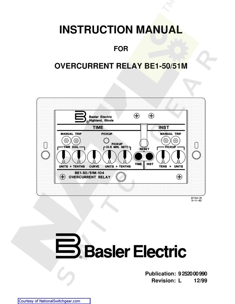
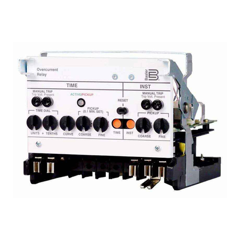
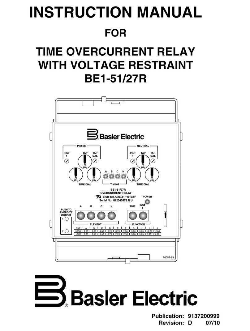
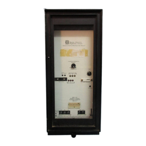
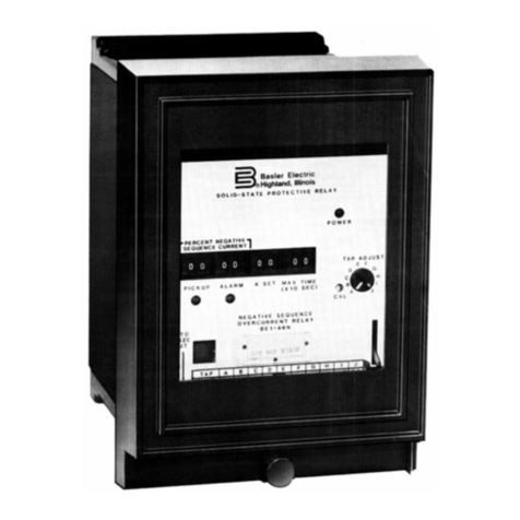
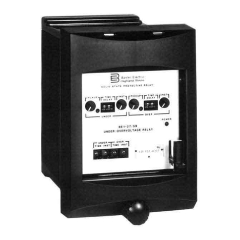
Basler BE1-50/51M-100 Series User manual

BE1-50/51M - Introduction i
W A R N I N G !
To avoid personal injury or equipment damage, only
qualified personnel should perform the procedures
presented in this manual.
INTRODUCTION
This manual provides information concerning the operation and installation of the BE1-50/51M
Overcurrent Relay. To accomplish this, the following is provided.
2
2
Specifications
2
2
Functional description
2
2
Mounting information
2
2
Setting procedure/example.
Courtesy of NationalSwitchgear.com

ii BE1-50/51M - Introduction
CONFIDENTIAL INFORMATION
OF BASLER ELECTRIC COMPANY, HIGHLAND, IL. IT IS LOANED FOR
CONFIDENTIAL USE, SUBJECT TO RETURN ON REQUEST, AND WITH THE
MUTUAL UNDERSTANDING THAT IT WILL NOT BE USED IN ANY MANNER
DETRIMENTAL TO THE INTEREST OF BASLER ELECTRIC COMPANY.
First Printing: April 1992
Printed in USA
© 1997, 1998, 1999, 2000 Basler Electric Co., Highland, IL 62249
November 2000
It is not the intention of this manual to cover all details and variations in equipment, nor does this
manual provide data for every possible contingency regarding installation or operation. The
availability and design of all features and options are subject to modification without notice. Should
further information be required, contact Basler Electric Company, Highland, Illinois.
BASLER ELECTRIC
ROUTE 143, BOX 269
HIGHLAND, IL 62249 USA
PHONE 618-654-2341 FAX 618-654-2351
Courtesy of NationalSwitchgear.com

BE1-50/51M - Introduction iii
CONTENTS
SECTION 1 GENERAL INFORMATION 1-1
Description ............................................. 1-1
Application .............................................. 1-1
Model Numbers .......................................... 1-4
Specifications ........................................... 1-5
Characteristic Curves ..................................... 1-13
SECTION 2 CONTROLS AND INDICATORS 2-1
SECTION 3 FUNCTIONAL DESCRIPTION 3-1
General ................................................. 3-1
Functional Description .................................... 3-1
Sensing Input ........................................ 3-1
Power Supply ........................................ 3-1
Instantaneous Signal .................................. 3-1
Time Signal .......................................... 3-1
Microprocessor ...................................... 3-1
Power-Off Sensing .................................... 3-2
Outputs ............................................. 3-2
SECTION 4 INSTALLATION 4-1
General ................................................. 4-1
Dielectric Test ........................................... 4-1
Mounting ............................................... 4-1
Outline Dimensions ................................... 4-2
Panel Drilling Diagram, C1 Case ........................ 4-3
Connections ............................................ 4-4
AC Input Connections ................................. 4-4
DC Control Connections ............................... 4-5
BE1-50/51M Overcurrent Relay, Rear View ................ 4-6
SECTION 5 TESTING 5-1
General ................................................. 5-1
Dielectric Test ........................................... 5-1
Operational Test Procedure ................................ 5-1
Test Equipment Required .............................. 5-1
Pickup and Timing Test Setup .......................... 5-2
Target Operational Test Setup .......................... 5-2
Test Procedure, Models BE1-50/51M-X04 and -X09 ......... 5-3
Test Procedure, Models BE1-50/51M-X00 and -X08 ......... 5-6
Setting the Relay ......................................... 5-8
Periodic Tests ........................................... 5-8
General ............................................. 5-8
Periodic Test ......................................... 5-8
Courtesy of NationalSwitchgear.com

iv BE1-50/51M - Introduction
CONTENTS- Continued
SECTION 6 MAINTENANCE 6-1
General .................................................6-1
In-House Repair ..........................................6-1
Storage .................................................6-1
Periodic Tests ...........................................6-1
General ..............................................6-1
Periodic Test .........................................6-2
SECTION 7 MANUAL CHANGE INFORMATION 7-1
SECTION 8 RELAY DIFFERENCES 8-1
Courtesy of NationalSwitchgear.com

BE1-50/51M General Information 1-1
SECTION 1 • GENERAL INFORMATION
DESCRIPTION
BE1-50/51M Overcurrent Relays are microprocessor based, non-directional phase or ground relays that
monitor the magnitude of a single phaseac current to provide accurate instantaneous and time overcurrent
protection for 50 hertz or 60 hertz power systems. Models are available with fifteen popular time
characteristics and a wide range of pickup settings.
APPLICATION
The wide range of pickup settings and front panel selectable time characteristics permit applications
involving coordination with fuses, reclosers, cold load pickup, motor starting, and fixed time requirements.
Integratingresetfunctionsare availabletosimulatethedisk resetofelectromechanicalrelays. BE1-50/51M
Overcurrent Relays have the following standard features.
&
Independent time and instantaneous elements.
&
A secure method to manually trip the breaker at the relay front panel.
&
Direct reading front panel controls.
&
Minimum pickup setting for safety during installation.
&
Time characteristics extend to a pickup multiple of 40.
&
Rugged draw-out construction with steel case.
&
Magnetic latching targets retain indication without power.
&
Built-in accuracy eliminates internal adjustments.
&
Minimum transient overreach.
&
Field selectable characteristic curve selection.
&
Field selectable instantaneous or integrating reset.
&
Field selectable 50 or 60 hertz operation.
&
Fieldselectablefixedinstantaneousdelay (0.0,0.1,0.2,or 0.3second on 100seriesrelays
and 0.0 or 0.1 second on 200 series relays.).
Individual models are available for 1 ampere and 5 amperes sensing input currents. BE1-50/51M
Overcurrent Relays (both horizontal and vertical mounts) must be removed from the case and installed on
a test bench for testing. Shorting contacts are provided for all current inputs when the relay chassis is
removed from the relay case. Figure 1-1 shows the front panel of the BE1-50/51M Overcurrent Relay, in
a C1, horizontal mount case. Figure 1-2 shows the front panel of the BE1-50/51M Overcurrent Relay, in a
C1, vertical mount case. Internally (circuit wise), all relay models are the same and use the same circuit
assemblies.
BE1-50/51M Overcurrent Relays have many advantages over other overcurrent relays. The five primary
advantages are:
&
Time characteristics are defined by equations and graphs.
&
Field selectable time characteristics.
&
Very low burden.
&
Self powered from the sensed current.
&
Continuous automatic calibration.
Courtesy of NationalSwitchgear.com
1-4 BE1-50/51M - General Information
MODEL NUMBERS
Model number variations in the BE1-50/51M Overcurrent Relays are specified by a three digit extension to
the model number. Tables 1-1 and 1-2 provide model number, case style, switch SW3-3 selections, and
sensing current input ranges. Internal switches provide for selecting system operating frequencies of 50 or
60 hertz, instantaneous element delays, curve sets, and instantaneous orintegrating reset characteristics.
The location and description of these switches is provided in Section 2. Integrating resetis available in 100
series relays (e.g. - BE1-50/51M-100) when there is adequate input currentto powerthe relay. Integrating
reset is available in 200 series relays (e.g. - BE1-50/51M-200) even when the input current falls to zero.
Two-hundred series relays also have additional characteristic curves available through curve set selection.
Table 1-1. BE1-50/51M Overcurrent Relays, One Ampere CT Secondary, 50/60 Hertz
Model Number Case Style SW3-3
Selects
Sensing Input Range (Amps)
TIME INST
BE1-50/51M-100* C1 (Horizontal Mount) 0.2 Second Delay 0.1 - 3.18 0.2 - 19.8
BE1-50/51M-200* C1 (Horizontal Mount) Curve Set 0.1 - 3.18 0.2 - 19.8
BE1-50/51M-108* C1 (Vertical Mount) 0.2 Second Delay 0.1 - 3.18 0.2 - 19.8
BE1-50/51M-208* C1 (Vertical Mount) Curve Set 0.1 - 3.18 0.2 - 19.8
Table 1-2. BE1-50/51M Overcurrent Relays, Five Ampere CT Secondary, 50/60 Hertz
Model Number Case Style SW3-3
Selects
Sensing Input Range (Amperes)
TIME INST
BE1-50/51M-104* C1 (Horizontal Mount) 0.2 Second Delay 0.5 - 15.9 1.0 - 99.0
BE1-50/51M-204* C1 (Horizontal Mount) Curve Set 0.5 - 15.9 1.0 - 99.0
BE1-50/51M-109* C1 (Vertical Mount) 0.2 Second Delay 0.5 - 15.9 1.0 - 99.0
BE1-50/51M-209* C1 (Vertical Mount) Curve Set 0.5 - 15.9 1.0 - 99.0
NOTE:
* 100 series relays (e.g. - BE1-50/51M-104) have the integrating reset
functionwhenthereisadequateinputcurrenttopower therelay. 200series
relays (e.g. - BE1-50/51M-204) have the integrating reset function even
when the input current falls to zero.
Courtesy of NationalSwitchgear.com
BE1-50/51M General Information 1-5
SPECIFICATIONS
BE1-50/51M Overcurrent Relays are available with the following features and capabilities.
Current Sensing Input
(1 Ampere Unit) Continuous current: 2.8 amperes. One second current: 80 amperes.
(5 Ampere Unit) Continuous current: 14 amperes. One second current: 400 amperes.
TIME PICKUP Range SettingtheTIMEPICKUPbelowtheminimumpickup(0.1on the 1 ampere
unit and 0.5 on the 5 ampere unit), places the relay in the most sensitive
state and may be used as a safety setting.
(1 Ampere Unit) 0.1 to 3.18 amperes in 0.02 ampere steps.
(5 Ampere Unit) 0.5 to 15.9 amperes in 0.1 ampere steps.
TIME Dropout Dropout occurs at 95% of pickup value.
TIME PICKUP
Accuracy The timing accuracy is the sum of +1 cycle +2%. This is over the range of
1.3 to 40 times tap. This accuracy is for a given measured multiple of tap.
The measurement of the multiple of taphas an accuracythat is the sum of
+2% +25 milliampere for 5 ampere units and +2% +5 milliamperes for 1
ampere units.
Example: (5 ampere unit)
PU Setting: 5 amperes
Current Applied: 6.5 amperes
+ Multiple Tolerance: 6.655 amperes
- Multiple Tolerance: 6.345 amperes
Time Curve: E
Time Dial: 5.0
Minimum Time Using 6.655 amperes: 46.5470 seconds
Maximum Time Using 6.345 amperes: 61.3968 seconds
Curve Time Using 6.5 amperes: 53.1800 seconds
Frequency Response A change of ±5 hertz from the nominal 50/60 hertz current causes less
than 0.5% change in the current required for pickup.
TIME DIAL Range
(1 Ampere Unit) 0.0 to 9.9, in 0.1 steps.
(5 Ampere Unit) 0.0 to 9.9, in 0.1 steps.
INST PICKUP Range Settingthe INSTPICKUP below theminimum pickup (0.2onthe 1 ampere
unit and 1.0 on the 5 ampere unit), places the relay in the most sensitive
state and may be used as a safety setting.
(1 Ampere Unit) 0.2 to 19.8 amperes in 0.2 ampere steps.
(5 Ampere Unit) 1 to 99 amperes in 1 ampere steps.
INST Dropout Dropout occurs at 95% of pickup value.
Courtesy of NationalSwitchgear.com
1-6 BE1-50/51M - General Information
INST PICKUP
Accuracy
(1 Ampere Unit) ±2% ±5 milliamperes at or above 0.2 ampere settings.
(5 Ampere Unit) ±2% ±25 milliamperes at or above 1.0 ampere settings.
Frequency Response A change of ±5 hertz from the nominal 50/60 hertz current causes less
than 0.5% change in the current required for pickup.
INSTTransientResponse Lessthan10%overreachwithsystemtimeconstantsupto 40 milliseconds
Burden Burden is non-linear. (Figure 1-3 illustrates the device burden.)
(1 Ampere Unit) At 0.1 amperes, Z = 120 ohms. At 1.0 ampere, Z = 5 ohms.
(5 Ampere Unit) At 0.5 amperes, Z = 4.8 ohms. At 5.0 amperes, Z = 0.2 ohms.
U.L. Recognition U.L. recognized per Standard 508, U.L. File Number E97033. Note:
Output contacts are not U.L. recognized for voltages greater than 250 V.
C.S.A. Certification C.S.A.certifiedperStandardCAN/CSA-C22.2Number14-M91,C.S.A.File
NumberLR23131-103s. Note: Outputcontactsare notC.S.A.certifiedfor
voltages greater than 250 V.
Courtesy of NationalSwitchgear.com
1-8 BE1-50/51M - General Information
Harmonic Response BE1-50/51M harmonic rejection is illustrated in Figure 1-4.
Figure 1-4 shows that a relay set for one ampere pickup would pickup at
0.96 ampere on a current containing 40% seventh harmonic. This
corresponds to a ten-to-one rejection ratio. Other conditions may be
evaluated in the same manner.
Figure 1-4. Harmonic Response
INST Characteristics BE1-50/51M instantaneous characteristic curves are similar to standard
electromechanical instantaneous units. However, the time to trip for
ground applications is slightly longer than that for phase applications to
allow time to power-up the relay. Longer trip time for ground applications
is beneficial because it helps to avoid nuisance trips.
For phase applications, the maximum time to trip is 3.5 cycles at a pickup
multiple of 1.0, and 1.5 cycles at a pickup multiple of 3.0. The
corresponding times for ground applications are 4.5 and 1.75 cycles.
Figure 1-5 shows the instantaneous characteristic curves for maximum
time to trip.
Courtesy of NationalSwitchgear.com
BE1-50/51M General Information 1-9
TAD
MC
BD K
TN
=-++
Figure 1-5. Instantaneous Characteristic Curves
INST Characteristics - Continued
On 100 series relays, additional delays of 0.1, 0.2, or 0.3seconds may be
added with internal switches SW3-2 and -3. These delays apply to both
phase and ground applications. Closing switch SW3-2 provides an
additional delay of 0.1 second. Closing switch SW3-3 provides an
additional delay of 0.2 second. Closing both switches SW3-2 and -3
provides an additional delay of 0.3 second. Section 2 illustrates the
location of SW3.
On200seriesrelays, an additionaldelay of0.1second may beaddedwith
internal switch SW3-2. This delay applies to both phase and ground
applications. Closing switch SW3-2 provides the additional delay of 0.1
second.
Time Characteristics Nine inverse time functions and one fixed time function can beselected by
afrontpanelswitch. Characteristiccurves forthe inverseanddefinite time
functions are defined by the following equation.
Where: D= TIME DIAL setting
M= Multiple of PICKUP
A, B, C, N, K = Constants for the particular curve
Courtesy of NationalSwitchgear.com
1-10 BE1-50/51M - General Information
Time Characteristics - Continued
Refer to Tables 1-3 or 1-4 for the time characteristic curve constants.
Constants have been selected to conform to the characteristics of
electromechanical relays over a range of pickup multiples from 1.3 to 40.
Values of the constants are available for use in computer relay setting
programs. Timing accuracy is the sum of ±1 cycle and ±2%.
The fixed time characteristic provides delays of 0.0 to 9.9 seconds
corresponding to the time dial setting. The time set is constant over a
rangeofpickup multiplesfrom1.0to40. Accuracyis ±2%±1cycle fortime
dial settings of 0.1 and greater.
Table 1-3. Time Characteristic Curve Constants
( Series 100 Relays or Series 200 Relays With SW3-3 Open (OFF) )
Curve Type Figure Constants
BE1 Similar To Number ABCNKR
S ABB CO-2 1-7 0.2663 0.03393 1.000 1.2969 0.028 0.500
L ABB CO-5 1-8 5.6143 2.18592 1.000 1.000 0.028 15.750
D ABB CO-6 1-9 0.4797 0.21359 1.000 1.5625 0.028 0.875
M ABB CO-7 1-10 0.3022 0.12840 1.000 0.5000 0.028 1.750
I ABB CO-8 1-11 8.9341 0.17966 1.000 2.0938 0.028 9.000
V ABB CO-9 1-12 5.4678 0.10814 1.000 2.0469 0.028 5.500
E ABB CO-11 1-13 7.7624 0.02758 1.000 2.0938 0.028 7.750
B BS142-B* 1-14 1.4636 0.00000 1.000 1.0469 0.028 3.250
C BS142-C* 1-15 8.2506 0.00000 1.000 2.0469 0.028 8.000
F None** None 0.0000 1.00000 0.000 0.0000 0.000 1.000
* Curves B and C are defined in British Standard BS142 and IEC 255-4 (International
Electrotechnical Commission)
** Fixed time from 0.1 to 9.9 seconds.
BE1 Curve Types:
S = Short Inverse V = Very Inverse
L = Long Inverse E = Extremely Inverse
D = Definite Time B = BS142 Very Inverse
M = Moderately Inverse C = BS142 Extremely Inverse
I = Inverse F = Fixed Time
Courtesy of NationalSwitchgear.com
BE1-50/51M General Information 1-11
()
T Time To Reset RD
M1
R2
=-
Table 1-4. Time Characteristic Curve Constants ( 200 Series Relays With SW3-3 Closed (ON)
Curve Type Figure Constants
BE1 Similar To Number A B C N K R
S GE IAC 55 1-16 0.0286 0.0208 1.000 0.9844 0.028 0.0940
L GE IAC 66 1-17 2.3955 0.00000 1.000 0.3125 0.028 7.8001
D ABB CO-6 1-9 0.4797 0.21359 1.000 1.5625 0.028 0.8750
M ABB CO-7 1-10 0.3022 0.12840 1.000 0.5000 0.028 1.7500
I GE IAC 51 1-18 0.2747 0.1042 1.000 0.4375 0.028 0.8868
V GE IAC 53 1-19 4.4309 0.0991 1.000 1.9531 0.028 5.8231
E GE IAC 77 1-20 4.9883 0.0129 1.000 2.0469 0.028 4.7742
B BS142-B* 1-14 1.4636 0.00000 1.000 1.0469 0.028 3.2500
C BS142-C* 1-15 8.2506 0.00000 1.000 2.0469 0.028 8.0000
F None** None 0.0000 1.00000 0.000 0.0000 0.000 1.0000
* Curves B and C are defined in British Standard BS142 and IEC 255-4 (International
Electrotechnical Commission)
** Fixed time from 0.1 to 9.9 seconds.
BE1 Curve Types:
S = Short Inverse V = Very Inverse
L = Long Inverse E = Extremely Inverse
D = Definite Time B = BS142 Very Inverse
M = Moderately Inverse C = BS142 Extremely Inverse
I = Inverse F = Fixed Time
Time Reset Reset occurs when the current drops below pickup and the relay has not
timed out. Switch SW3-4 provides selection of either an instantaneous or
integrating reset characteristic. Opening SW3-4 forces the instantaneous
reset timer to zero when timed dropout occurs. This fast reset
characteristic prevents the ratcheting effect that may occur with repeating
system faults. Closing SW3-4 selects the integrating reset characteristic.
The integrating reset characteristic simulates the disk reset of
electromechanical relays. When the integrating reset characteristic is
selectedon100seriesrelays,insurethatsufficientinputpowerisavailable
to power-up the relay. This is not required on Series 200 relays. Series
200 relays provide the integrating reset function even when input current
falls to zero.
Integrating reset characteristics are defined by the following equation and
shown in Figure 1-6. Equation constants are provided in Tables 1-3 and
1-4.
Where: R= Constant for the particular curve
D= TIME DIAL setting
M= Multiple of PICKUP
Courtesy of NationalSwitchgear.com
1-12 BE1-50/51M - General Information
1.0
10.0
100.0
0.0 0.2 0.4 0.6 0.8 1.0
Multiple of Pickup
xRD (Seconds)
This chart vertical axis xRD (Seconds) is applicable for all curves and is derived from
multiplying the constant Rfor the curve selected times D(the TIME DIAL setting).
Figure 1-6. Integrating Reset Characteristic Curve
Target Indicators Magnetically latched, manually reset targets indicate that current of 0.2
amperes or greater was present inthe trip circuit. Target coil resistance is
less than 0.1 ohms and operate time is less than one millisecond. See
50/51 Output specifications for maximum current rating.
50/51 Output Output contacts are surge protected and rated as follows:
Resistive:
120/240 Vac Make and carry 30 amperes for 0.2 seconds, carry 7 amperes for 2
minutes, 3 amperes continuously, and break 5 amperes.
125/250 Vdc Make and carry 30 amperes for 0.2 seconds, carry 7 amperes for 2
minutes, 3 amperes continuously, and break 0.3 ampere.
Inductive:
120/240 Vac, Make and carry 30 amperes for 0.2 seconds, carry 7 amperes for 2
125/250 Vdc minutes, 3 amperes continuously, and break 0.3 ampere. 0.3 amperes.
(L/R = 0.04).
AUX Output Output contacts can be configured in the field using jumpers to select
closing on either/or timed or instantaneous trip. Outputcontacts aresurge
protected and rated as follows:
Resistive:
120/240 Vac Make and carry 30 amperes for 0.2 seconds, carry 7 amperes
continuously, and break 5 amperes.
125/250 Vdc Make and carry 30 amperes for 0.2 seconds, carry 7 amperes
continuously, and break 0.3 ampere.
Inductive:
120/240 Vac, Make and carry 30 amperes for 0.2 seconds, carry 7 amperes
125/250 Vdc continuously, and break 0.3 ampere. (L/R = 0.04).
Courtesy of NationalSwitchgear.com

BE1-50/51M General Information 1-13
Isolation Meets IEC 255-5 and exceeds IEEE C37.90-1989, one-minute dielectric
(high potential) tests as follows:
All circuits to ground: 2828 Vdc
Input to Output Circuits: 2000 Vac or 2828 Vdc
Surge Withstand Capability
Oscillatory
Qualified to IEEE C37.90.1-1989
5VCPFCTF 5WTIG 9KVJUVCPF
%CRCDKNKV[ 59% 6GUVU HQT 2TQVGEVKXG 4GNC[U CPF 4GNC[ 5[UVGOU
Fast Transient
Qualified to IEEE C37.90.1-1989
Standard Surge Withstand
Capability (SWC) Tests for Protective Relays and Relay
Impulse Test Qualified to IEC 255-5.
Radio Frequency Field tested using a five watt, hand held transceiver operating at random
Interference (RFI) frequencies centered around 144 Mhz and 440 Mhz, with the antenna
located six inches from the relay in both horizontal and vertical planes.
Patent Patented in U.S., 1998, U.S. Patent No. 5751532.
UL Recognized/ UL Recognized per Standard 508, UL File No. E97033. CSA Certified per
CSA Certified Standard CAN/CSA-C22.2 No. 14-M91, CSA File No. LR 23131. Note:
Outputcontactsarenot ULRecognized/CSACertifiedfor voltagesgreater
than 250 volts.
Temperature Operating Range
-40
(
C (-40
(
F) to 70
(
C (158
(
F)
Recommended Storage Range
-50
(
C (-58
(
F) to 50
(
C (122
(
F). Parts are rated to 125
(
C (257
(
F),
however, the recommended storage range is as shown.
Shock 15 g in each of three mutually perpendicular planes.
Vibration 2 g in each of three mutually perpendicular planes swept over the range of
10 to 500 hertz for a total of six sweeps, 15 minutes each sweep.
Weight 5.2 pounds.
CHARACTERISTIC CURVES
Figures 1-7 through 1-15 illustrate the characteristic curves that are programmed into the nonvolatile
memory of series 100 relays. Figures 1-7 through 1-20 illustrate the characteristic curves that are
programmed into the nonvolatile memory of series 200 relays. To order full-size drawings of these
characteristic curves, contact Customer Service Department of the Power Systems Group, Basler Electric,
and request publication number 9 2520 00 999 (Figures 1-7 through 1-20). These publications contain full
size characteristic curves on transparent paper (vellum).
Courtesy of NationalSwitchgear.com
This manual suits for next models
7
Table of contents
Other Basler Relay manuals

Basler
Basler BE1-60 User manual

Basler
Basler BE1-79A User manual

Basler
Basler BE1-11g User manual

Basler
Basler BE1-25/79TR User manual

Basler
Basler BE1-32R User manual

Basler
Basler BE1-59NC User manual

Basler
Basler BE1-79 User manual

Basler
Basler BE1-50/51M-222 User manual

Basler
Basler BE1-79M User manual

Basler
Basler BE1-50M User manual

Basler
Basler BE1-50B-235 User manual

Basler
Basler BE1-51 User manual

Basler
Basler BE1-25 User manual

Basler
Basler BE1-700C User manual

Basler
Basler BE1-50/51B-232 User manual

Basler
Basler BE1-27 User manual

Basler
Basler BE1-59N User manual

Basler
Basler BE1-79A User manual

Basler
Basler BE1-50/51B-217 User manual

Basler
Basler BE1-50BF User manual