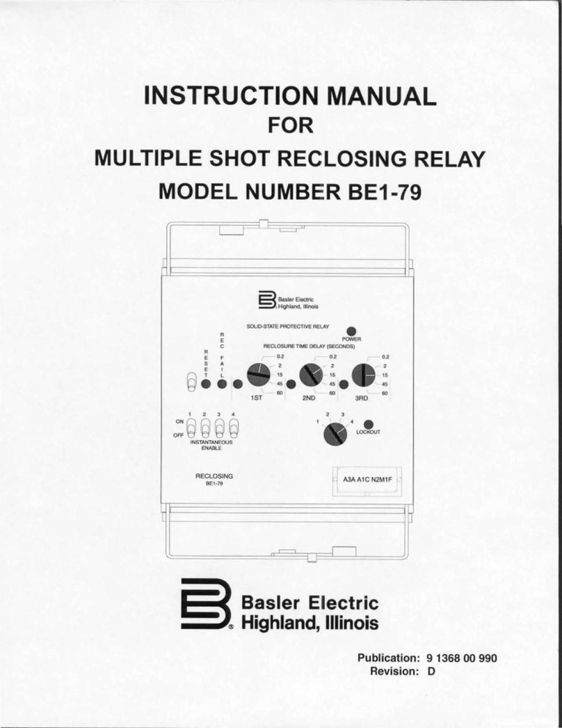
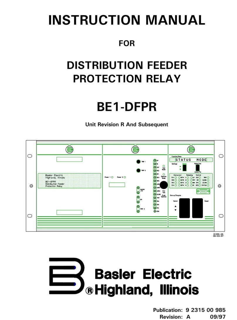
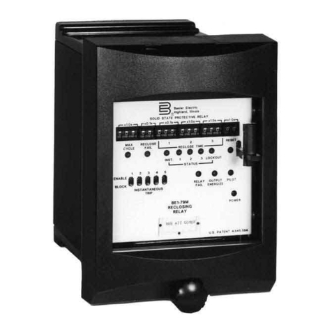
Basler BE1-79A User manual

INSTRUCTION MANUAL
for
BE1-79A
RECLOSING RELAY
Publication: 9 3102 00 990
Revision: D 08/2000

Introduction i
W A R N I N G !
TO AVOID PERSONAL INJURY OR EQUIPMENT
DAMAGE, ONLY QUALIFIED PERSONNEL SHOULD
PERFORM THE PROCEDURES PRESENTED IN THIS
MANUAL.
INTRODUCTION
ThismanualprovidesinformationconcerningtheoperationandinstallationoftheBE1-79AReclosingRelay.
To accomplish this, the following is provided.
Specifications
Functional Description
Installation Information
Testing Procedures

ii Introduction
CONFIDENTIAL INFORMATION
OF BASLER ELECTRIC COMPANY, HIGHLAND, IL. IT IS LOANED FOR
CONFIDENTIAL USE, SUBJECT TO RETURN ON REQUEST, AND WITH THE
MUTUAL UNDERSTANDING THAT IT WILL NOT BE USED IN ANY MANNER
DETRIMENTAL TO THE INTEREST OF BASLER ELECTRIC COMPANY.
First Printing: July 1997
Printed in USA
© 1997–2000 Basler Electric Co., Highland, IL 62249
August 2000
It is not the intention of this manual to cover all details and variations in equipment, nor does this manual
provide data for every possible contingency regarding installation or operation. The availability and design
ofall featuresand optionsare subjectto modification withoutnotice. Should further informationbe required,
contact Basler Electric Company.
BASLER ELECTRIC
ROUTE 143, BOX 269
HIGHLAND, IL 62249 USA
http://www.basler.com, [email protected]
PHONE 618-654-2341 FAX 618-654-2351

Introduction iii
PRODUCT REVISION HISTORY
The following information provides a historical summary of the changes made to the embedded software
(firmware)andhardwareofthisdevice.Thecorrespondingrevisionsmadetothisinstructionmanualarealso
summarized.Thisrevisionhistoryisseparatedintothreecategories:SoftwareChanges,HardwareChanges,
and Manual Revisions. All revisions are listed in chronological order.
Software Version Changes
1.01- 07/97
1.02 - 12/97 Initial release. (9 3102 00 100, 9 3102 00 101)
Initial release. (9 3102 00 200)
1.02 - 06/98 Communication was made consistent with other Basler products by
adding line feeds to ASCII data returned by the relay. Revision level
of 9 3102 00 100 was advanced to D. Revision level of 9 3102 00
101 was advanced to A.
1.05 - 08/00 This change is to the RS command. C(closed) and O(open) is
changed to E(energized) and D(de-energized). This is in conjunction
with the addition of the switch on the side that allows selection of NC
or NO operation of the RS contact.
Hardware Version Changes
07/97
12/97 Initial release. (9 3102 00 100, 9 3102 00 101)
Initial release. (9 3102 00 200)
10/98 Changed serialization to Hxxxxxxxx
01/00 Contact sensing jumpers added to the digital circuit board of relays
with part number 9 3102 00 101 gave inputs V1, V2, V3, and V4
three specific ranges of operating voltage.
08/00 Added a switch to allow for NO or NC operation of the RS contact.
Manual Revision Changes
A - 09/97 Information pertaining to the power supply holdup feature was
added.
B - 05/98 Patent information was added to Section 1. Various errors in
Sections 1, 3, and 6 were corrected.
C - 01/00 Information pertaining to the jumper-selectable contact sensing
voltage ranges was added. Drawings in Figure 5-1 were changed to
show the revised relay case cover. Various errors in Sections 1, 2, 3,
and 6 were corrected.
D - 08/00 Changed the manual to reflect modifications to the product. Closed
and open for the RS command is now energized and de-energized.
Added a switch to Figure 2-3 that allows the RS contact to be
selected to NC or NO.

iv Introduction
(This page is intentionally left blank.)

Introduction v
CONTENTS
SECTION 1 •GENERAL INFORMATION .............................................. 1-1
DESCRIPTION .................................................. 1-1
FEATURES ..................................................... 1-1
Controls And Indicators ......................................... 1-1
Communications .............................................. 1-1
Power HoldUp Circuit .......................................... 1-1
PRIMARY APPLICATION .......................................... 1-1
SPECIFICATIONS ................................................ 1-2
Reclose Timers ............................................... 1-2
Reset Timers ................................................. 1-2
Lockout Timer ................................................ 1-2
RS Timers ................................................... 1-2
Communication Port ........................................... 1-2
Power Supply ................................................ 1-2
Power Holdup Time ............................................ 1-2
Contact Sensing Inputs ......................................... 1-2
Output Contacts ............................................... 1-3
Environment ................................................. 1-3
Electrostatic Discharge (ESD) .................................... 1-3
Isolation ..................................................... 1-3
Surge Withstand Capability ...................................... 1-3
Radio Frequency Interference (RFI) ............................... 1-3
Shock ....................................................... 1-3
Vibration .................................................... 1-3
Weight ...................................................... 1-4
Patent ...................................................... 1-4
PART NUMBERS ................................................ 1-4
SECTION 2 •CONTROLS AND INDICATORS .......................................... 2-1
FRONT PANEL .................................................. 2-1
STYLE CONFIGURATION SWITCHES ................................ 2-2
INSTANTANEOUS RECLOSE JUMPER SWITCH ....................... 2-3
SECTION 3 •FUNCTIONAL DESCRIPTION ........................................... 3-1
GENERAL ...................................................... 3-1
HARDWARE .................................................... 3-1
S1 Description ................................................ 3-1
S2 Description ................................................ 3-1
CIRCUIT OPERATION ............................................ 3-1
Inputs ....................................................... 3-2
Microprocessor ............................................... 3-3
Outputs ..................................................... 3-3
INTERCONNECTIONS ............................................ 3-5
RECLOSER OPERATION .......................................... 3-8
Power-Up .................................................... 3-8
Reset ....................................................... 3-9
Lockout ..................................................... 3-9
Reclosing Sequences .......................................... 3-9

vi Introduction
CONTENTS(Continued)
SECTION 4 •COMMUNICATION .................................................... 4-1
GENERAL ....................................................... 4-1
ASCII COMMAND FORMAT ........................................ 4-1
Command Format:<CMD>[<;>CMD... ]<CR>[<LF>] .................. 4-1
Command Response Format : [<RESPONSE>][<ACK>] ............... 4-1
COMMAND DESCRIPTIONS ........................................ 4-2
Changing Settings Through The Serial Port .......................... 4-2
Access And Exit Commands ..................................... 4-2
Obtaining HELP Information Through The Serial Port .................. 4-3
Obtaining A Summary Of All Settings ............................... 4-3
Reclose And Reset Timer Setting Command ......................... 4-4
Lockout Timer Setting Command .................................. 4-4
RS Contact Setting Command .................................... 4-4
Alarm Output Command ......................................... 4-5
Relay Information Command ..................................... 4-5
SECTION 5 •INSTALLATION ....................................................... 5-1
GENERAL ....................................................... 5-1
MOUNTING ..................................................... 5-1
CONNECTIONS .................................................. 5-1
APPLICATION ................................................... 5-1
Style Configuration Switches ..................................... 5-1
Instantaneous Reclose Jumper Switch .............................. 5-1
Motor Input Voltage ............................................ 5-7
Contact Sensing Inputs ......................................... 5-7
Timing Cams ................................................. 5-8
Fault Clearing ................................................. 5-8
RS Contact ................................................... 5-8
Alarm Output ................................................. 5-8
Reset Switch ................................................. 5-8
COMMUNICATION CONNECTIONS AND SETTINGS .................... 5-9
Communication Connector ....................................... 5-9
Communication Settings ......................................... 5-9
RELAY INSTALLATION ........................................... 5-10
SECTION 6 •TESTING ............................................................ 6-1
INTRODUCTION ................................................. 6-1
INSTANTANEOUS RECLOSE TESTING ............................... 6-1
ACR11A Style Testing .......................................... 6-1
ACR11B Style Testing .......................................... 6-1
ACR11A and ACR11B Style Testing ............................... 6-1
DELAYED RECLOSE TESTING ..................................... 6-2
ACR11A Style Testing .......................................... 6-2
ACR11B Style Testing .......................................... 6-2
ACR11A and ACR11B Style Testing ............................... 6-2
POWER HOLDUP CIRCUIT TESTING ................................ 6-5
Part Number 9 3102 00 101 Relays ................................ 6-5
SECTION 7 MAINTENANCE .................................................. 7-1
BE1-79A General Information 1-1
SECTION 1 • GENERAL INFORMATION
DESCRIPTION
The BE1-79A Multiple Shot Reclosing Relay is an economical, microprocessor based relay that automatically
recloses circuit breakers which have been tripped by protective relays or other devices in power transmission
and distribution systems. The BE1-79A offers true “plug and play” convenience; itcan be installed in an existing
GEtypeS2casewithnowiringchangesrequired. GeneralElectrictypeACR11A,ACR11B,ACR11C,ACR11E,
and ACR11F reclosing relays can be directly replaced by the BE1-79A. The BE1-79A is also available in a
Basler S1 case for new installations.
FEATURES
BE1-79A Multiple Shot Reclosing Relays have the following standard features:
• Rugged construction in a draw-out steel case
• A maximum of four automatic reclosures
• A maximum of four automatic resets
• Lockout function
• Selectable instantaneous or delayed first reclosure
• Selectable internal or external instantaneous jumper
• Selectable normally closed or normally open RS output contact
• Selectable Relay Fail or Lockout
and
Relay Fail output contact
•Selectable contact sensing voltage range
Controls And Indicators
The front panel has indicators to verify relay power and recloser status. A Reset switch is provided to restore
the unit to the reset mode by clearing a reclosing sequence or a lockout condition. The left side of the relay
cradle has switches to configure the relay for either ACR11A or ACR11B operation. The right side of the cradle
has a switch(S4) to select either an internal or external jumper for an instantaneous first relcose. The left side
of the cradle has a switch(S5) to select either normally open or normally closed operation of the RS contact.
Communications
All relay settings are read or changed through the Serial Port located on the front panel. The BE1-79A uses
ASCII protocol.
Power HoldUp Circuit
The BE1-79A is available with an internal power holdup circuit. This circuitry enables the output contacts to be
maintained for a minimum of 40 cycles after nominal operating power is removed from relay terminals 5 and 6.
PRIMARY APPLICATION
The BE1-79A Multiple Shot Reclosing Relay automatically recloses circuit breakers which have been tripped
by protective relays or other devices in power transmission and distribution systems.
Over 90% of faults occurring on overhead lines may be cleared by momentarily de-energizing the line. Once
the circuit breaker has been opened to de-energize the line, the BE1-79A provides a reliable automatic
reclosure. The advantages are:
•Improved Service Continuity - returns the lineto service quickly, preserving line integrity and minimizing
outage effects on critical loads.
•System Stability - prevents disjointing of the system grid.
•Higher Line Availability - decreases likelihood of permanent loss of line
.

1-2 BE1-79A General Information
SPECIFICATIONS
BE1-79A relays have the following features and capabilities.
Reclose Timers
Reclose 1, Reclose 2, Reclose 3, and Reclose 4
Range: 0 to 300 seconds
Increments: 0.1 second
Accuracy: ±20 milliseconds ±1%, typical
±50 milliseconds ±1%, maximum
Reset Timers
Reset 1, Reset 2, Reset 3, Reset 4, and Final Reset
Range: 0 to 300 seconds
Increments: 0.1 seconds
Accuracy: ±20 milliseconds ±1%, typical
±50 milliseconds ±1%, maximum
Lockout Timer
Range: 0 to 300 seconds
Increments: 0.1 seconds
Accuracy: ±20 milliseconds ±1%, typical
±50 milliseconds ±1%, maximum
RS Timers
RS Set and RS Reset
Range: 0 to 300 seconds
Increments: 0.1 seconds
Accuracy: ±20 milliseconds ±1%, typical
±50 milliseconds ±1%, maximum
Communication Port
Parameters: 9600 baud, 8N1 half duplex
Protocol: ASCII
Power Supply
AC or DC operation: Range: 120 to 240 Vac
Range: 125 to 250 Vdc
Power Holdup Time
9 3102 00 101 Relays Only: 40 cycles (670 milliseconds) minimum, after loss of nominal
operating voltage
Contact Sensing Inputs
Operating Range
48 Vdc: 38.4 to 275 Vdc
125 Vdc/120 Vac: 100 to 275 Vdc or 96 to 264 Vac
250 Vdc/240 Vac: 200 to 275 Vdc or 192 to 264 Vac
Energizing Level: 80 percent of nominal
Current Draw: 1.5 milliamperes maximum per input
Recognition Time: 15 milliseconds for DC, AC(45-65 Hz), typical
25 milliseconds for DC, AC(45-65 Hz), maximum
Drop-Out Time: 15 milliseconds for DC, AC(45-65 Hz), typical
25 milliseconds for DC, AC(45-65 Hz), maximum

BE1-79A General Information 1-3
Output Contacts
Make and carry for tripping duty: 30 amperes for 0.2 seconds per IEEE C37.90;
7 amperes for 2 minutes
3 amperes continuous
Break Resistive or Inductive: 0.3 amperes at 125 or 250 Vdc (L/R=0.04 maximum)
Environment
Operating Temperature Range: -40C to 70C (-40F to 158F)
Storage Temperature Range: -40C to 85C (-40F to 185F)
Humidity: Qualified to IEC 68-2-38, 1st Edition 1974,
Basic
EnvironmentalTestProcedures,Part2:TestZ/AD:Composite
Temperature Humidity Cyclic Test
Electrostatic Discharge (ESD)
8 kV contact discharges and 15 kV air discharges applied in
accordance with IEC 801-2 ESD.
Isolation
1500 Vac at 50/60 Hz in accordance with IEEE C37.90
The RS-232 Serial Communication Port is intended only for
periodic use and is not subject to the requirements of IEEE
C37.90.
Surge Withstand Capability
Oscillatory: Qualified to IEEE C37.90.1-1989
Standard Surge Withstand
Capability (SWC) Tests for Protective Relays and Relay
Systems.
The RS-232 Serial Communication Port is intended
only for periodic use and is not subject to the requirements of
IEEE C37.90.1.
Fast Transient: Qualified to IEEE C37.90.1-1989
Standard Surge Withstand
Capability (SWC) Tests for Protective Relays and Relay
Systems.
The RS-232 Serial Communication Port is intended
only for periodic use and is not subject to the requirements of
IEEE C37.90.1.
Radio Frequency Interference (RFI)
Type tested using a five watt, hand-held transceiver in the
ranges of 144 and 440 megahertz with the antenna placed
within six inches of the relay.
Shock
In standard test, the relay has withstood 15 g in each of three
mutually perpendicular planes without structural damage or
degradation of performance.
Vibration
In standard tests, the relay has withstood 2 g in each of three
mutually perpendicular planes, swept over the range of 10 to
500 hertz for a total of six sweeps, 15 minutes each sweep,
without structural damage or degradation of performance.

1-4 BE1-79A General Information
Weight
S1: Maximum weight 13 pounds (including case)
S2: Maximum weight 5 pounds (excluding case)
Patent
Patent pending
PART NUMBERS
Table 1-1 lists the case style and special features of each version of the BE1-79A.
Table 1-1. BE1-79A Relay Model Numbers
Part Number Options Cradle
Style
9 3102 00 100 None S2
9 3102 00 101 Power Holdup Circuit S2
9 3102 00 200 Mounting Case Included S1

BE1-79A Controls And Indicators 2-1
Figure 2-1. BE1-79A Front Panel
SECTION 2 • CONTROLS AND INDICATORS
FRONT PANEL
Figure 2-1 shows the front panel controls and indicators for the BE1-79A Multiple Shot Reclosing Relay.
The following paragraphs describe each control and indicator and refer to the call-outs of Figure 2-1.
ARS-232 serial communications port. A computer terminal or PC running a terminal
emulation program such as Windows® Terminal can be connected to this port so that the
user may read or change the relay settings. Communication with the relay uses a simple
ASCII command language.
BPower LED. When this LED is ON, it indicates that operating power is applied to the relay.
CIdentification label shows the sensing input range, power supply type, serial number, and
part number.

2-2 BE1-79A Controls And Indicators
DLockout LED. When illuminated, this LED indicates that the relay is in LOCKOUT.
EIn Sequence LED. When this LED is ON, it indicates any one of the following:
Timing to reclose.
Timing to reset
Timing to lockout
Attempting to reclose
Attempting to reset
FReset LED. When illuminated, this LED indicates that the relay is in RESET.
GReset pushbutton switch. Pressing this momentary switch will clear the In Sequence or
Lockout LED and restore the relay to the Reset mode.
STYLE CONFIGURATION SWITCHES
The three switches on the left side of the relay cradle are used to configure the relay for either ACR11A or
ACR11B operation. For simplicity, recloser styles ACR11B, ACR11C, ACR11D, ACR11E, and ACR11F will be
referred to as ACR11B throughout this manual. Figure 2-2 illustrates the location of switches S1, S2, and S3.
Figure 2-2. Style Configuration Switches

BE1-79A Controls And Indicators 2-3
INSTANTANEOUS RECLOSE JUMPER SWITCH
The switches on the right side of the relay cradle are used to select either internal or external jumpering for an
instantaneous first reclosure and for selecting normally closed or normally open operation of the RS contact.
Figure 2-3 illustrates the location of switch S4, used to select internal or external jumpering, and S5, used to
select normally open or normally closed operation of the RS contact.
Figure 2-3. Instantaneous Reclose Jumper Switch
and RS contact selection switch

BE1-79A Functional Description 3-1
MICROPROCESSOR
C1
C2
C3
C4 C6 C8 C10
C5 C7 C9
ISO
ISO
ISO
ISO
ISO
EEPROM
Settin
g
s and Status
Memory
RAM
Operatin
g
Memory
ROM
Pro
g
ram
Memory
AC/DC
Power
Reset
Watch Do
g
Timer Circuit
Power Supply
RS-232
LED
Indicators
D2588-04
05/05/07
SECTION 3 • FUNCTIONAL DESCRIPTION
GENERAL
BE1-79A Multiple Shot Reclosing Relays are microprocessor based devices that provide automatic reclosing
of circuit breakers. This section describes the hardware, circuit operation, and software functional descriptions.
HARDWARE
The BE1-79A relay is available in an S1 cradle and case(200 series) or an S2 cradle without a case(100 series).
200 series Description
This BE1-79A consists of a fabricated steel and phenolic enclosure with a draw-out cradle assembly. The case
has the same overall dimensions as a Basler Electric or General Electric S1 case.
100 series Description
This BE1-79A consists of a draw-out cradle assembly which is intended for installation in an existing S2 case.
A case is not provided with the cradle assembly.
CIRCUIT OPERATION
Circuit operation is divided into
Inputs
,
Microprocessor
, and
Outputs
. Relay circuit functions are illustrated in
Figure 3-1 and described in the following paragraphs.
Figure 3-1. Functional Block Diagram

3-2 BE1-79A Functional Description
Inputs
There are four types of inputs to the BE1-79A relay. They are:
• Operating AC/DC Power
• Contact Sensing Inputs
• Reset Switch
• Serial Communication Port
Operating AC/DC Power.
Operating power for the internal circuitry is applied to the isolated internal switching
power supply. The power supply operates over a range of 120 to 240 Vac or 125 to 250 Vdc with no changes
in connections or jumpers required. The operating power input is not polarity sensitive and is not disrupted by
variations in the supply voltage or frequency over the power supply operating range. The power supply
generates 24 Vdc.
Part number 9 3102 00 101 relays are equipped with hold-up circuitry which maintains relay function for a
minimum of 40 cycles after nominal operating power is removed.
Contact Sensing Inputs.
The contact sensing inputs are designated V1, V2, V3, V4, and V5. Each input uses
an opto-isolator to provide isolation from external power sources. Each contact sensing input is rated for 48 Vdc
to 250 Vdc and 120 Vac to 240 Vac at 45 to 65 hertz.
Inputs V1 through V4 can operate at any one of three jumper-
selectable voltage ranges. Table 3-1 lists the nominal operating
voltage for each of the three jumper positions. Each input has a
dedicated jumper that is located on the digital circuit board.
JumperP3 controlsthe operatingvoltage forV1, P4controls V2,
P5 controls V3 and P6 controls V4. Instructions for placing each
jumper in the desired position are provided in Section 5,
Installation
. Input V5 is dedicated to monitoring the relay power
supply input and is not jumper selectable.
Note
In certain applications where 240 Vac control voltage is used, control circuit feedback
can occur through system inductive coupling. This feedback can result in erroneous
signals, causing relay operation. If there is a potential for control circuit feedback, the
jumper-selectable voltage range should be changed from the 48 Vdc factory default
setting to a higher position. Selections are provided in Table 3-1.
The function of each input depends on the operating configuration of the relay. Tables 3-2 and 3-3 describe the
function of each contact sensing input for each relay configuration. The G.E. nomenclature used for each input
is provided in parenthesis following each description.
Table 3-2. Contact Sensing Inputs Description For ACR11A Operation
Input Terminals Description
V1 3, 4 This input is typically connected to a 52A contact which results in voltage being
sensed when the breaker is closed. If V1 senses voltage within three seconds
after the Reset 1, 2, 3, or 4 timer expires, a reset will be initiated. If the relay is in
Lockout, a reset will be initiated anytime V1 senses voltage.
(E Reset)
Table 3-1. Contact Sensing Jumpers
Jumper Position Nominal Voltge
1 125 Vdc or 120
Vac
2 48 Vdc
3 250Vdc or 240Vac

BE1-79A Functional Description 3-3
V2 7, 8 This input is connected to a 52B contact which results in voltage being sensed
when the breaker is open. This input is typically used to provide an anti-pump
feature. If voltage is removed from V2 during a reclose attempt, the anti-pump
feature will prevent a further reclose attempt until the next reclose set time is
reached. This prevents multiple reclose attempts for a single reclose setting. (Z)
V3 11, 12 This input is used to monitor the 52B contact while the relay is in a reset condition.
When V3 senses voltage, the relay initiates a reclose sequence. (E Operate)
V4 --- This input is not used in this application.
V5 5, 6 This input is internally connected to the relay power supply terminal. A loss of
sensing voltage at this input will cause the relay to store all necessary data in
memory.
Table 3-3. Contact Sensing Inputs Description For ACR11B Operation
Input Terminals Description
V1 3, 4 This input is typically connected to a 52A contact which results in voltage being
sensed when the breaker is closed. If V1 senses voltage within three seconds
after the Reset 1, 2, 3, or 4 timer expires, a reset will be initiated. If the relay is in
Lockout, a reset will be initiated anytime V1 senses voltage.
(E Reset)
V2 6, 7 Voltage sensed at this input causes the relay to start a reclose sequence. (Motor)
V3 11, 12 This input is used to monitor the 52B contact while the relay is in a reset condition.
When V3 senses voltage, the relay initiates a reclose sequence.
(E Operate)
V4 11, 17 This input is connected to a 52B contact which results in voltage being sensed
when the breaker is open. This input is typically used to provide an anti-pump
feature. If voltage is removed from V4 during a reclose attempt, the anti-pump
feature will prevent a further reclose attempt until the next reclose set time is
reached. This prevents multiple reclose attempts for a single reclose setting. (Z)
V5 5, 6 This input is internally connected to the relay power supply terminal. A loss of
sensing voltage at this input will cause the relay to store all necessary data in
memory.
Reset Switch.
This momentary switch clears the In Sequence or Lockout LEDs located on the front panel and
restorestherelayto aresetcondition. Theresetswitchperforms thesamefunctionasthemanual clutchrelease
on the General Electric ACR11 relays. Operating power must be applied to terminals 5 and 6 for a reset to
occur.
Serial Communication Port.
The serial communication port is a standard RS-232 (DB-9) female connector
located on the front panel. This serial port provides the means to configure and read relay settings.
Microprocessor
All reclosing and communication functions are coordinated by the microprocessor. The BE1-79A uses an eight
bit microprocessor with integral ROM (read only memory) and RAM (random access memory). The
microprocessor is monitored by awatch-dog circuit which will reset the microprocessor if a problem is detected.
Outputs

3-4 BE1-79A Functional Description
The BE1-79A has ten outputs. The function of each output depends on the operating configuration of the relay.
Tables 3-3 and 3-4 provide a description of each output for each relay configuration.
Table 3-3. Outputs Description for ACR11A Operation
Output Terminals Description
C1 --- This output is not used in this application.
C2 13, 14 This output is closed during reset and open when voltage at input V3 is sensed.
During a reclose sequence, C2 will remain open until the relay returns to reset.
(E1)
C3 15, 16 This output functions as a programmable alarm contact . It can be set to function
as a Relay Fail output or a combination Relay Fail/Lockout output. A detailed
explanation is provided in the
Alarm Output Command
sub-section of Section 4,
Communication
. (JK)
C4 17, 18 This output is used in conjunction with the anti-pump function. C4 is closed
when voltage is sensed at input V2. (Z2)
C5 19, 20 This output is used in conjunction with the anti-pump function. C5 is closed
when voltage is sensed at input V2. (Z3)
C6 17, 20 This Reclose output closes for three seconds after a reclose timer expires. (AB)
C7 15, 20 This Anti-Pump output closes for the duration of a reclose timing except if output
C6 closes. If C6 closes, output C7 will close only if voltage is sensed at contact
sensin input V2. (BC+Z1)9KL
C8 9, 10 This RS output can be configured as a normally open or normally closed contact.
The output can be set to energize for an adjustable duration after the start of a
reclose cycle. The interval between the reclose sequence start and C8
energizing is also adjustable. A detailed explanation of programming the RS
output is provided in the
RS Contact Setting Command sub-section of
Section 4,
Communication
.
C9 --- This output is not used in this application.
C10 1, 2 This output is closed during a reset condition and open when a reclose timing
begins. (E4)
Table 3-4. Outputs Description for ACR11B Operation
Output Terminals Description
C1 12, 17 This output will close momentarily when voltage is sensed at input V4 and the
relay is in a reset condition. (Z29E6)
C2 13, 14 This output is closed during reset and open when voltage at input V3 is sensed.
During a reclose sequence, C2 will remain open until the relay returns to reset.
(E1)

Output Terminals Description
BE1-79A Functional Description 3-5
C3 15, 16 This output functions as an programmable alarm contact . It can be set to
function as a Relay Fail output or a combination Relay Fail/Lockout output. A
detailed explanation is provided in the
Alarm Output Command
sub-section of
Section 4,
Communication
. (JK)
C4 18, 19 This output is closed any time that the unit is not in reset. (E5)
C5 17, 19 This Reclose output closes for three seconds after a reclose timer expires. (AB)
C6 14, 17 This Anti-Pump output closes for the duration of a reclose timing except if output
C5 closes. If C5 closes, output C6 will close only if voltage is sensed at contact
sensing input V4. (BC9Z1)
C7 8, 20 This output is closed when the relay is in a lockout condition. (HI)
C8 9, 10 This RS output can be configured as a normally open or normally closed contact.
The output can be set to energize for an adjustable duration after the start of a
reclose cycle. The interval between the reclose sequence start and C8
energizing is also adjustable. A detailed explanation of programming the RS
output is provided in the
RS Contact Setting Command sub-section of
Section 4,
Communication
.
C9 5, 8 This output closes when the relay is in reset and voltage is sensed at input V3.
C9 will remain closed until the relay reaches either a lockout or reset condition.
(GH+E3)
C10 1, 2 This output is closed during a reset condition and open when a reclose timing
begins. (E4)
INTERCONNECTIONS
Figure 3-2 illustrates the interconnection of the contact sensing inputs, relay outputs, style configuration
switches,and instantaneous reclosejumper switchin theBE1-79A relay. Figure 3-2shows the relayconfigured
for an ACR11A application. Figure 3-3 shows the relay configured for an ACR11B application with an
instantaneous recloser jumper.

3-6 BE1-79A Functional Description
11 12 13 14 15 16 17 18 19 20
12345678910
C8
V1 V5 V2
V3 C3
C10
C2 C4 C5
C7
C9
S3
S1
S1
S2
S2
S4
INT EXT
AB
BA
C6
BA
A
B
BA
*
*
D2633-06
04-18-00
NC
NO
S5
Figure 3-2. Relay Interconnections
For ACR11A Applications
Other manuals for BE1-79A
1
Table of contents
Other Basler Relay manuals

Basler
Basler BE1-50 User manual

Basler
Basler BE1-67 User manual

Basler
Basler BE1-25 User manual

Basler
Basler Class 300 User manual

Basler
Basler BE1-87T User manual

Basler
Basler BE1-59N User manual

Basler
Basler BE1-51B User manual

Basler
Basler BE1-47N User manual

Basler
Basler BE1-50/51B-237 User manual

Basler
Basler BE1-51A User manual

Basler
Basler BE1-67N User manual

Basler
Basler BE1-50/51B-219 User manual

Basler
Basler BE1-51/27R User manual

Basler
Basler BE1-79 User manual

Basler
Basler BE1-49 User manual

Basler
Basler BE1-27 User manual

Basler
Basler BE1-47N User manual

Basler
Basler V3E Z1P B2C1F User manual

Basler
Basler H12345678 R U User manual

Basler
Basler BE1-27 User manual