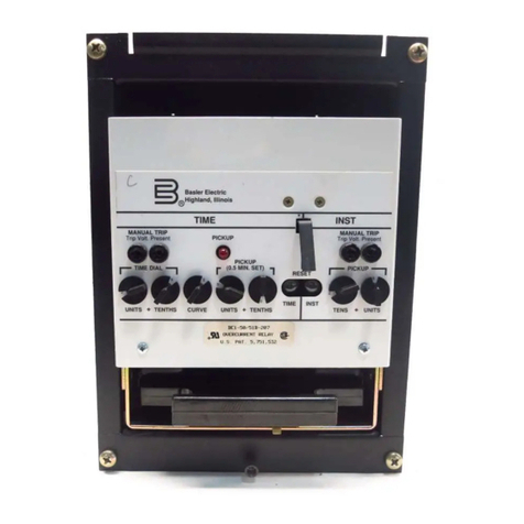
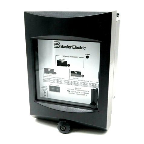
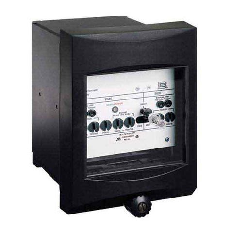
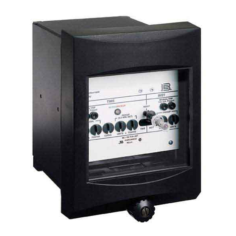
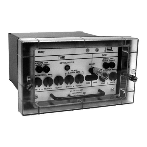
Basler BE1-51A User manual

INTRODUCTION
The
purpose
of
this
Instruction
Manual
is
to
furnish
information
concerning
the
operation
and
installation
of
this
device
.
To
accomplish
this
,
the
following
is
provided
.
Specifications
Functional
description
1
.
2
.
Operational
tests
3
.
Mounting
information
4
.
A
Service
Manual
,
publication
9
2011
00
620
is
available
as
an
aid
in
troubleshooting
and
repair
.
WARNING
TO
AVOID
PERSONAL
INJURY
OR
EQUIPMENT
DAMAGE
,
ONLY
QUALIFIED
PERSONNEL
SHOULD
PERFORM
THE
PROCEDURES
PRESENTED
IN
THIS
MANUAL
.
THIS
MANUAL
MAY
BE
USED
IN
PLACE
OF
EARLIER
EDITIONS
BEGINNING
WITH
REVISION
E
.
ING
PREVIOUS
EDITIONS
,
SEE
SECTION
6
.
FOR
INFORMATION
CONCERN
-
1
REV
A
B
C
D
E
F
ECA
9436
9621
9794
9913
10144
10757
Baaler
Electric
Highland
.
Winots
Courtesy of NationalSwitchgear.com

First
Printing
:
September
,
1987
Printed
in
USA
CONFIDENTIAL
INFORMATION
OF
BASLER
ELECTRIC
COMPANY
,
HIGHLAND
,
ILL
.
IT
IS
LOANED
FOR
CONFIDENTIAL
USE
,
SUBJECT
TO
RETURN
ON
REQUEST
,
AND
WITH
THE
MUTUAL
UNDERSTANDING
THAT
IT
WILL
NOT
BE
USED
IN
ANY
MANNER
DETRIMENTAL
TO
THE
INTEREST
OF
BASLER
ELECTRIC
COMPANY
.
It
is
not
the
intention
of
this
manual
to
cover
all
details
and
variations
in
equipment
,
nor
does
this
manual
provide
data
for
every
possible
contin
-
gency
regarding
installation
or
operation
.
The
availability
and
design
of
all
features
and
options
are
subject
to
modification
without
notice
.
Should
further
information
be
required
,
call
Basler
Electric
Company
,
Highland
,
Illinois
.
BOX
269
HIGHLAND
,
IL
62249
USA
PHONE
618
-
654
-
2341
FAX
618
-
654
-
2351
1
1
Courtesy of NationalSwitchgear.com

CONTENTS
SECTION
1
.
GENERAL
INFORMATION
1
-
1
1
-
1
Purpose
Time
Overcurrent
Monitoring
Instantaneous
Overcurrent
Monitoring
Model
and
Style
Number
Sample
Style
Number
Specifications
Characteristic
Curves
1
-
1
1
-
1
1
-
2
1
-
2
1
-
3
1
-
6
2
-
1
SECTION
2
.
CONTROLS
AND
INDICATORS
3
-
1
SECTION
3
.
FUNCTIONAL
DESCRIPTION
3
-
1
Current
Sensing
Tap
Block
Power
Supply
Enable
.
Pickup
,
Timing
,
Outputs
Targets
SECTION
4
.
TESTING
AND
INSTALLATION
3
-
2
3
-
2
3
-
2
3
-
2
3
-
2
3
-
3
3
-
3
4
-
1
4
-
1
General
Relay
Operating
Precautions
Dielectric
Test
Mounting
Connections
Operational
Test
Procedure
Instantaneous
Pickup
Time
Pickup
Accuracy
Timing
Instantaneous
Response
Time
Time
Current
Characteristics
....
Outline
Drawings
and
Drilling
Diagrams
SECTION
5
.
MAINTENANCE
4
-
1
4
-
1
4
-
2
4
-
2
4
-
2
4
-
2
4
-
2
4
-
3
4
-
3
4
-
4
4
-
5
5
-
1
General
.
. .
.
In
-
House
Repair
5
-
1
5
-
1
SECTION
6
.
MANUAL
CHANGE
INFORMATION
6
-
1
iii
Baaler
Electric
Highland
.
NUnots
Courtesy of NationalSwitchgear.com

SECTION
1
GENERAL
INFORMATION
PURPOSE
The
BE
1
-
51
A
is
a
single
-
phase
,
low
burden
,
time
overcurrent
relay
designed
to
provide
protection
for
generators
,
motors
,
transformers
,
and
lines
against
overload
and
fault
conditions
.
Standard
time
-
current
characteristics
and
a
wide
setting
range
provide
for
accurate
coordination
with
other
system
protective
functions
.
TIME
OVERCURRENT
MONITORING
Time
overcurrent
relays
are
used
to
provide
phase
and
ground
fault
protection
for
distribution
circuits
,
generators
,
transformers
,
and
other
major
components
of
the
power
system
.
The
relays
are
capable
of
a
wide
range
of
pickup
settings
and
characteristics
in
order
to
coordinate
properly
with
other
protective
devi
-
ces
in
the
power
system
.
The
BE
1
-
51
family
of
time
overcurrent
relays
provides
single
-
phase
current
sensing
.
These
relays
feature
a
pickup
setting
range
of
either
0.5
to
4.0
or
1.0
to
12.0
amperes
,
and
a
variety
of
timing
characteristics
for
proper
coor
-
dination
.
The
seven
standard
overcurrent
timing
functions
of
the
time
overcurrent
relay
provide
a
means
to
coordinate
with
other
protective
devices
,
and
to
discriminate
between
fault
currents
and
transitory
overloads
.
Table
1
-
1
illustrates
typical
applications
for
the
standard
time
overcurrent
characteristic
curves
.
INSTANTANEOUS
OVERCURRENT
MONITORING
One
instantaneous
output
,
independently
adjustable
for
current
level
,
may
be
specified
as
an
aid
in
coordinating
the
protection
scheme
.
TABLE
1
-
1
.
APPLICATIONS
SUMMARY
Typical
Protective
Application
Function
Special
Characteristics
Number
Name
Short
Inverse
Generators
,
busses
.
Relatively
short
time
,
desirable
where
preserving
system
stability
is
a
critical
factor
.
W
1
W
2
Long
Inverse
Motors
.
Provides
protection
for
starting
surges
and
overloads
of
short
duration
.
W
3
Definite
Time
General
use
.
Fixed
time
delay
according
to
dial
setting
.
Useful
in
sequential
tripping
schemes
.
Moderately
Inverse
Transmission
and
feeder
lines
,
Useful
in
both
phase
and
ground
fault
applications
.
Accommodates
moderate
load
changes
,
as
may
occur
on
parallel
lines
where
one
line
may
occasionally
have
to
carry
both
loads
.
W
4
W
5
Inverse
Very
Inverse
Extremely
Inverse
Feeder
lines
,
or
backup
protection
for
other
types
of
relays
.
Provides
additional
variations
of
the
inverse
characteristic
,
thereby
allowing
flexibility
in
meeting
load
variations
,
or
in
coordinating
with
other
relays
.
W
6
W
7
1
-
1
Basler
Electric
Highland
,
Illinois
Courtesy of NationalSwitchgear.com

BE
1
-
51
A
MODEL
AND
STYLE
NUMBER
The
electrical
characteristics
and
operational
features
included
in
a
specific
relay
are
defined
by
a
combination
of
letters
and
numbers
which
constitutes
the
device
'
s
style
number
.
The
model
number
,
BE
1
-
51
A
,
designates
the
relay
as
a
Basler
Electric
Class
100
Single
-
Phase
Time
Overcurrent
Relay
.
The
style
number
together
with
the
model
number
describe
the
features
and
options
in
a
particular
device
and
appear
on
the
front
panel
,
drawout
cradle
and
inside
the
case
assembly
.
STYLE
NUMBER
IDENTIFICATION
CHART
I
00
HDD
BE
1
-
51
A
MODEL
NO
.
OPTIOW
3
OPTION
1
POWER
SUPPLY
OUTPUT
SENSING
INPUT
TYPE
0
)
None
0
)
None
H
)
Current
Operated
E
)
Contacts
*
MO
K
)
Single
-
Phase
Current
1
)
Auxiliary
Contact
*
NO
1
)
Instantaneous
OverCurrent
Trip
Firetion
G
)
Contacts
•
NC
2
)
Auxiliary
Contact
•
NC
A
TARGET
OPTION
2
TIMING
SENSING
INPUT
RANGE
OPTION
4
N
)
None
U
1
)
Short
Inverse
A
)
Internally
Operated
A
)
Semi
-
Flush
Mounting
,
A
1
Size
Case
1
)
0.5
•
4.0
A
Pickup
Adjust
U
2
)
Long
Inverse
•
)
Currant
Operated
U
3
)
Definite
B
)
Projection
Mounting
,
A
1
Size
Case
2
)
1.0
-
12.0
A
Pickup
Adjust
NOTES
/
l
\
When
Target
is
MBM
,
Output
MUST
BE
MEM
•
W
4
)
Moderately
Inverse
F
)
Semi
-
Flush
Mounting
,
S
1
Size
Case
W
5
)
Inverse
U
6
)
Very
Inverse
P
)
Projection
Mounting
,
SI
Size
Case
W
7
)
Extremely
Inverse
SAMPLE
STYLE
NUMBER
The
style
number
identification
chart
above
illustrates
the
manner
in
which
a
relay
'
s
style
number
is
determined
.
For
example
,
if
the
style
number
were
K
1
E
-
W
5
M
-
B
1
N
2
A
the
device
would
have
the
following
features
:
K
-
Single
-
phase
current
sensing
.
1
-
Pickup
adjustment
range
of
0.5
A
to
4.0
A
for
Timed
Trip
.
E
-
Normally
open
main
output
contacts
.
W
5
-
Inverse
time
characteristics
.
M
-
Current
operated
power
supply
.
B
-
Current
operated
targets
.
1
-
Instantaneous
overcurrent
trip
function
included
.
N
-
None
2
-
Normally
closed
auxiliary
output
contacts
.
A
-
Semi
-
flush
mounting
,
A
1
size
case
.
1
-
2
Basler
Electric
Highland
,
Illinois
Courtesy of NationalSwitchgear.com

BE
1
-
51
A
SPECIFICATIONS
Current
sensing
input
is
nominally
rated
at
50
/
60
Hz
with
a
continuous
current
rating
of
5
times
the
TAP
setting
or
15
A
,
whichever
is
less
,
for
the
0.5
to
4.0
A
sensing
range
,
or
5
times
the
TAP
setting
or
20
A
,
whichever
is
less
,
for
the
1.0
to
12
.
OA
sensing
range
.
The
one
-
second
current
rating
is
50
times
the
TAP
setting
or
500
A
,
whichever
is
less
.
See
Table
1
-
2
for
typical
burden
data
.
The
power
supply
is
a
current
operated
supply
deriving
its
input
power
from
the
sensing
input
transformer
.
Two
current
sensing
ranges
are
available
and
defined
by
the
style
chart
:
0.5
A
to
4
.
OA
(
range
1
)
and
1.0
A
to
12
.
OA
(
range
2
)
.
Range
1
is
adjustable
in
discrete
settings
as
follows
:
0.5
,
0.6
,
0.7
,
0.8
,
1.0
,
1.2
,
1.5
,
2.0
,
2.5
,
3.0
,
3.75
,
and
4.0
.
Range
2
is
adjustable
in
discrete
settings
as
follows
:
1.0
,
1.2
,
1.5
,
2.0
,
2.5
,
3.0
,
4.0
,
5.0
,
6.0
,
7.5
,
10
,
and
12
.
Setting
selection
is
facilitated
by
a
TAP
block
and
screw
arrangement
.
At
25
°
C
,
within
+
2
%
of
the
selected
tap
setting
except
for
the
12
A
tap
,
which
is
within
+
5
%
.
Current
Sensing
Power
Supply
Pickup
Adjustment
Ranges
Pickup
Accuracy
Pickup
Accuracy
Over
the
Specified
Temperature
Range
Within
+
5
%
of
a
reference
measurement
taken
at
25
°
C
,
except
for
the
12
A
tap
,
which
is
within
+
8
%
.
Dropout
Within
10
%
of
pickup
value
.
Instantaneous
Pickup
Adjustment
(
Optional
)
Continuously
adjustable
from
1
to
40
times
the
selected
TAP
setting
of
the
time
overcurrent
function
.
Timing
Inverse
Time
Accuracy
There
are
seven
timing
characteristic
curves
available
(
W
1
through
W
7
)
.
The
timing
characteristic
of
a
specific
relay
is
defined
by
the
style
chart
.
Accuracy
is
within
+
7
%
or
+
30
milliseconds
of
the
indicated
time
for
any
combination
of
time
dial
and
pickup
settings
.
The
time
dial
is
adjustable
from
01
to
99
in
01
1
-
3
Basler
Electric
Highland
.
Illinois
Courtesy of NationalSwitchgear.com

BE
1
-
51
A
increments
.
A
setting
of
00
provides
an
instantaneous
response
to
an
overcurrent
condition
.
See
Time
Current
Characteristic
curves
,
Figures
1
-
2
through
1
-
8
.
Response
time
is
less
than
1.5
cycles
for
a
current
magnitude
of
two
times
selected
TAP
setting
(
for
any
TAP
setting
)
.
The
response
time
decreases
as
the
magnitude
of
the
input
signal
increases
.
(
Figure
1
-
1
.
)
Instantaneous
Response
Time
MULTIPLES
OF
TAP
Figure
1
-
1
.
Typical
Instantaneous
Response
Characteristics
Targets
Magnetically
latched
,
manually
reset
,
target
indicators
are
optionally
available
to
indicate
that
a
trip
output
contact
has
energized
.
Either
internally
operated
or
current
operated
targets
may
be
specified
.
Current
operated
targets
require
0.2
A
in
the
output
trip
circuit
to
actuate
,
and
trip
circuit
current
must
not
exceed
30
A
for
1
second
,
and
3
A
continuously
.
Current
operated
targets
may
be
selected
only
when
normally
open
(
NO
)
output
contacts
have
been
specified
.
1
-
4
Baaler
Electric
Highland
,
KUnois
Courtesy of NationalSwitchgear.com

BE
1
-
51
A
Output
contacts
are
rated
as
follows
.
Outputs
Resistive
120
/
240
Vac
-
make
,
break
,
and
carry
5
A
continuously
.
250
Vdc
-
make
and
carry
30
A
for
0.2
seconds
,
carry
5
A
con
-
tinuously
,
break
0.1
A
.
500
Vdc
-
make
and
carry
15
A
for
0.2
seconds
,
carry
5
A
con
-
tinuously
,
break
0.1
A
.
Inductive
120
/
240
Vac
,
125
Vdc
,
250
Vdc
-
break
0.1
A
(
L
/
R
=
0.04
)
.
15
g
in
each
of
three
mutually
perpen
-
dicular
axes
.
Shock
Vibration
2
g
in
each
of
three
mutually
perpen
-
dicular
axes
swept
over
the
range
of
10
to
500
Hz
for
a
total
of
six
sweeps
,
15
minutes
each
sweep
.
Because
of
the
use
of
surge
suppression
components
(
MOVs
)
at
all
of
the
input
and
output
terminals
,
a
HIP
0
T
test
cannot
be
performed
.
A
megger
test
(
500
Vdc
maximum
)
is
recommended
if
an
insulation
verification
is
required
.
The
following
are
acceptable
values
.
Dielectric
Test
All
terminals
to
terminal
7
:
Current
inputs
8
&
9
to
7
:
Outputs
2
,
3
,
4
,
5
,
4
6
to
7
:
From
2
,
3
,
4
,
5
,
6
to
8
&
9
:
100
MEG
min
;
1000
MEG
min
;
100
MEG
min
;
1000
MEG
min
.
Surge
Withstand
Capability
Qualified
to
ANSI
/
IEEE
C
37.90
-
1978
,
C
37.90
a
-
1974
,
and
IEC
255
.
Fast
Transient
Qualified
to
ANSI
/
IEEE
C
37.90
.
1
-
198
X
Impulse
Test
Qualified
to
IEC
255
-
5
Temperature
Operating
Storage
Weight
-
40
°
C
(
-
40
°
F
)
to
70
°
C
(
158
°
F
)
-
65
°
C
(
-
85
°
F
)
to
100
°
C
(
212
°
F
)
10.5
pounds
net
maximum
.
All
relays
may
be
supplied
in
either
an
A
1
or
SI
size
case
.
See
Section
4
for
dimension
and
drilling
diagrams
.
Case
Size
1
-
5
Batler
Electric
Highland
.
Illinois
Courtesy of NationalSwitchgear.com

BE
1
-
51
A
TABLE
1
-
2
.
BURDEN
DATA
R
+
jx
(
in
Ohms
)
at
Indicated
Applied
Current
Range
Selected
10
X
Tap
20
X
Tap
Tap
0.5
3
X
Tap
1
X
Tap
3.317
-
j
(
0.200
)
2.302
-
j
(
0.122
)
1.710
-
j
(
0.084
)
1.314
-
j
(
0.054
)
0.841
-
j
(
0.032
)
0.593
-
j
(
0.018
)
0.383
-
j
(
0.012
)
0.221
-
j
(
0.006
)
0.145
-
j
(
0.003
)
0.104
-
j
(
0.002
)
0.070
-
j
(
O
.
OOl
)
0.066
0.834
-
j
(
0.019
)
0.597
-
j
(
O
.
Oll
)
0.450
-
j
(
0.007
)
0.352
-
j
(
0.011
)
0.231
-
j
(
0.005
)
0.166
-
j
(
0.003
)
0.111
-
j
(
0.002
)
0.069
-
j
(
0.001
)
0.048
-
j
(
0.001
)
0.037
-
j
(
0.001
)
1.269
-
j
(
0.043
)
0.890
-
j
(
0.023
)
0.665
-
j
(
0.015
)
0.517
-
j
(
0.010
)
0.358
-
j
(
0.005
)
0.238
-
d
(
0.003
)
0.157
-
j
(
0.001
)
0.095
-
j
(
0.001
)
0.065
-
j
(
0.001
)
0.048
-
j
(
*
)
0.035
-
j
(
*
)
0.032
-
j
(
*
)
8.803
-
j
(
0.532
)
6.116
-
j
(
0.369
)
4.514
-
j
(
0.255
)
3.458
-
j
(
0.196
)
2.218
-
j
(
0.125
)
1.524
-
j
(
0.086
)
0.980
-
j
(
0.052
)
0.557
-
J
(
0.029
)
0.361
-
j
(
0.019
)
0.254
-
j
(
0.012
)
0.165
-
j
(
0.009
)
0.149
T
0.6
0.7
0.8
1.0
1.2
1.5
2.0
2.5
3.0
3.75
(
0.001
)
(
0.007
)
4.0
0.333
-
j
(
0.009
)
0.241
-
j
(
0.006
)
0.158
-
j
(
0.003
)
0.093
-
j
(
0.003
)
0.062
-
j
(
0.001
)
0.047
-
j
(
0.001
)
0.029
-
j
(
0.001
)
0.021
-
j
(
0.001
)
0.017
-
j
(
*
)
0.014
-
j
(
*
)
0.011
-
j
(
*
)
0.009
-
j
(
*
)
0.226
-
j
(
0.002
)
0.162
-
j
(
O
.
OOl
)
0.109
-
j
(
0.002
)
0.066
-
j
(
0.002
)
0.045
-
j
(
O
.
OOl
)
0.034
-
j
(
O
.
OOl
)
0.022
-
j
(
O
.
OOl
)
0.017
-
j
(
O
.
OOl
)
0.014
-
j
(
*
)
0.012
-
j
(
*
)
0.013
)
0.895
0.612
-
j
(
0.007
)
0.396
-
j
(
0.005
)
0.227
-
j
(
0.003
)
0.148
-
j
(
0.002
)
0.105
-
j
(
O
.
OOl
)
0.064
-
j
(
O
.
OOl
)
0.042
-
j
(
O
.
OOl
)
0.032
-
j
(
O
.
OOl
)
0.023
-
j
(
*
)
0.015
-
j
(
*
)
0.014
-
j
(
*
)
(
0.172
)
2
T
70
2.271
1.586
-
j
(
0.108
)
1.023
-
j
(
0.062
)
0.579
-
j
(
0.031
)
0.371
-
j
(
0.020
)
0.260
-
j
(
0.014
)
0.152
-
j
(
0.007
)
0.097
-
j
(
0.005
)
0.070
-
j
(
0.004
)
0.047
-
j
(
0.003
)
0.029
-
j
(
0.002
)
0.025
-
j
(
0.002
)
1.2
1.5
2.0
2.5
3.0
4.0
5.0
6.0
7.5
10.0
12.0
(
*
)
Less
than
0.0005
.
Burden
values
apply
to
50
Hz
and
60
Hz
units
.
Note
:
CHARACTERISTIC
CURVES
The
graphs
on
the
following
pages
illustrate
sample
curves
for
all
of
the
time
overcurrent
functions
available
as
options
.
NOTE
:
A
drawing
number
is
given
under
each
graph
.
Use
this
number
to
order
a
full
-
size
(
10
"
x
12
"
)
chart
from
Basler
Electric
Company
.
1
-
6
Basler
Electric
Highland
.
Mtnota
Courtesy of NationalSwitchgear.com

SECTION
2
CONTROLS
AND
INDICATORS
The
following
table
is
referenced
to
Figure
2
-
1
.
LOCATOR
CONTROL
OR
INDICATOR
FUNCTION
Magnetically
latching
,
manually
reset
target
indicators
trip
from
black
to
red
to
indicate
that
the
corresponding
output
relay
has
been
energized
.
Target
Indicators
A
PICKUP
Indicator
Red
LED
illuminates
to
indicate
that
the
pickup
setting
of
the
relay
has
been
ex
-
ceeded
.
B
Two
10
-
position
rotary
switches
used
to
select
a
particular
characteristic
curve
of
the
selected
set
of
inverse
curves
.
Adjustable
from
01
to
99
in
01
increments
.
A
setting
of
00
provides
an
instantaneous
response
to
the
overcurrent
condition
.
C
TIME
DIAL
INST
ADJUST
(
Optional
)
Multi
-
turn
potentiometer
used
to
establish
the
pickup
level
for
the
Instantaneous
overcurrent
function
of
the
relay
.
Con
-
tinuously
adjustable
from
1
to
40
times
the
selected
TAP
setting
of
the
overcur
-
rent
function
.
D
TAP
Block
E
Tap
block
and
screw
arrangement
is
used
to
establish
the
pickup
level
for
the
time
overcurrent
function
of
the
relay
.
See
Specifications
,
Section
1
,
for
definition
of
ranges
and
discrete
TAP
settings
.
F
Target
Reset
Lever
Mechanical
linkage
used
to
manually
reset
the
magnetically
latched
target
indicators
.
2
-
1
Basler
Electric
Highland
,
Illinois
Courtesy of NationalSwitchgear.com

BE
1
-
51
A
D
A
Basler
Electric
'
©
HighlamVnlinois
E
oo
0
0
INST
TIME
INST
PICKUP
TIME
DIAL
ADJUST
BE
1
-
51
A
SOLID
-
STATE
TIME
OVERCURRENT
RELAY
K
1
E
B
5
M
B
1
N
1
A
0.5
0.6
0.7
0.8
1.0
1.2
ooooo
©
oooooo
1.5
2.0
2.5
3.0
3.75
4.0
REMOVE
CONNECTING
PLUG
BEFORE
CHANGING
TAP
POSITION
CAUTION
:
Figure
2
-
1
.
Location
of
Controls
and
Indicators
2
-
2
Basler
Electric
Highland
,
Illinois
Courtesy of NationalSwitchgear.com

SECTION
3
FUNCTIONAL
DESCRIPTION
The
following
descriptions
are
referenced
to
the
Functional
Block
Diagram
,
Figure
3
-
1
below
.
POWER
SUPPLY
-
TO
INTERNAL
CIRCUITRY
JL
nr
INST
.
INSTANTANEOUS
PICKUP
ADJUST
INSTANTANEOUS
PICKUP
COMPARATOR
TRIP
o
T
A
TARCCT
P
INPUT
B
rs
piCKUPl
L
TIME
0
DIAL
C
JL
K
TIMED
TRIP
PICKUP
COMPARATOR
~
u
AUX
JL
~
U
TIMED
TIMING
060
-
003
TAAGEI
Figure
3
-
1
.
Functional
Block
Diagram
CURRENT
SENSING
The
BE
1
-
51
A
Time
Overcurrent
Relay
'
s
input
transformer
senses
a
single
phase
of
system
current
,
receiving
its
input
,
in
turn
,
from
the
(
5
A
nominal
)
secondary
of
a
system
transformer
.
The
sensing
input
transformer
is
nominally
rated
at
50
/
60
Hz
,
with
a
maximum
burden
of
10
VA
at
TAP
value
current
.
The
continuous
current
rating
is
dependent
upon
the
input
range
selected
.
For
range
1
(
0.5
to
4.0
A
)
the
maximum
continuous
rating
is
5
times
TAP
or
15
A
,
whichever
is
less
.
For
range
2
(
1.0
to
12
.
OA
)
the
maximum
continuous
rating
is
5
times
TAP
or
20
A
,
whichever
is
less
.
One
-
second
current
rating
is
defined
as
50
times
TAP
or
500
A
,
whichever
is
less
.
For
current
ratings
below
one
second
,
the
rating
may
be
calculated
using
the
formula
I
2
=
K
/
T
where
T
is
the
time
in
seconds
that
the
current
flows
,
and
K
=
(
50
X
tap
)
2
.
When
the
connecting
plug
(
"
paddle
"
)
is
removed
,
the
CT
inputs
are
shorted
.
3
-
1
Basler
Electric
Highland
.
Illinois
Courtesy of NationalSwitchgear.com
Table of contents
Other Basler Relay manuals

Basler
Basler BE1-51/27R User manual

Basler
Basler BE1-79A User manual

Basler
Basler BE1-50/51B-218 User manual

Basler
Basler H12345678 R U User manual

Basler
Basler BE1-50B-235 User manual

Basler
Basler BE1-60 User manual

Basler
Basler BE1-50/51B-219 User manual

Basler
Basler BE1-50/51B-229 User manual

Basler
Basler BE1-50BF User manual

Basler
Basler BE1-59N User manual

Basler
Basler BE1-51/27R User manual

Basler
Basler BE1-50 User manual

Basler
Basler BE1-47N User manual
Basler
Basler BE1-59N User manual

Basler
Basler BE1-50/51M-100 Series User manual

Basler
Basler BE1-51C User manual

Basler
Basler BE1-50B User manual
Basler
Basler BE1-51 User manual

Basler
Basler BE1-79A User manual

Basler
Basler BE1-700C User manual