Batco 2500 Series User manual

Part Number: P1511025 R0
Revised: Jun/11
Read this manual before using product. Failure
to follow instructions and safety precautions can
result in serious injury, death, or property
damage. Keep manual for future reference.
PITSTOP
2500 SERIES
OPERATION MANUAL

This product has been designed and constructed according to general engineering
standardsa. Other local regulations may apply and must be followed by the operator.
We strongly recommend that all personnel associated with this equipment be trained
in the correct operational and safety procedures required for this product. Periodic
reviews of this manual with all employees should be standard practice. For your
convenience, we include this sign-off sheet so you can record your periodic reviews.
a. Standards include organizations such as the American Society of Agricultural and Biological Engineers,
American National Standards Institute, Canadian Standards Association, International Organization for
Standardization, and/or others.
Date Employee Signature Employer Signature

TABLE OF CONTENTS
BATCO - PITSTOP
2500 SERIES
P1511025 R0 3
1. Introduction .......................................................................................................................... 5
2. Safety First............................................................................................................................ 7
2.1. General Safety ......................................................................................................... 8
2.2. Assembly Safety....................................................................................................... 9
2.3. Operational Safety.................................................................................................... 9
2.4. Transport Safety....................................................................................................... 9
2.5. Storage Safety........................................................................................................ 10
2.6. Maintenance Safety............................................................................................... 10
2.7. Hydraulic Safety..................................................................................................... 10
2.8. Electric Motor Safety.............................................................................................. 10
2.9. Tire Safety.............................................................................................................. 11
2.10. Safety Decal Locations......................................................................................... 11
2.10.1. Decal Installation.................................................................................... 11
2.10.2. Decal Locations...................................................................................... 11
3. Machine Components........................................................................................................ 15
3.1. Controls.................................................................................................................. 16
3.2. Matching Equipment............................................................................................... 17
4. Assembly ............................................................................................................................ 19
4.1. Electric Top Drive Assembly ................................................................................. 19
4.2. Hydraulic Drive Kit.................................................................................................. 21
4.3. Electric Wet Kit....................................................................................................... 22
5. Transport............................................................................................................................. 25
5.1. Pre-Transport Checklist.......................................................................................... 25
5.2. Transport Procedure .............................................................................................. 25
6. Placement ........................................................................................................................... 29
6.1. Set-Up Conversions............................................................................................... 29
7. Operation ............................................................................................................................ 31
7.1. Pre-Operation Checklist......................................................................................... 31
7.2. Machine Break-In And Operation.......................................................................... 31
7.2.1. Starting Conveyor:.................................................................................... 32
7.2.2. Conveyor Shutdown:................................................................................ 33
7.2.3. Truck Positioning:..................................................................................... 33
7.2.4. Emergency Shutdown: ............................................................................. 34
7.2.5. Re-Starting (Full Tube):........................................................................... 34
7.2.6. Grain Removal.......................................................................................... 34
7.2.7. Optional Self-Contained Hydraulics:......................................................... 34
7.2.8. Operating Tips:......................................................................................... 34
8. Storage................................................................................................................................ 35

TABLE OF CONTENTS
BATCO - PITSTOP
2500 SERIES
4P1511025 R0
9. Maintenance........................................................................................................................ 37
9.1. Maintenance Schedule........................................................................................... 37
9.1.1. Initial start-up servicing............................................................................. 37
9.1.2. 40 Hours or Weekly:................................................................................. 37
9.1.3. Every 100 Hours or Annually:................................................................... 37
9.2. Maintenance Checklist ........................................................................................... 38
9.3. Service & Maintenance Procedures....................................................................... 38
9.3.1. Fluids and Lubricants................................................................................ 38
9.3.2. Greasing................................................................................................... 39
9.3.3. Conveyor Belt Tension ............................................................................. 39
9.3.4. Conveyor Belt Alignment.......................................................................... 40
9.3.5. Belt Relacing............................................................................................. 42
9.3.6. Electric Drive Belt Tension & Alignment................................................... 43
9.3.7. Hydraulic Oil Level.................................................................................... 44
10. Troubleshooting ............................................................................................................... 47
11. Appendix .......................................................................................................................... 49
11.1. Mechanical Specs ................................................................................................ 49
New Equipment Warranty ....................................................................................................... 51

BATCO - PITSTOP 1. INTRODUCTION
2500 SERIES
P1511025 R0 5
1.Introduction
Congratulations on your choice of a Batco PitStop to complement your agricul-
tural operation. This equipment has been designed and manufactured to meet
the needs of the discriminating buyer for the efficient movement of grain, pulse
crops, fertilizer, and other granular materials.
Safe, efficient, and trouble-free operation of your PitStop requires that you, and
anyone else who will be operating or maintaining the conveyor, read and under-
stand the safety, operation, maintenance, and troubleshooting information
contained within this manual.
Equipment is available in various combinations. In most cases, the following
instructions will apply to all machines. Where the assembly information varies,
additional instructions will be included and will be indicated with an arrow.
Keep this manual handy for frequent reference and to pass on to new operators
or owners. Call your Batco distributor or dealer if you need assistance, infor-
mation, or additional copies of the manual.
Always give your dealer the serial number of your Batco PitStop Conveyor when
ordering parts or requesting service or other information.
The serial number plate is located where indicated. Please mark the number in
the space provided for easy reference.
Model #
Serial #
Production Year

1. INTRODUCTION BATCO - PITSTOP
2500 SERIES
6P1511025 R0

BATCO - PITSTOP 2. SAFETY FIRST
2500 SERIES
P1511025 R0 7
2.Safety First
The Safety Alert symbol to the left identifies important safety messages on the
product and in the manual. When you see this symbol, be alert to the possibil-
ity of personal injury or death. Follow the instructions in the safety messages.
Why is SAFETY important to you?
Three big reasons:
• Accidents disable and kill.
• Accidents cost.
• Accidents can be avoided.
SIGNAL WORDS
Note the use of the signal words DANGER, WARNING, CAUTION, and NOTICE
with the safety messages. The appropriate signal word for each message has
been selected using the definitions below as a guideline.
The Safety Alert symbol means: “ATTENTION, BE ALERT! YOUR SAFETY IS
INVOLVED”.
DANGER
Indicates an imminently hazardous situation
that, if not avoided, will result in serious injury
or death.
WARNING
Indicates a hazardous situation that, if not
avoided, could result in serious injury or
death.
CAUTION
Indicates a hazardous situation that, if not
avoided, may result in minor or moderate
injury.
NOTICE
Indicates a potentially hazardous situation that, if not
avoided, may result in property damage.

2. SAFETY FIRST BATCO - PITSTOP
2.1. GENERAL SAFETY 2500 SERIES
8P1511025 R0
2.1. GENERAL SAFETY
Important: The general safety section includes instructions that apply to all safety practices.
Any instructions specific to a certain safety practice (e.g., assembly safety), can
be found in the appropriate section. Always read the complete instructional
sections and not just these safety summaries before doing anything with the
equipment.
YOU are responsible for the SAFE use and maintenance of your equipment.
YOU must ensure that you and anyone else who is going to work around the
equipment understands all procedures and related SAFETY information
contained in this manual.
Remember, YOU are the key to safety. Good safety practices not only protect
you, but also the people around you. Make these practices a working part of your
safety program.
• It is the equipment owner and the operator's responsibility to read and under-
stand ALL safety instructions, safety decals, and manuals and follow them
before assembling, operating, or maintaining the equipment. All accidents
can be avoided.
•Equipment owners must give instructions and review the information initially
and anually with all personnel before allowing them to operate this product.
Untrained users/operators expose themselves and bystanders to possible
serious injury or death.
• Use this equipment for its intended purposes only.
• Do not modify the equipment in any way. Unauthorized modification may
impair the function and/or safety, and could affect the life of the equipment.
Any modification to the equipment voids the warranty.
• Do not allow children, spectators, or bystanders within the work area.
•Have a first-aid kit available for use should the need arise, and know how to
use it.
•Provide a fire extinguisher for use in case of an accident. Store in a highly vis-
ible place.
•Wear appropriate protective gear. This list includes, but
is not limited to:
• a hard hat
•gloves
• protective shoes with slip-resistant soles
• protective goggles
• hearing protection
• dust mask or respirator
• For Powered Equipment: before servicing, adjusting, or repairing powered
equipment, unplug, place all controls in neutral or off position, stop the engine
or motor, remove ignition key or lock out power source, and wait for all mov-
ing parts to stop.

BATCO - PITSTOP 2. SAFETY FIRST
2500 SERIES 2.2. ASSEMBLY SAFETY
P1511025 R0 9
•Follow good shop practices:
• keep service area clean and dry
• be sure electrical outlets and tools are properly
grounded
• use adequate light for the job at hand
• Think SAFETY! Work SAFELY!
2.2. ASSEMBLY SAFETY
• Read through the instructions to get to know the sub-assemblies and hard-
ware that make up the equipment.
• Do not take chances with safety. The components are large, heavy, and can
be hard to handle. Always use the proper tools, stands, jacks, and hoists for
the job.
• Always have 2 or more people assembling the equipment. Because of the
weight, do not attempt assembly alone.
2.3. OPERATIONAL SAFETY
• Before servicing, adjusting, repairing, or unplugging powered products
(including hydraulic and electric motor drives).
• Do not allow riders when transporting.
• Do not operate machine with any guards removed.
2.4. TRANSPORT SAFETY
• Check with local authorities regarding transport on public roads. Obey all
applicable laws and regulations.
• Always travel at a safe speed, never exceeding 20 mph (32 km/h). Reduce
speed on rough surfaces. Use caution when turning corners or meeting traf-
fic.
• Make sure the SMV (slow moving vehicle) emblem and all the lights and
reflectors that are required by local authorities are in place, are clean, and
can be seen by all over-taking and oncoming traffic. Always use hazard-warn-
ing flashers on tractor/towing vehicle when transporting unless prohibited by
law.
• Use the optional light package and highway tires when transporting with a
truck on the highway.
• Be sure that the unit is hitched securely to the towing vehicle. Always use a
retainer through the hitch, and a safety chain between the machine and the
towing unit.
• Keep to the right and yield the right of way to allow faster traffic to pass. Drive
on the road shoulder if permitted by law.

2. SAFETY FIRST BATCO - PITSTOP
2.5. STORAGE SAFETY 2500 SERIES
10 P1511025 R0
2.5. STORAGE SAFETY
• Store the unit in an area away from human activity.
• Do not permit children to play on or around the stored equipment.
2.6. MAINTENANCE SAFETY
• Before applying pressure to a hydraulic system, ensure all components are
tight and that hoses and couplings are in good condition.
• Relieve pressure from hydraulic circuit system before servicing or disconnect-
ing from tractor.
• Before resuming work, install and secure all guards when maintenance work
is complete.
2.7. HYDRAULIC SAFETY
• Always place all tractor hydraulic controls in neutral before disconnecting
from tractor or working on hydraulic system.
• Make sure that all components in the hydraulic system are kept in good con-
dition and are clean.
• Replace any worn, cut, abraded, flattened, or crimped hoses.
• Do not attempt any makeshift repairs to the hydraulic fittings or hoses by
using tape, clamps, or cements. The hydraulic system operates under
extremely high-pressure. Such repairs create a hazardous and unsafe condi-
tion because they will fail suddenly.
• Wear proper hand and eye protection when searching for a high-pressure
hydraulic leak. Do not use hands. Use a piece of wood or cardboard as a
backstop to isolate and identify a leak.
•If injured by a concentrated
high-pressure stream of
hydraulic fluid, seek medical
attention immediately. Seri-
ous infection or toxic reaction
can develop from hydraulic
fluid piercing the skin surface.
• Relieve pressure from hydrau-
lic circuit before servicing or disconnecting from tractor.
2.8. ELECTRIC MOTOR SAFETY
For units with electric motors.
• To prevent serious injury or death, only qualified personnel should service
electrical components.
• Keep electrical components in good repair.
• Ground electric motor before using.

BATCO - PITSTOP 2. SAFETY FIRST
2500 SERIES 2.9. TIRE SAFETY
P1511025 R0 11
• Inspect drive belts before using. Replace if frayed or damaged.
2.9. TIRE SAFETY
• Failure to follow proper procedures when mounting a tire on a wheel or rim
can produce an explosion that may result in serious injury or death.
• Do not attempt to mount a tire unless you have the proper equipment and
experience to do the job.
• Have a qualified tire dealer or repair service perform required tire mainte-
nance.
2.10. SAFETY DECAL LOCATIONS
• Keep safety decals clean and legible at all times.
• Replace safety decals that are missing or have become illegible. See decal
location figures that follow.
• Replaced parts must display the same decal(s) as the original part.
• Safety decals are available from your distributor, dealer, or factory.
2.10.1. DECAL INSTALLATION
1. Decal area must be clean and dry, with a temperature above 50°F (10°C).
2. Decide on the exact position before you remove the backing paper.
3. Align the decal over the specified area and carefully press the small portion
with the exposed sticky backing in place.
4. Slowly peel back the remaining paper and carefully smooth the remaining
portion of the decal in place.
5. Small air pockets can be pierced with a pin and smoothed out using the sign
backing paper.
2.10.2. DECAL LOCATIONS
Replicas of the safety decals that are attached to the equipment are shown in the
figure(s) that follow. Proper safety procedures require that you familiarize
yourself with the various safety decals and the areas or particular functions that
the decals apply to as well as the safety precautions that must be taken to avoid
serious, injury, death, or damage.
Think SAFETY! Work SAFELY!

2. SAFETY FIRST BATCO - PITSTOP
2.10. SAFETY DECAL LOCATIONS 2500 SERIES
12 P1511025 R0
Figure 2.1 Safety Decals

BATCO - PITSTOP 2. SAFETY FIRST
2500 SERIES 2.10. SAFETY DECAL LOCATIONS
P1511025 R0 13
Figure 2.2 Safety Decal Locations

2. SAFETY FIRST BATCO - PITSTOP
2.10. SAFETY DECAL LOCATIONS 2500 SERIES
14 P1511025 R0

BATCO - PITSTOP 3. MACHINE COMPONENTS
2500 SERIES
P1511025 R0 15
3.Machine Components
The Batco PitStop Conveyor is designed to allow trucks to drive-over the
machine, and dump into the hopper and conveyor belt from on top.
The hopper or intake frame is ramped to allow the truck to drive over the intake
when positioning. The collapsible hopper sides drop for truck positioning and
raise for unloading.
A flat conveyor belt moves material from the hopper and out the discharge.
Normally, the discharge is directed into another conveying system. Electric or
hydraulic power options are available to drive the belt. The wheel assembly is
positioned with hydraulic cylinders, and is moved down for transport and up for
operation. A self-contained hydraulic package option is available if hydraulic
power is not available to raise and lower the wheel assembly.
See Figure 3.1 for a list of components.
Figure 3.1
3. MACHINE COMPONENTS BATCO - PITSTOP
3.1. CONTROLS 2500 SERIES
16 P1511025 R0
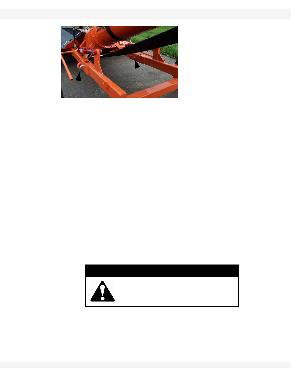
Figure 3.2 Wheel Assembly Lock Pin (in Transport Configuration)
3.1. CONTROLS
Before starting, all operators should familiarize themselves with the location and
function of the controls.
1. Electric Drive
• Move the switch up for ON and down for OFF.
2. Hydraulic Drive
• Refer to tractor operation manual.
3. Winch
• A winch is located on the top of the discharge tube and is used to raise
and lower the sides of the intake hopper. Turn the handle counterclock-
wise to lower, and clockwise to raise the sides.
4. Lift Valve
• This valve allows oil to flow into or out of the hydraulic cylinder that raises
or lowers the wheel assembly. Lift the handle to lower the wheels and
raise the frame. Move the handle down to lower the frame and raise the
wheel. Release the handle and it will return to its centered, neutral posi-
tion. The wheel assembly lock pins must be removed to raise and lower
the machine and secured in place with a hairpin washer transporting as
shown in Figure 3.2.
WARNING
Ensure that the operator is safely positioned
when raising or lowering the conveyor.

BATCO - PITSTOP 3. MACHINE COMPONENTS
2500 SERIES 3.2. MATCHING EQUIPMENT
P1511025 R0 17
3.2. MATCHING EQUIPMENT
To ensure the safe and reliable operation of the PitStop, it is necessary to have a
power source with the appropriate specifications. As a guideline, ensure that
these requirements are met:
HYDRAULIC SYSTEM (HYDRAULIC DRIVE):
• The tractor hydraulic system must be capable of 19-22 gpm (US) at 2000
psi (13,800 kPa) to operate the hydraulic drive motor and the wheel pivot
system.
ELECTRICAL:
• An electric motor with a minimum of 7.5 HP is required to power the
machine. Have a licensed electrician provide power per the National Elec-
tric Code ANSI/NFPA70 and local codes. Install ON/OFF switch next to
the motor for the convenience of the operator. Cover or protect power
cords to prevent damage during operation.

3. MACHINE COMPONENTS BATCO - PITSTOP
3.2. MATCHING EQUIPMENT 2500 SERIES
18 P1511025 R0

BATCO - PITSTOP 4. ASSEMBLY
2500 SERIES 4.1. ELECTRIC TOP DRIVE ASSEMBLY
P1511025 R0 19
4.Assembly
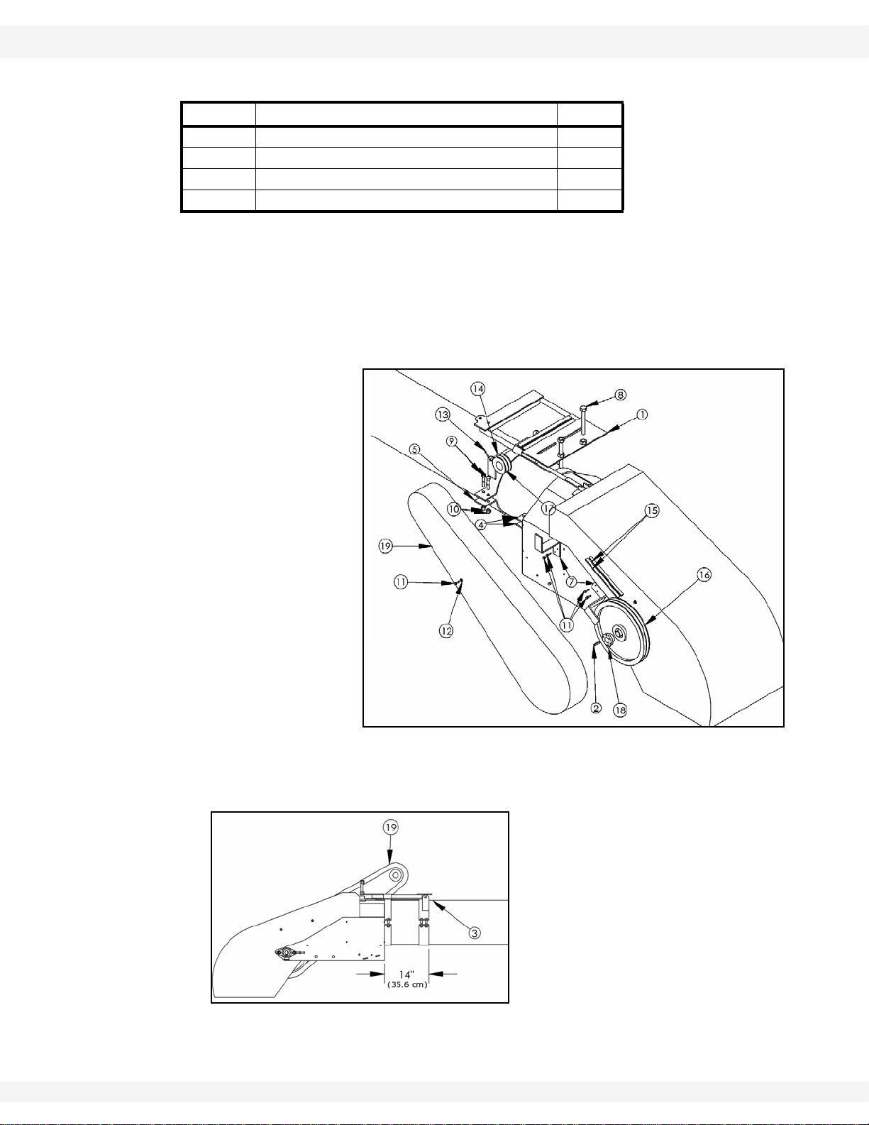
4.1. ELECTRIC TOP DRIVE ASSEMBLY
Note: Refer to Table 4.1 for the quantity of each component used, and Figure 4.1 and
4.2 for illustrations of the assembly of the electric drive kit.
1. Install two u-clamps (4) with two 1/2” x 2-1/2” bolts (9) and locknuts (10) as
seen in Figure 4.1 and Figure 4.2.
2. Position the electric motor clamp (6) on top of the tube and fasten with a 3” u-
clamp (5), 1/2” x 2-1/2” bolts (9), and locknuts (10). Ensure it is level before
crimping to tube.
3. Install the motor mount plate (1) with the motor mount pin (14) and a 3/16” x
1-1/2” cotter pin (13). Secure by spreading cotter pin.
4. Position electric motor (not shown) on motor mount plate (1) and fasten with
the appropriate bolts and locknuts. Leave bolts finger tight for now.
5. Install a key in the motor shaft. Mount drive pulley (17) so the hub is flush
with the end of the shaft, then secure.
6. Install a key (2) in the drive roller shaft. Mount driven pulley (16) so the hub is
flush with the end of the shaft, then secure.
7. Use a straight edge to align the pulleys.
8. Tighten motor base bolts.
9. Install drive belts (15) and set belt tension by adjusting the 3/4” x 6” tap bolt
(8).
Warning: Before continuing, please read the safety information relevant to this section in the
safety section of this manual. Failure to follow the safety instructions can result in serious
injury, death, or property damage.
Table 4.1
ITEM DESCRIPTION QTY
1Motor Mount Plate 1
2Key 1/4” x 1-1/2” 1
3Spout Assembly 1
42" U-Clamp 2
53" U-Clamp 1
6Electric Motor Clamp 1
7Guard Mount 2
8Bolt Tap 3/4” x 6” 1
9Bolt Hex 1/2” x 2-1/2” GR8 6
10 Nut Nylock 1/2” 6
11 Self-Tapping Screw 1” 10
12 Flat Washer 1/4” USS Plated 4
13 Cotter Pin 3/16” x 1-1/2” 1
14 Motor Mount Pin 1
15 Belt B 105 2
4. ASSEMBLY BATCO - PITSTOP
4.1. ELECTRIC TOP DRIVE ASSEMBLY 2500 SERIES
20 P1511025 R0
Note: Belts should deflect 1/2” to 3/4” when pushed on with a 5 lb (2.3 kg) force. Check
frequently during the first 10 hours of operation to maintain proper tension.
10. Mount a keyed shaft guard (not shown) over the left drive roller shaft with a
1/4” x 1/2” bolt, 1/4” lock washer, and a 1/4” flat washer.
Note: Be sure the shaft guard is seated against the bearing. It may be necessary to tap
cover with a hammer for it to seat properly.
11. Attach safety sign
on the plastic
pulley guard and
on spout plate.
12. Hold plastic pulley
guard (19) over
the belt and mark
suitable mounting
bracket locations.
13. Place mounting
brackets (7) on
plastic guard (19)
and drill holes
through the
bracket and
guard. Attach the
brackets (7) to the
spout with self-
tapping screws
(11).
14. Mount plastic guard (19) to the machine with self-tapping screws (11) and
1/4” flat washers (12) as shown in Figure 4.1.
Figure 4.2
16 Pulley 2BK140H 1
17 Pulley 2BK34H 1
18 Bushing H 1.25 1
19 PitStop Plastic Pulley Guard 1
Table 4.1
ITEM DESCRIPTION QTY
Figure 4.1
This manual suits for next models
1
Table of contents


