Baumer Hübner EExGP 02-TG 74 d Service manual
EExGP 0,2 • TG 74 d
Tachogenerator mit Ex-Schutzzulassung
Tachogenerator with EX approval
Montage- und Betriebsanleitung
Mounting and operating instructions
MB053 - 11055655 Baumer_EEXGP02-TG74D_II_DE-EN (18A1)

Baumer_EEXGP02-TG74D_II_DE-EN (18A1) MB053 - 11055655
Inhaltsverzeichnis
Inhaltsverzeichnis
1Allgemeine Hinweise ................................................................................................................................................1
2Betrieb in explosionsgefährdeten Bereichen .........................................................................................3
3Sicherheitshinweise .................................................................................................................................................5
4Vorbereitung ..................................................................................................................................................................7
4.1 Lieferumfang .....................................................................................................................................................7
4.2 Zur Montage erforderlich (nicht im Lieferumfang enthalten) ...................................................8
4.3 Erforderliches Werkzeug (nicht im Lieferumfang enthalten) ...................................................8
5Montage .............................................................................................................................................................................9
5.1 Schritt 1 ...............................................................................................................................................................9
5.2 Schritt 2 ...............................................................................................................................................................9
5.3 Schritt 3 ............................................................................................................................................................ 10
5.4 Schritt 4 ............................................................................................................................................................ 10
5.5 Schritt 5 ............................................................................................................................................................ 10
5.6 Schritt 6 .............................................................................................................................................................11
5.7 Montagehinweis ........................................................................................................................................... 12
5.8 Maximal zulässige Montagefehler unter Verwendung der
Baumer Hübner Federscheibenkupplung K 35 ........................................................................... 13
6Abmessung .................................................................................................................................................................. 14
7Elektrischer Anschluss ....................................................................................................................................... 14
7.1 Klemmenbelegung ...................................................................................................................................... 14
8Betrieb und Wartung ............................................................................................................................................. 15
8.1 Austausch der Kohlebürsten ................................................................................................................. 15
9Demontage ................................................................................................................................................................... 16
9.1 Schritt 1 ............................................................................................................................................................ 16
9.2 Schritt 2 ............................................................................................................................................................ 16
9.3 Schritt 3 .............................................................................................................................................................17
9.4 Schritt 4 .............................................................................................................................................................17
9.5 Schritt 5 .............................................................................................................................................................17
10 Zubehör .......................................................................................................................................................................... 18
11 Technische Daten .................................................................................................................................................... 19
11.1 Technische Daten - elektrisch .............................................................................................................. 19
11.2 Technische Daten - mechanisch ......................................................................................................... 19
11.3 Daten nach Typ ............................................................................................................................................. 20
11.4 Ersatzschaltbild ............................................................................................................................................ 20
12 EU-Konformitätserklärung ................................................................................................................................ 23

MB053 - 11055655 Baumer_EEXGP02-TG74D_II_DE-EN (18A1)
Table of contents
Table of contents
1General notes ................................................................................................................................................................2
2Operation in potentially explosive environments .................................................................................4
3Security indications ..................................................................................................................................................6
4Preparation .....................................................................................................................................................................7
4.1 Scope of delivery ............................................................................................................................................7
4.2 Required for mounting (not included in scope of delivery) .......................................................8
4.3 Required tools (not included in scope of delivery) ........................................................................8
5Mounting ...........................................................................................................................................................................9
5.1 Step 1 ...................................................................................................................................................................9
5.2 Step 2 ...................................................................................................................................................................9
5.3 Step 3 ................................................................................................................................................................ 10
5.4 Step 4 ................................................................................................................................................................ 10
5.5 Step 5 ................................................................................................................................................................ 10
5.6 Step 6 .................................................................................................................................................................11
5.7 Mounting instruction .................................................................................................................................. 12
5.8 Maximum permissible mounting tolerance when the
Baumer Hübner K 35 spring disk coupling is used .................................................................... 13
6Dimension ..................................................................................................................................................................... 14
7Electrical connection ............................................................................................................................................ 14
7.1 Terminal assignment ................................................................................................................................. 14
8Operation and maintenance ............................................................................................................................. 15
8.1 Replace of the carbon brushes ............................................................................................................ 15
9Dismounting ................................................................................................................................................................ 16
9.1 Step 1 ................................................................................................................................................................ 16
9.2 Step 2 ................................................................................................................................................................ 16
9.3 Step 3 ................................................................................................................................................................ 17
9.4 Step 4 ................................................................................................................................................................ 17
9.5 Step 5 ................................................................................................................................................................ 17
10 Accessories ................................................................................................................................................................. 18
11 Technical data ............................................................................................................................................................ 21
11.1 Technical data - electrical ratings ....................................................................................................... 21
11.2 Technical data - mechanical design .................................................................................................. 21
11.3 Type data ......................................................................................................................................................... 22
11.4 Replacement switching diagram ......................................................................................................... 22
12 EU Declaration of Conformity ......................................................................................................................... 23
1Baumer_EEXGP02-TG74D_II_DE-EN (18A1) MB053 - 11055655
1Allgemeine Hinweise
1Allgemeine Hinweise
1.1 Zeichenerklärung:
Gefahr
Warnung bei möglichen Gefahren
Hinweis zur Beachtung
Hinweis zur Gewährleistung eines einwandfreien Betriebes des Gerätes
i
Information
Empfehlung für die Gerätehandhabung
1.2 Der Tachogenerator mit Ex-Schutzzulassung EExGP 0,2 • TG 74 d ist ein generatorisch
arbeitendes Präzisions-Drehzahlmessgerät, das mit Sorgfalt nur von technisch qualiziertem
Personal gehandhabt werden darf.
1.3 Die zu erwartende Lebensdauer des Gerätes hängt von den Kugellagern ab, die mit einer
Dauerschmierung ausgestattet sind.
1.4 Kohlebürsten haben eine zu erwartende Lebensdauer, die vom Stromdurchgang abhängt
und in der Regel der Kugellagerlebensdauer entspricht. Ein Wechsel der Kohlebürsten ist nur
vorsorglich erforderlich.
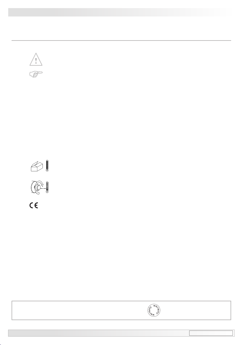
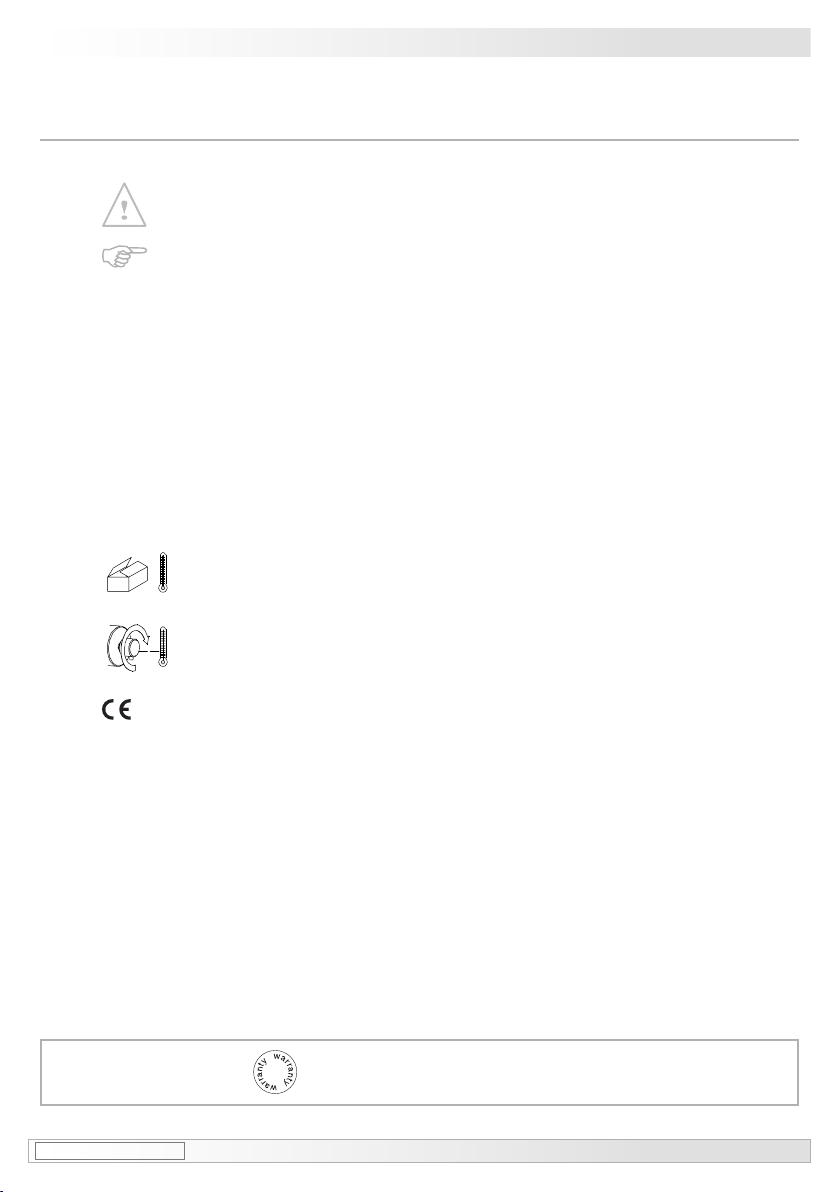
1.5 Der Lagertemperaturbereich des Gerätes liegt zwischen -15 °C bis +70 °C.
1.6 Der maximale Umgebungstemperaturbereich für den Einsatz des Gerätes im
Ex-Bereich 2 G beträgt -20 °C bis +55 °C.
1.7 EU-Konformitätserklärung gemäß den europäischen Richtlinien.
1.8 Wir gewähren 2 Jahre Gewährleistung im Rahmen der Bedingungen des Zentralverbandes der
Elektroindustrie (ZVEI).
1.9 Wartungsarbeiten sind nicht erforderlich. Reparaturen sind ausschließlich vom Hersteller
durchzuführen. Am Gerät dürfen keine Veränderungen vorgenommen werden.
Bei Zuwiderhandlung erlischt die Ex-Zulassung.
1.10 Bei Rückfragen bzw. Nachlieferungen sind die auf dem Typenschild des Gerätes angege-
benen Daten, insbesondere Typ und Seriennummer, unbedingt anzugeben.
1.11 Alle Bestandteile des Gerätes sind nach länderspezischen Vorschriften zu entsorgen.
i
Achtung!
Beschädigung des auf dem Gerät bendlichen Siegels führt zu Gewährleistungsver-
lust.
MB053 - 11055655 Baumer_EEXGP02-TG74D_II_DE-EN (18A1) 2
General notes 1
1General notes
1.1 Symbol guide:
Danger
Warnings of possible danger
General information for attention
Informations to ensure correct device operation
i
Information
Recommendation for device handling
1.2 The tachogenerator with EX approval EExGP 0,2 • TG 74 d is a generator-based working
precision rotary measurement device which must be handled with care by skilled
personnel only.
1.3 The expected service life of the device depends on the ball bearings, which are equipped with
a permanent lubrication.
1.4 The expected service life of carbon brushes depends on the electrical current and is usually
consistent with the service life of the ball bearings. Replacement of the carbon brushes is only a
recommended precaution.
1.5 The storage temperature range of the device is between -15 °C and +70 °C.
1.6 In Ex areas 2 G the device must only be used within the ambient temperature range
from -20 °C to +55 °C.
1.7 EU Declaration of Conformity meeting to the European Directives.
1.8 We grant a 2-year warranty in accordance with the regulations of the ZVEI (Central Association
of the German Electrical Industry).
1.9 Maintenance work is not necessary. Repair work must be carried out by the manufacturer.
Alterations of the device are not permitted.
Contravention invalidates the EX approval.
1.10 In the event of queries or subsequent deliveries, the data on the device type label must be
quoted, especially the type designation and the serial number.
1.11 Device components are to be disposed of according to the regulations prevailing in the
respective country.
i
Warning!
Damaging the seal on the device invalidates warranty.

3Baumer_EEXGP02-TG74D_II_DE-EN (18A1) MB053 - 11055655
2Betrieb in explosionsgefährdeten Bereichen
2Betrieb in explosionsgefährdeten Bereichen
2.1 Das Gerät entspricht der Richtlinie 2014/34/EU für explosionsgefährdete Bereiche.
Der Einsatz ist gemäß der Gerätekategorie 2 G (Ex-Atmosphäre Gas) zulässig.
Gerätekategorie 2 G: - Ex-Kennzeichnung: II 2 G Ex db eb IIC T6 Gb
- Normenkonformität: EN 60079-0:2012 + A11:2013
Allgemeine Bestimmungen
EN 60079-1:2014
Druckfeste Kapselung „d“
EN 60079-7:2015
Erhöhte Sicherheit „e“
- Zündschutzart: db eb
- Temperaturklasse: T6
- Gerätegruppe: II
- Explosionsgruppe: IIC
- Geräteschutzniveau: Gb
Der Einsatz in Bereiche der Kategorie 3 G sind ebenso zulässig. Der Einsatz in anderen explosi-
onsgefährdeten Bereichen ist nicht zulässig.
EU-Baumusterprüfbescheinigung auf Anfrage: TÜV NORD CERT Nr. TÜV 03 ATEX 2201 X
2.2 Der maximale Umgebungstemperaturbereich für den Einsatz des Gerätes im Ex-Bereich 2G
beträgt -20 °C bis +55 °C.
2.3 Eine gegebenenfalls in der sonstigen technischen Dokumentation aufgeführte UL-Listung gilt
nicht für den Einsatz im Ex-Bereich.
2.4 Das Gerät darf nur in Betrieb genommen werden, wenn ...
– die Angaben auf dem Typenschild des Gerätes mit dem zulässigen Ex-Einsatzbereich vor
Ort übereinstimmen (Gerätegruppe, Kategorie, Zone, Temperaturklasse bzw. maximale
Oberächentemperatur),
– die Angaben auf dem Typenschild des Gerätes mit dem Spannungsnetz übereinstimmen,
– das Gerät unbeschädigt ist (keine Schäden durch Transport und Lagerung) und
– sichergestellt ist, dass keine explosionsfähige Atmosphäre, Öle, Säure, Gase, Dämpfe,
Strahlungen etc. bei der Montage vorhanden sind.
2.5 An Betriebsmittel, die in explosionsgefährdeten Bereichen eingesetzt werden, darf keine Verän-
derung vorgenommen werden. Reparaturen an explosionsgeschützten Betriebsmittel dürfen
ausschließlich vom Hersteller durchgeführt werden.
Bei Zuwiderhandlung erlischt die Ex-Zulassung.
2.6 Bei der Montage und Inbetriebnahme ist die Norm EN 60079-14 zu beachten.
Das Gerät ist entsprechend den Angaben in der Montage- und Betriebsanleitung zu
betreiben. Die für die Verwendung bzw. den geplanten Einsatzzweck zutreffenden
Gesetze, Richtlinien und Normen sind zu beachten.

MB053 - 11055655 Baumer_EEXGP02-TG74D_II_DE-EN (18A1) 4
Operation in potentially explosive environments 2
2Operation in potentially explosive environments
2.1 The device complies with the directive 2014/34/EU for potentionally explosive atmospheres.
It can be used in accordance with equipment category 2 G (explosive gas atmosphere).
Equipment category 2 G: - Ex labeling: II 2 G Ex db eb IIC T6 Gb
- Conforms to standard: EN 60079-0:2012 + A11:2013
Generaldenation
EN 60079-1:2014
Explosion proof enclosure „d“
EN 60079-7:2015
Increased safety „e“
- Type of protection: db eb
- Temperature class: T6
- Group of equipment: II
- Explosive gas group: IIC
- Device protection level: Gb
Operation in explosive atmospheres of category 3 G is also permissible. The operation in other
explosive atmospheres is not permissible.
EUtypeexaminationcerticateondemand:TÜV NORD CERT Nr. TÜV 03 ATEX 2201 X
2.2 In Ex areas 2Gthe device must only be used within the ambient temperature range from -20
°C to +55 °C.
2.3 Any UL listing that may be quoted in any other technical documentation does not apply to use
in the Ex area.
2.4 Operation of the device is only permissible when ...
– the details on the type label of the device match the on-site conditions for the permissible
Ex area in use (group of equipment, equipment category, zone, temperature class or maxi-
mum surface temperature),
– the details on the type label of the device match the electrical supply network,
– the device is undamaged (no damage resulting from transport or storage), and
– it has been checked that there is no explosive atmosphere, oils, acids, gases, vapors,
radiation etc. present when mounting.
2.5 It is not permissible to make any alteration to equipment that is used in potentially explosive en-
vironments. Repairs of explosion-protected equipment may only be carried out by the manufac-
turer.
Contravention invalidates the EX approval.
2.6 Attend the norm EN 60079-14 during mount and operation.
The device must be operated in accordance with the stipulations of the mounting and
operating instructions. The relevant laws, regulations and standards for the planned
application must be observed.

5Baumer_EEXGP02-TG74D_II_DE-EN (18A1) MB053 - 11055655
3Sicherheitshinweise
3Sicherheitshinweise
3.1 Verletzungsgefahr durch rotierende Wellen
Haare und Kleidungsstücke können von rotierenden Wellen erfasst werden.
• Vor allen Arbeiten alle Betriebsspannungen ausschalten und Maschinen stillsetzen.
3.2 Zerstörungsgefahr durch mechanische Überlastung
Eine starre Befestigung kann zu Überlastung durch Zwangskräfte führen.
• Die Beweglichkeit des Gerätes niemals einschränken.
Unbedingt die Montagehinweise beachten.
• Die vorgegebenen Abstände und/oder Winkel unbedingt einhalten.
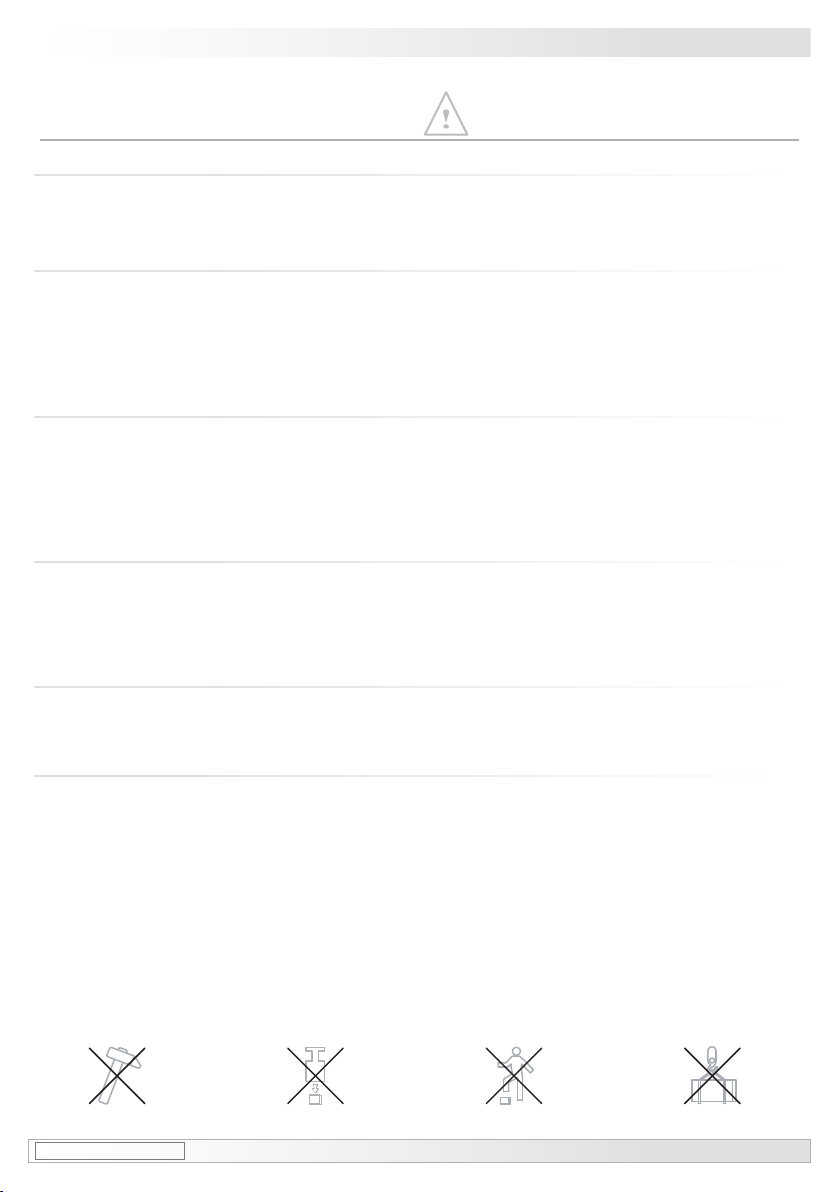
3.3 Zerstörungsgefahr durch mechanischen Schock
Starke Erschütterungen, z. B. Hammerschläge, können zur Zerstörung des Gerätes führen.
• Niemals Gewalt anwenden.
Bei sachgemäßer Montage lässt sich alles leichtgängig zusammenfügen.
• Für die Demontage geeignetes Abziehwerkzeug benutzen.
3.4 Zerstörungsgefahr durch Verschmutzung
Schmutz kann im Gerät zu dessen Beschädigung führen.
• Während aller Arbeiten am Gerät auf absolute Sauberkeit achten.
• Niemals Öl oder Fett in das Innere des Gerätes gelangen lassen.
3.5 Zerstörungsgefahr durch klebende Flüssigkeiten
Klebende Flüssigkeiten können die Magnete und Kohlebürsten beschädigen. Die Demontage
eines mit der Achse verklebten Gerätes kann zu dessen Zerstörung führen.
3.6 Explosionsgefahr
Das Gerät darf in explosiongefährdeten Bereichen der Gerätekategorie 2 G (Zone 1) und 3 G
eingesetzt werden. Der Betrieb in anderen explosionsgefährdeten Bereichen ist nicht zulässig.
MB053 - 11055655 Baumer_EEXGP02-TG74D_II_DE-EN (18A1) 6
Security indications 3
3Security indications
3.1 Risk of injury due to rotating shafts
Hair and clothes may become tangled in rotating shafts.
• Before all work switch off all voltage supplies and ensure machinery is stationary.
3.2 Risk of destruction due to mechanical overload
Rigid mounting may give rise to constraining forces.
• Never restrict the freedom of movement of the device.
The mounting instructions must be followed.
• Itisessentialthatthespeciedclearancesand/oranglesareobserved.
3.3 Risk of destruction due to mechanical shock
Violent shocks, e. g. due to hammer impacts, can lead to the destruction of the device.
• Never use force.
Mounting is simple when correct procedure is followed.
• Use suitable puller for dismounting.
3.4 Risk of destruction due to contamination
Dirt penetrating inside the device can damage the device.
• Absolute cleanliness must be maintained when carrying out any work on the device.
• Never allow lubricants to penetrate the device.
3.5 Risk of destruction due to adhesive uids
Adhesiveuidscandamagethemagnetsandthecarbonbrushes.Dismountingadevice,se-
cured to a shaft by adhesive may lead to the destruction of the device.
3.6 Explosion risk
You can use the device in areas with explosive atmospheres of equipment category 2 G (zone 1)
and 3 G. The operation in other explosive atmospheres is not permissible.

7Baumer_EEXGP02-TG74D_II_DE-EN (18A1) MB053 - 11055655
1Gehäuse
2EURO-Flansch B10
3Vollwelle mit Passfeder
4Klemmenkastendeckel
5Zylinderschraube, M4x30 mm, ISO 4762
6Federring 4, DIN 7980
7Kabelverschraubung M16x1,5 mm
für Kabel ø5...9 mm
8Anschlussklemmen,
siehe Abschnitt 5.6 und 7.1.
9Erdungsanschluss
1Housing
2EUROangeB10
3Solid shaft with key
4Terminal box cover
5Cylinder screw M4x30 mm, ISO 4762
6Spring washer 4, DIN 7980
7Cable gland M16x1.5 mm
for cable ø5...9 mm
8Connecting terminal,
see section 5.6 and 7.1.
9Earth connection
4Vorbereitung
4.1 Lieferumfang
4Preparation
4.1 Scope of delivery
4Vorbereitung/Preparation
12
3
4
56
7
899

MB053 - 11055655 Baumer_EEXGP02-TG74D_II_DE-EN (18A1) 8
Vorbereitung/Preparation 4
4.2 Zur Montage erforderlich
(nicht im Lieferumfang enthalten)
4.2 Required for mounting
(not included in scope of delivery)
10
11 12 13
10 Anbauvorrichtung, kundenspezisch
11 Befestigungsschraube für Anbauvorrichtung
ISO 4017, M6x16 mm
12 Federscheibenkupplung K 35,
als Zubehör erhältlich, siehe Abschnitt 5.5
13 Anschlusskabel
10 Installationtting,customized
11 FixingscrewforinstallationttingISO4017,
M6x16 mm
12 Spring disk coupling K 35,
available as accessory, see section 5.5
13 Connecting cable
4.3 Erforderliches Werkzeug
(nicht im Lieferumfang enthalten)
4.3 Required tools
(not included in scope of delivery)
12x
2,5 und 3 mm
10 und 17 mm
14 Werkzeugset als Zubehör erhältlich,
Bestellnummer: 11068265
2.5 and 3 mm
10 and 17 mm
14 Tool kit available as accessory,
order number: 11068265
5Montage / Mounting
9Baumer_EEXGP02-TG74D_II_DE-EN (18A1) MB053 - 11055655
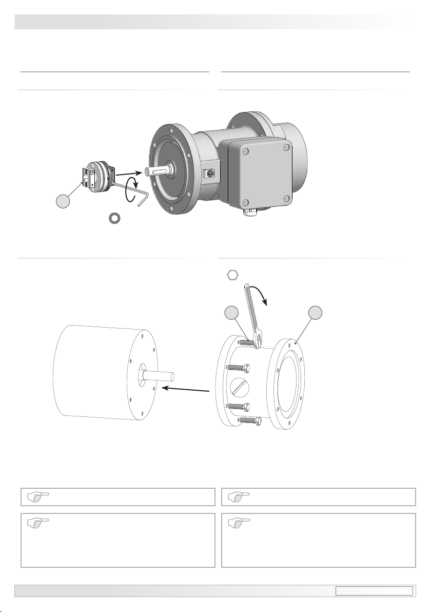
5Montage
5.1 Schritt 1
5Mounting
5.1 Step 1
Zul. Anzugsmoment:
Max. tightening torque:
Mt= 100 Ncm
5.2 Schritt 2 5.2 Step 2
Die Antriebswelle sollte einen
möglichst kleinen Rundlauffehler
aufweisen. Rundlauffehler verursa-
chen Vibrationen, die die Lebensdauer
des Gerätes verkürzen können.
The drive shaft should have as less
runout as possible. Runouts can cause
vibrations, which can shorten the
service life of the device.
12 *
1011 **
*Siehe Seite 8
See page 8
Antriebswelle einfetten. Lubricate drive shaft.
2.5 mm
10 mm

MB053 - 11055655 Baumer_EEXGP02-TG74D_II_DE-EN (18A1) 10
Montage / Mounting 5
5.4 Schritt 4 5.4 Step 4
5.3 Schritt 3 5.3 Step 3
5.5 Schritt 5 5.5 Step 5
Zul. Anzugsmoment:
Max. tightening torque:
Mt= 2...3 Nm
12 *
2*11 *
564 ***
7*
* Siehe Seite 7 oder 8
See page 7 or 8
2.5 mm
3 mm
17 mm
10 mm

5Montage / Mounting
11 Baumer_EEXGP02-TG74D_II_DE-EN (18A1) MB053 - 11055655
5.6 Schritt 6 5.6 Step 6
Ansicht X
siehe Abschnitt 7.1.
View X
see section 7.1.
564 ***
8*
7*
13 *
Zur Gewährleistung der angegebenen
Schutzart sind nur geeignete Kabel-
durchmesser zu verwenden.
To ensure the specied protection of
the device the correct cable diameter
must be used.
ø5...9 mm
* Siehe Seite 7 oder 8
See page 7 or 8
Zul. Anzugsmoment:
Max. tightening torque:
Mt= 2...3 Nm
Vor der Montage des Klemmenkasten-
deckels prüfen, ob die Klemmenka-
stendeckeldichtung unbeschädigt ist.
Check that the seal of the terminal box
is not damaged before mounting the
terminal box.
3 mm
17 mm
MB053 - 11055655 Baumer_EEXGP02-TG74D_II_DE-EN (18A1) 12
Montage / Mounting 5
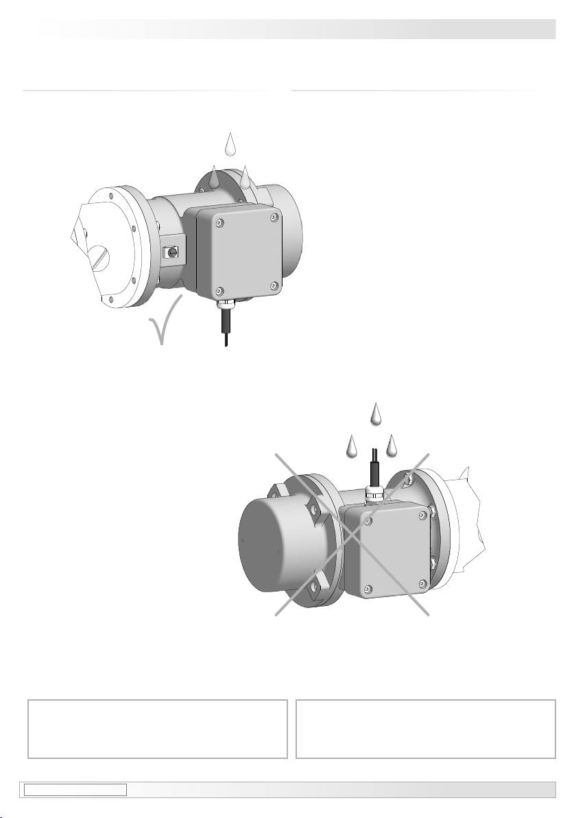
5.7 Montagehinweis 5.7 Mounting instruction
i
Wir empfehlen, das Gerät so zu
montieren, dass der Kabelanschluss
keinem direkten Wassereintritt
ausgesetzt ist.
i
It is recommended to mount the device
with cable connection facing down-
ward and being not exposed to water.
5Montage / Mounting
13 Baumer_EEXGP02-TG74D_II_DE-EN (18A1) MB053 - 11055655
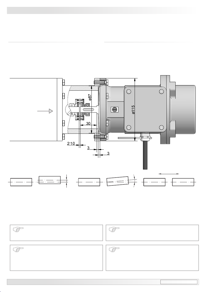
Fmax= 10N
5.8 Maximal zulässige Montagefehler
unter Verwendung der Baumer Hübner
Federscheibenkupplung K 35
Geräte mit Vollwelle sollten unter Verwen-
dung der Baumer Hübner Federschei-
benkupplung K 35 (Zubehör) angetrieben
werden, die sich ohne axialen Druck auf
die Welle schieben lässt.
5.8 Maximum permissible mounting toler-
ance when the Baumer Hübner K 35
spring disk coupling is used
Devices with a solid shaft should be
driven through the Baumer Hübner K 35
spring disk coupling (accessory), that can
be pushed onto the shaft without axial
loading.
Zulässiger Parallelversatz
Admissible parallel misalignment
Zulässiger Winkelfehler
Admissible angular error
Zulässige Axialbewegung
Admissible axial movement
±0.2 (±0.05*)
±1°
*Mit isolierender Kunststoffnabe
With insulated hub
±0.7 (±0.3*)
Die Montage an den Antrieb muss mit
möglichst geringem Winkelfehler und
Parallelversatz erfolgen.
Das harte Aufschlagen von Kupp-
lungsteilen auf die Welle ist wegen der
Gefahr von Kugellagerbeschädi-
gungen nicht zulässig.
The device must be mounted on the
drive with the least possible angular
error and parallel misalignment.
Coupling components must not be
driven onto the shaft with improper
force (e. g. hammer impacts), because
of the risk of damaging the ball
bearings.
Alle Abmessungen in Millimeter (wenn nicht anders angegeben)
All dimensions in millimeters (unless otherwise stated)

MB053 - 11055655 Baumer_EEXGP02-TG74D_II_DE-EN (18A1) 14
Abmessung - Elektrischer Anschluss/Dimension-Electricalconnection 6-7
6Abmessung
89000 (TG 74 d), 89005 (EEx GP 0,2)
6Dimension
89000(TG74d),89005(EExGP0,2)
7Elektrischer Anschluss
7.1 Klemmenbelegung
Polarität bei positiver Drehrichtung, siehe
Abschnitt 6.
7Electrical connection
7.1 Terminal assignment
Polarityforpositiverotatingdirection,see
section 6.
Drehrichtung positiv
Positiverotatingdirection
Ansicht X
Anschlussklemmen
siehe Abschnitt 5.6.
View X
Connecting terminal
see section 5.6.
ød L1 L2
EEx GP 0,2 11 12.6 4
TG 74 d 14 16.1 5
A1:
A2:
Alle Abmessungen in Millimeter (wenn nicht anders angegeben)
All dimensions in millimeters (unless otherwise stated)
15 Baumer_EEXGP02-TG74D_II_DE-EN (18A1) MB053 - 11055655
8Betrieb und Wartung/Operationandmaintenance
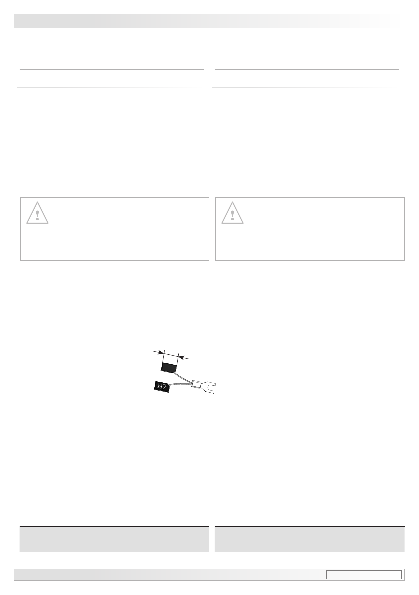
8Betrieb und Wartung
8.1 Austausch der Kohlebürsten
Bei Erreichen der minimalen Kohle-
bürstenlänge (L) von 5,3 mm sollten die
Kohlebürsten ausgewechselt sowie der
Kommutatorraum mit trockener Pressluft
ausgeblasen werden, damit weiterhin ein
einwandfreier Betrieb gewährleistet ist.
8Operation and maintenance
8.1 Replace of the carbon brushes
When the minimum carbon brush length
(L) of 5.3 mm is reached , the carbon
brushes should be replaced and the com-
mutator area should be cleaned with dry
compressed air in order to ensure perfect
operation.
Kohlebürsten als Zubehör erhältlich:
Bestellnummer 11076778
Carbon brushes available as accessory:
Order number 11076778
Verlust der Ex-Zulassung bei Öffnen
des Gerätes!
Die Kohlebürsten dürfen nur vom Herstel-
ler ausgetauscht werden, da ansonsten
die Ex-Zulassung nicht mehr gewährlei-
stet wird.
Forfeiture of the Ex protection when
opening the device!
Replace of the carbon brushes must be
carried out by the manufacturer otherwise
you lost the warranty for the Ex protection
of the unit.
L
Kohlebürste
Carbon brush

MB053 - 11055655 Baumer_EEXGP02-TG74D_II_DE-EN (18A1) 16
Demontage/Dismounting 9
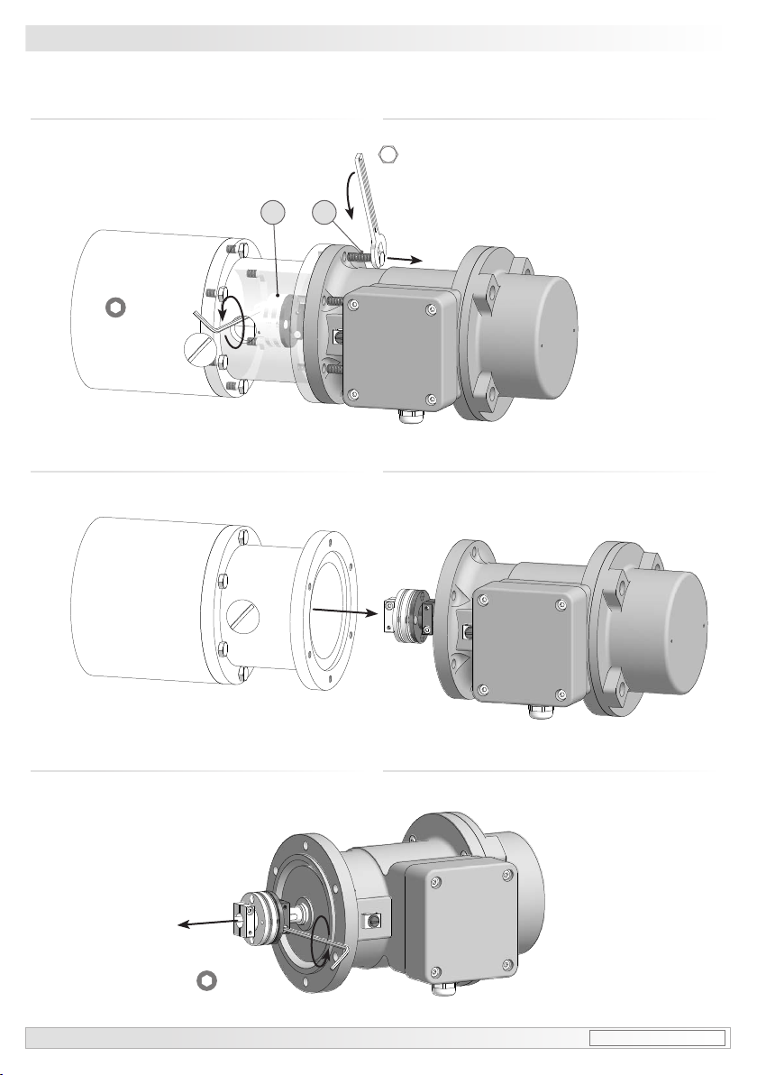
9.2 Schritt 2 9.2 Step 2
9Demontage
9.1 Schritt 1
9Dismounting
9.1 Step 1
564 ***
7*
8*
13 *
* Siehe Seite 7 oder 8
See page 7 or 8
3 mm
17 mm
17 Baumer_EEXGP02-TG74D_II_DE-EN (18A1) MB053 - 11055655
9Demontage/Dismounting
9.4 Schritt 4 9.4 Step 4
9.5 Schritt 5 9.5 Step 5
*Siehe Seite 8
See page 8
9.3 Schritt 3 9.3 Step 3
12 *11 *
10 mm
2.5 mm
2.5 mm
Table of contents
Other Baumer Hübner Industrial Equipment manuals


