Baumer Hübner POG 90 User manual

POG 90 + FSL
Kombination
Combination
MB154.1 pog90-fsl_mb (08A1)
Montage- und Betriebsanleitung
Installation and operating instructions

pog90-fsl_mb (08A1) MB154.1
4Montage / MountingInhaltsverzeichnis
Inhaltsverzeichnis
1Allgemeine Hinweise ...................................................................................................................................................1
2Sicherheitshinweise .....................................................................................................................................................3
3Vorbereitung ......................................................................................................................................................................5
3.1 Lieferumfang ........................................................................................................................................................5
3.2 zur Montage erforderlich bzw. empfohlen (nicht im Lieferumfang enthalten) ....................6
4Montage ................................................................................................................................................................................7
4.1 Schritt 1 ...................................................................................................................................................................7
4.2 Schritt 2 ...................................................................................................................................................................7
4.3 Schritt 3 ...................................................................................................................................................................8
4.4 Schritt 4 ...................................................................................................................................................................8
4.5 Max. zulässige Anbaufehler unter Verwendung
der Baumer Hübner Federscheiben-Kupplung K 35 .......................................................................9
4.6 Anbauhinweis .................................................................................................................................................... 10
4.7 Schritt 5 - Klemmenkasten POG 90 ...................................................................................................... 10
4.8 Schritt 6 - Klemmenkasten POG 90 .......................................................................................................11
4.9 Schritt 7 - Klemmenkasten POG 90 .......................................................................................................11
4.10 Schritt 8 - Klemmenkasten POG 90 ...................................................................................................... 12
4.11 Schritt 9 - Klemmenkasten POG 90 ...................................................................................................... 12
4.12 Schritt 10 - Klemmenkasten POG 90 ................................................................................................... 13
4.13 Schritt 11 - Klemmenkasten FSL ............................................................................................................ 13
4.14 Schritt 12 - Klemmenkasten FSL ............................................................................................................ 14
5Maßzeichnung ............................................................................................................................................................... 14
6Elektrischer Anschluss .......................................................................................................................................... 15
6.1 Klemmenbelegung POG 90 ...................................................................................................................... 15
6.2 Ausgangssignale POG 90 .......................................................................................................................... 16
6.3 Kabel HEK 8 (Zubehör) ............................................................................................................................... 16
6.4 Klemmenbelegung FSL ............................................................................................................................... 17
7Demontage ...................................................................................................................................................................... 17
8Zubehör .............................................................................................................................................................................. 20
9Technische Daten ....................................................................................................................................................... 21
9.1 Technische Daten - Kombination POG 90 + FSL .......................................................................... 21
9.2 Technische Daten - Drehimpulsgeber POG 90 ............................................................................... 21
9.3 Technische Daten - Fliehkraftschalter FSL ....................................................................................... 22

MB154.1 pog90-fsl_mb (08A1)
Montage / Mounting 4
Table of contents
Table of contents
1General notes ...................................................................................................................................................................2
2Security indications .....................................................................................................................................................4
3Preparation .........................................................................................................................................................................5
3.1 Scope of delivery ...............................................................................................................................................5
3.2 required resp. recommended for mounting (not included in scope of delivery) ................6
4Mounting ..............................................................................................................................................................................7
4.1 Step 1 .......................................................................................................................................................................7
4.2 Step 2 .......................................................................................................................................................................7
4.3 Step 3 .......................................................................................................................................................................8
4.4 Step 4 .......................................................................................................................................................................8
4.5 Max. permissible mounting tolerance
when the Baumer Hübner K 35 spring disk coupling is used .....................................................9
4.6 Mounting instruction ...................................................................................................................................... 10
4.7 Step 5 - Terminal box POG 90 ................................................................................................................. 10
4.8 Step 6 - Terminal box POG 90 ..................................................................................................................11
4.9 Step 7 - Terminal box POG 90 ..................................................................................................................11
4.10 Step 8 - Terminal box POG 90 ................................................................................................................. 12
4.11 Step 9 - Terminal box POG 90 ................................................................................................................. 12
4.12 Step 10 - Terminal box POG 90 .............................................................................................................. 13
4.13 Step 11 - Terminal box FSL ....................................................................................................................... 13
4.14 Step 12 - Terminal box FSL ....................................................................................................................... 14
5Dimension drawing .................................................................................................................................................... 14
6Electrical connection ................................................................................................................................................ 15
6.1 Terminal assignment POG 90 .................................................................................................................. 15
6.2 Output signals POG 90 ................................................................................................................................ 16
6.3 Cable HEK 8 (accessory) ........................................................................................................................... 16
6.4 Terminal assignment FSL ........................................................................................................................... 17
7Dismounting ................................................................................................................................................................... 17
8Accessories .................................................................................................................................................................... 20
9Technical data ............................................................................................................................................................... 23
9.1 Technical data - Combination POG 90 + FSL ................................................................................. 23
9.2 Technical data - Incremental encoder POG 90 ............................................................................... 23
9.3 Technical data - Mechanical centrifugal switch FSL .................................................................... 24

1 pog90-fsl_mb (08A1) MB154.1
1Allgemeine Hinweise
1Allgemeine Hinweise
1.1
Die Kombination POG 90 + FSL ist ein opto-elektronisches Präzisionsmessgerät, das mit Sorgfalt
nur von technisch qualiziertem Personal gehandhabt werden darf.
1.2 Die zu erwartende Lebensdauer des Gerätes hängt von den Kugellagern ab, die mit einer
Dauerschmierung ausgestattet sind.
1.3 Der Lagertemperaturbereich des Gerätes liegt zwischen -15 °C bis +70 °C.
1.4 Der Betriebstemperaturbereich des Gerätes liegt zwischen -20 °C bis +85 °C,
am Gehäuse gemessen.
1.5 EG Konformitätserklärung gemäß Richtlinie 89/336/EWG Artikel 10 - sowie Anhang 1
(EMV-Richtlinie).
1.6 Wir gewähren 2 Jahre Gewährleistung im Rahmen der Bedingungen des Zentralverbandes der
Elektroindustrie (ZVEI).
1.7 Reparaturen oder Wartungsarbeiten, die das Öffnen der Kombination erfordern, sind beim
Hersteller durchzuführen.
1.8 Bei Rückfragen bzw. Nachlieferungen sind die auf dem Typenschild des Gerätes angege-
benen Daten, insbesondere Typ und Seriennummer, unbedingt anzugeben.
Achtung!
Beschädigung des auf dem Gerät bendlichen Siegels führt zu
Gewährleistungsverlust.

MB154.1 pog90-fsl_mb (08A1) 2
General notes 1
1General notes
1.1 The combination POG 90 + FSL is an opto electronic precision measurement device which
must be handled with care by skilled personnel only.
1.2 The expected operating life of the device depends on the ball bearings, which are equipped with
a permanent lubrication.
1.3 The storage temperature range of the device is between -15 °C and +70 °C.
1.4 The operating temperature range of the device is between -20 °C and +85 °C,
measured at the housing.
1.5 EU Declaration of Conformity meeting Council Directive 89/336/EEC art. 10 and annex 1
(EMC Directive).
1.6 We offer a 2-year warranty in accordance with the regulations of the ZVEI (Central Association of
the German Electrical Industry).
1.7 Repair or maintenance work that requires opening the combination must be carried out by the
manufacturer.
1.8 In the event of queries or subsequent deliveries, the data on the device type label must be
quoted, especially the type designation and the serial number.
Warning!
Damaging the seal on the device invalidates warranty.

3 pog90-fsl_mb (08A1) MB154.1
2Sicherheitshinweise
2Sicherheitshinweise
2.1 Verletzungsgefahr durch rotierende Wellen
Haare und Kleidungsstücke können von rotierenden Wellen erfasst werden.
Vor allen Arbeiten alle Betriebsspannungen ausschalten und Maschinen stillsetzen.
2.2 Zerstörungsgefahr durch elektrostatische Auadung
Die elektronischen Bauteile in der Kombination sind empndlich gegen hohe Spannungen.
Steckkontakte und elektronische Komponenten nicht berühren.
Ausgangsklemmen vor Fremdspannungen schützen.
Max. Betriebsspannung nicht überschreiten.
2.3 Zerstörungsgefahr durch mechanische Überlastung
Eine starre Befestigung kann zu Überlastung durch Zwangskräfte führen.
Die Beweglichkeit der Kombination niemals einschränken. Unbedingt die Montagehinweise
beachten.
Die vorgegebenen Abstände und/oder Winkel unbedingt einhalten.
2.4 Zerstörungsgefahr durch mechanischen Schock
Starke Erschütterungen, z. B. Hammerschläge, können zur Zerstörung der Abtastung führen.
Niemals Gewalt anwenden. Bei sachgemäßer Montage lässt sich alles leichtgängig zusam-
menfügen.
Für die Demontage geeignetes Abziehwerkzeug benutzen.
2.5 Zerstörungsgefahr durch Verschmutzung
Schmutz kann in der Kombination zu Kurzschlüssen und zur Beschädigung der optischen Ab-
tastung führen.
Während aller Arbeiten am geöffneten Klemmenkasten auf absolute Sauberkeit achten.
Bei der Demontage niemals Öl oder Fett in das Innere der Kombination gelangen lassen.
2.6 Zerstörungsgefahr durch klebende Flüssigkeiten
Klebende Flüssigkeiten können die optische Abtastung und die Lager beschädigen. Die Demon-
tage einer mit der Achse verklebten Kombination kann zu dessen Zerstörung führen.
2.7 Explosionsgefahr
Die Kombination nicht in Bereichen mit explosionsgefährdeten bzw. leicht entzündlichen Mate-
rialien verwenden. Durch eventuelle Funkenbildung können diese leicht Feuer fangen und/oder
explodieren.
•
•
•
•
•
•
•
•
•
•

MB154.1 pog90-fsl_mb (08A1) 4
Security indications 2
2Security indications
2.1 Risk of injury due to rotating shafts
Hair and clothes may become tangled in rotating shafts.
Before all work switch off all operating voltages and ensure machinery is stationary.
2.2 Risk of destruction due to electrostatic charge
Electronic parts contained in the combination are sensitive to high voltages.
Do not touch plug contacts or electronic components.
Protect output terminals against external voltages.
Do not exceed max. operating voltage.
2.3 Risk of destruction due to mechanical overload
Rigid mounting may give rise to constraining forces.
Never restrict the freedom of movement of the combination. The installation instructions must
be followed.
It is essential that the specied clearances and/or angles are observed.
2.4 Risk of destruction due to mechanical shock
Violent shocks, e. g. due to hammer impacts, can lead to the destruction of the optical sensing system.
Never use force. Assembly is simple when correct procedure is followed.
Use suitable puller for disassembly.
2.5 Risk of destruction due to contamination
Dirt penetrating inside the combination can cause short circuits and damage the optical sensing
system.
Absolute cleanliness must be maintained when carrying out any work on the open terminal box.
When dismantling, never allow lubricants to penetrate the combination.
2.6 Risk of destruction due to adhesive uids
Adhesive uids can damage the optical sensing system and the bearings. Dismounting a combina-
tion, secured to a shaft by adhesive may lead to the destruction of the unit.
2.7 Explosion risk
Do not use the combination in areas with explosive and/or highly inammable materials.
They may explode and/or catch re by possible spark formation.
•
•
•
•
•
•
•
•
•
•

5 pog90-fsl_mb (08A1) MB154.1
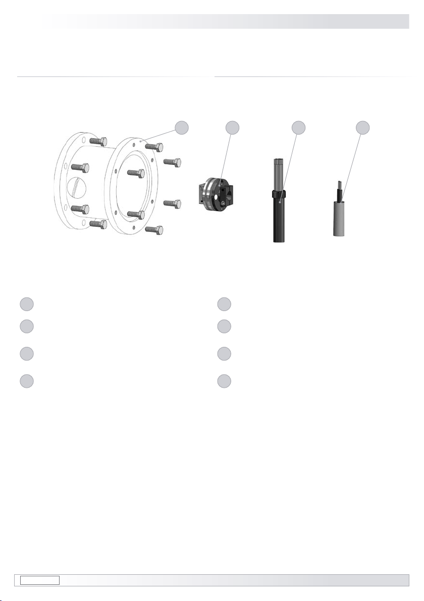
1EURO-Flansch
2Gehäuse POG 90
3Gehäuse FSL
4Vollwelle mit Passfeder
5.1
Klemmenkastendeckel POG 90
5.2
Anschlussplatine mit Anschlussklemmen POG 90
(siehe Abschnitt 4.10 und 6.1)
5.3
SUB-D Stecker am Gebergehäuse POG 90
5.4
Kabelverschraubung M20x1,5 für Kabel ∅5-13 mm
6.1
Klemmenkastendeckel FSL
6.2
Anschlussklemmen FSL (s. Abschnitt 4.13 und 6.4)
6.3
Kabelverschraubung M20x1,5 für Kabel ∅5-9 mm
1EURO ange
2Housing POG 90
3Housing FSL
4Solid shaft with key
5.1
Terminal box cover POG 90
5.2
Connecting board with connecting terminal POG 90
(see section 4.10 and 6.1)
5.3
SUB D connectors (male) on the encoder housing
5.4
Screwed gland M20x1.5 for cable ∅5-13 mm
6.1
Terminal box cover FSL
6.2
Connecting terminal FSL (s. section 4.13 and 6.4)
6.3
Screwed gland M20x1.5 for cable ∅5-9 mm
3Vorbereitung
3.1 Lieferumfang
3Preparation
3.1 Scope of delivery
3Vorbereitung / Preparation
2 3
1
4
6.2
6.1
5.3
5.2
6.3
5.4
5.1
MB154.1 pog90-fsl_mb (08A1) 6
Vorbereitung / Preparation 3
3.2
zur Montage erforderlich bzw. empfohlen
(nicht im Lieferumfang enthalten) 3.2
required resp. recommended for mounting
(not included in scope of delivery)
7
Anbauvorrichtung mit Befestigungsschrauben
8
Federscheiben-Kupplung K 35
(als Zubehör erhältlich)
9Anschlusskabel HEK 8
(als Zubehör erhältlich, siehe Abschnitt 6.3)
10
Anschlusskabel für FSL
7Installation tting with xing screws
8Spring disk coupling K 35
(available as accessory)
9Connecting cable HEK 8
(available as accessory, see section 6.3)
10
Connecting cable FSL
987
10
4Montage / Mounting
7 pog90-fsl_mb (08A1) MB154.1
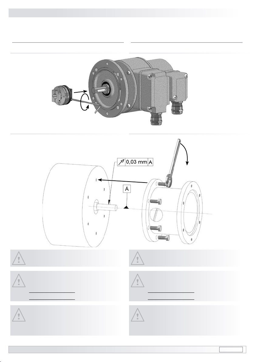
4Montage
4.1 Schritt 1
4Mounting
4.1 Step 1
4.2 Schritt 2 4.2 Step 2
zul. Anzugsmoment
Max tightening torque
Mt= 2-3 Nm
1) Sollte die Rundlaufabweichung mehr
als 0,03 mm betragen, so kontaktieren
Sie bitte unsere Hotline:
+49 (0)30/69003-111
1) If the radial run-out is more than
0.03 mm, please contact our hotline:
+49 (0)30/69003-111
Motorwelle einfetten!
Lubricate motor shaft!
1), 2)
2) Zusätzliche Einschränkungen beach-
ten, falls Federscheibenkupplung K35
mit isolierender Kunststoffnabe be-
nutzt wird (siehe Abschnitt 4.5).
2) Note additional restrictions in case
insulated hub version of the spring
disk coupling K 35 is used (see section
4.5).

MB154.1 pog90-fsl_mb (08A1) 8
Montage / Mounting 4
4.3 Schritt 3 4.3 Step 3
4.4 Schritt 4 4.4 Step 4
zul. Anzugsmoment
Max tightening torque
Mt= 2-3 Nm
4Montage / Mounting
9 pog90-fsl_mb (08A1) MB154.1
Fmax = 10N
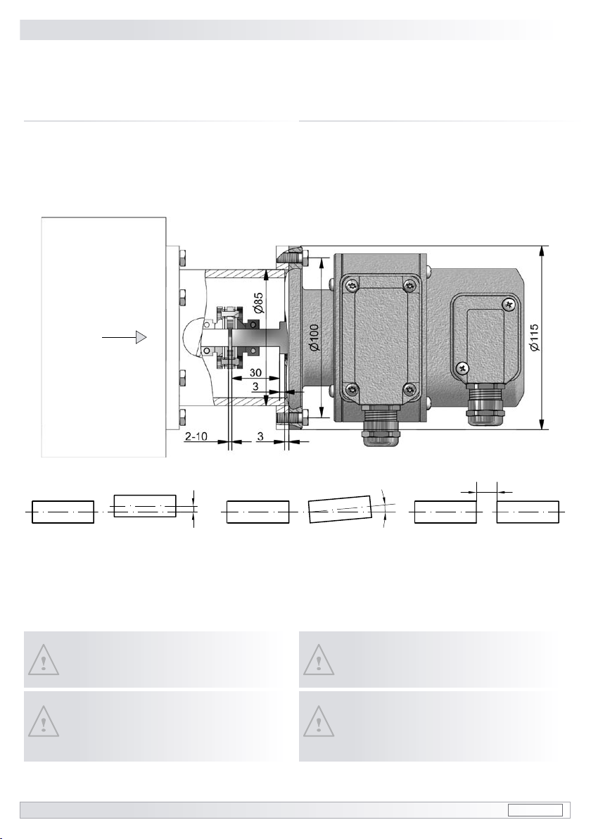
4.5 Max. zulässige Anbaufehler
unter Verwendung der Baumer Hübner
Federscheiben-Kupplung K 35
Kombinationen mit Vollwelle sollten
unter Verwendung der Baumer Hübner
Federscheiben-Kupplung K 35 (Zubehör)
angetrieben werden, die sich ohne axialen
Druck auf die Welle schieben lässt.
4.5 Max. permissible mounting tolerance
when the Baumer Hübner
K 35 spring disk coupling is used
Combinations with a solid shaft should be
driven through the Baumer Hübner K 35
spring disk coupling (accessory), that can
be pushed onto the shaft without axial
loading.
Zulässiger Parallelversatz
Admissible parallel misalignment Zulässiger Winkelfehler
Admissible angular error Zulässige Axialbewegung
Admissible axial movement
All dimensions in millimeters (unless otherwise stated)
Der Anbau an den Antrieb muss mit
möglichst geringem Winkelfehler und
Parallelversatz erfolgen.
Das harte Aufschlagen von Kupplungs-
teilen auf die Welle ist wegen der Ge-
fahr von Kugellagerbeschädigungen
nicht zulässig.
The combination must be mounted on
the drive with the least possible angu-
lar error and parallel misalignment.
Coupling components must not be dri-
ven onto the shaft with improper force
(e. g. hammer impacts), because of the
risk of damaging the ball bearings.
±0.2 (±0.05*)
±1°
* für Ausführung mit isolierender Kunststoffnabe
for insulated hub version
2-10 ±0.7 (±0.3*)
MB154.1 pog90-fsl_mb (08A1) 10
Montage / Mounting 4
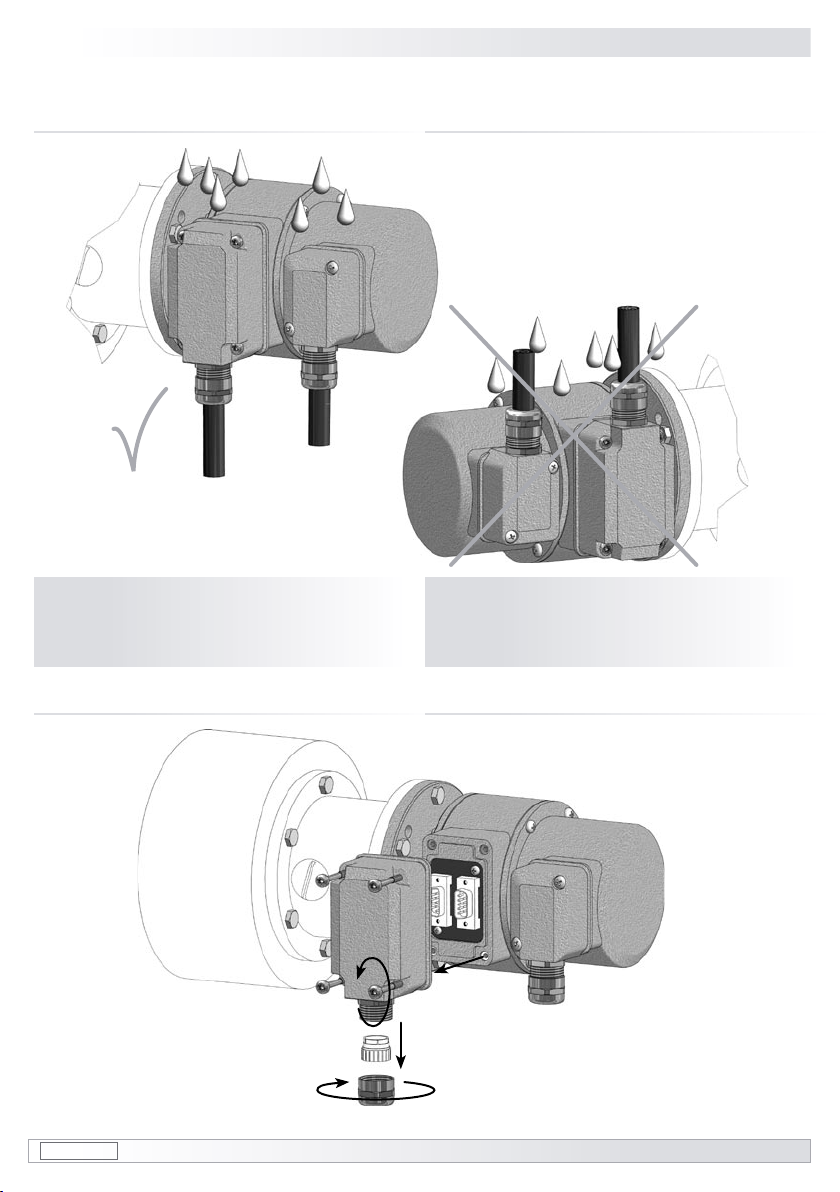
4.7 Schritt 5 - Klemmenkasten POG 90 4.7 Step 5 - Terminal box POG 90
4.6 Anbauhinweis 4.6 Mounting instruction
Wir empfehlen, die Kombination so
zu montieren, dass der Kabelan-
schluss keinem direkten Wasserein-
tritt ausgesetzt ist.
We recommend to mount the combi-
nation in such a manner that the cable
connection is not directly exposed to
water.
i
i

4Montage / Mounting
11 pog90-fsl_mb (08A1) MB154.1
4.9 Schritt 7 - Klemmenkasten POG 90 4.9 Step 7 - Terminal box POG 90
∼50 mm
4.8 Schritt 6 - Klemmenkasten POG 90 4.8 Step 6 - Terminal box POG 90

MB154.1 pog90-fsl_mb (08A1) 12
Montage / Mounting 4
4.10 Schritt 8 - Klemmenkasten POG 90 4.10 Step 8 - Terminal box POG 90
Kabelschirm
Cable shield Ansicht Y
siehe Abschnitt 6.1
Viewiew Y
see section 6.1
4.11 Schritt 9 - Klemmenkasten POG 90 4.11 Step 9 - Terminal box POG 90

4Montage / Mounting
13 pog90-fsl_mb (08A1) MB154.1
4.12 Schritt 10 - Klemmenkasten POG 90 4.12 Step 10 - Terminal box POG 90
Um 180° wendbarer Klemmenkasten
Reversible terminal box cover
4.13 Schritt 11 - Klemmenkasten FSL 4.13 Step 11 - Terminal box FSL

MB154.1 pog90-fsl_mb (08A1) 14
Ansicht Z
siehe Abschnitt 6.4
Viewiew Z
see section 6.4
5Maßzeichnung 5Dimension drawing
All dimensions in millimeters (unless otherwise stated)
Montage - Maßzeichnung / Mounting - Dimension drawing 4-5
Drehrichtung positiv
Positive direction of rotation
4.14 Schritt 12 - Klemmenkasten FSL 4.14 Step 12 - Terminal box FSL
Um 180° wendbarer
Klemmenkasten
Reversible
terminal box cover

15 pog90-fsl_mb (08A1) MB154.1
6Elektrischer Anschluss
6.1 Klemmenbelegung POG 90
6.1.1 POG 90 DN …
6Electrical connection
6.1 Terminal assignment POG 90
6.1.1 POG 90 DN …
Zwischen und besteht keine Verbindung.
There is no connection between and .
max. 1,5 mm2
max. AWG 16
Betriebsspannung nicht auf Ausgänge
legen! Zerstörungsgefahr!
Spannungsabfälle in langen Leitungen
berücksichtigen (Ein- und Ausgänge).
Do not connect supply voltage to out-
puts! Danger of damage!
Please, beware of possible voltage drop
in long cable leads (inputs and outputs).
6.1.2 POG 90 DN … I, DN … TTL, DN … R 6.1.2 POG 90 DN … I, DN … TTL, DN … R
Zwischen und besteht keine Verbindung.
There is no connection between and .
max. 1,5 mm2
max. AWG 16
6Elektrischer Anschluss / Electrical connection
Ansicht Y
Anschlussklemmen POG 90
siehe Abschnitt 4.10
View Y
Connecting terminal POG 90
see section 4.10
Ansicht Y
Anschlussklemmen POG 90
siehe Abschnitt 4.10
View Y
Connecting terminal POG 90
see section 4.10
MB154.1 pog90-fsl_mb (08A1) 16
Elektrischer Anschluss / Electrical connection 6
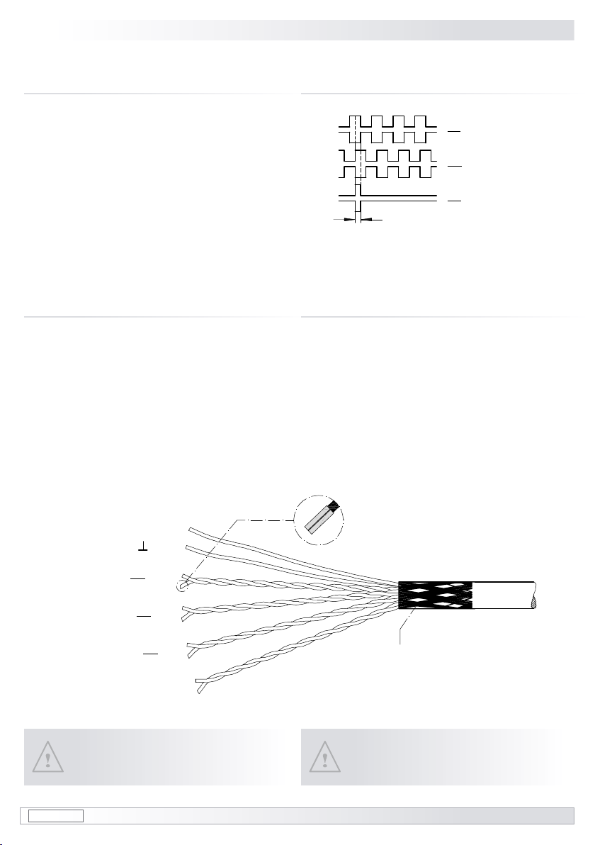
6.2 Ausgangssignale POG 90 6.2 Output signals POG 90
1nur bei Ausführung mit invertierten Signalen
only for versions with inverted signals
Signalfolge bei positiver Drehrichtung.
(siehe Abschnitt 5)
Sequence for positive direction of rotation.
(see section 5)
K1
K1 1
K2
K2 1
K0
K01
90°
6.3 Kabel HEK 8 (Zubehör)
Es wird empfohlen, das Baumer Hübner
Kabel HEK 8 zu verwenden oder ersatz-
weise ein geschirmtes, paarig verseiltes
Kabel. Das Kabel sollte in einem Stück und
getrennt von Motorkabeln verlegt werden.
Kabelabschluss:
Ausführung D ..., D ... I, DN … und DN … I:
1 ... 3 kΩ
Ausführung DN ... TTL und DN ... R:
120 Ω
6.3 Cable HEK 8 (accessory)
Baumer Hübner cable HEK 8 is recom-
mended. As a substitute a shielded twisted
pair cable can be used. It should have an
uninterrupted run, with ample clearance to
the drive power cable.
Cable terminating resistance:
Version D ..., D ... I, DN …and DN …I:
1 ... 3 kΩ
Version DN ... TTL and DN ... R:
120 Ω
Zur Gewährleistung der angegebenen
Schutzart sind nur geeignete Kabel-
durchmesser zu verwenden.
To ensure the specied protection
class of the device the correct cable
diameter must be used.
Aderendhülsen benutzen.
Use core-end ferrules.
rot/red = +UB
weiß/white = K1 (A+)
braun/brown = K1 (A-)
grün/green = K2 (B+)
grau/grey = K0 (R+)
rosa/pink = K0 (R-)
gelb/yellow = K2 (B-)
Kabelschirm
cable shield
blau/blue = GND
schwarz/black = n.c.
violett/violet = n.c.
17 pog90-fsl_mb (08A1) MB154.1
7Demontage
7.1 Schritt 1
7Dismounting
7.1 Step 1
6-7 Elektrischer Anschluss - Demontage / Electrical connection - Dismounting
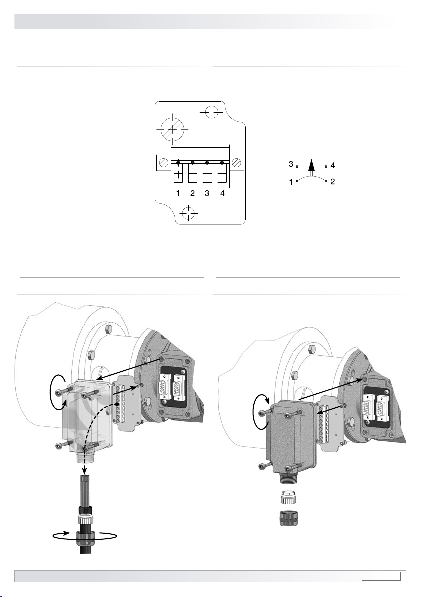
6.4 Klemmenbelegung FSL 6.4 Terminal assignment FSL
Schaltleistung
Switching capacity
6 A / ~ 200 V
Schließer
Make contact
Öffner
Break contact
Ansicht Z
Anschlussklemmen FSL
siehe Abschnitt 4.13
View Z
Connecting terminal FSL
see section 4.13
Other manuals for POG 90
1
This manual suits for next models
1
Table of contents
Languages:
Other Baumer Hübner Industrial Equipment manuals


