2/2
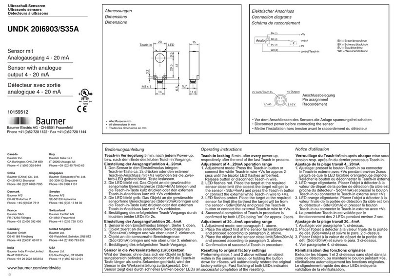
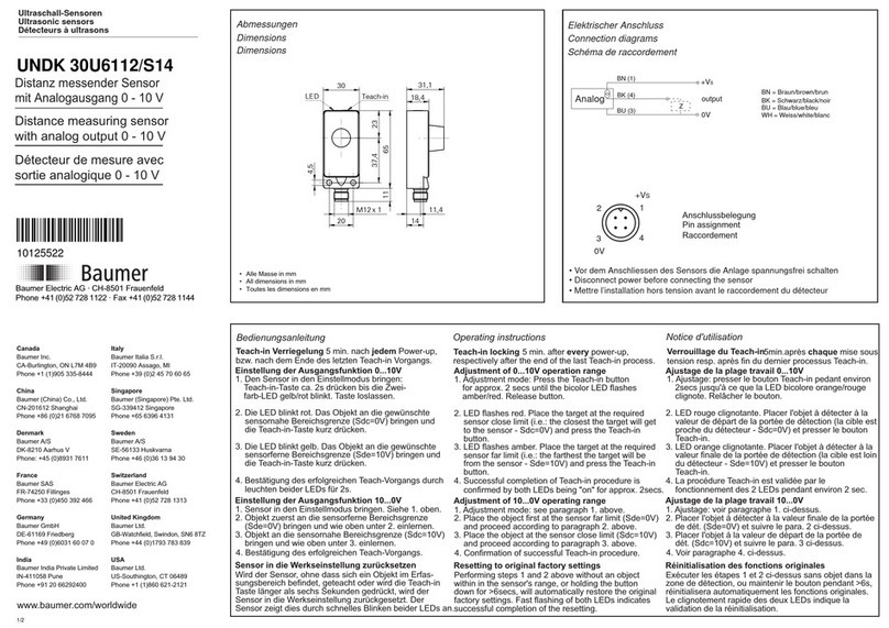
Teach-in Abläufe
Teach-in procedures
Procédures de Teach-in
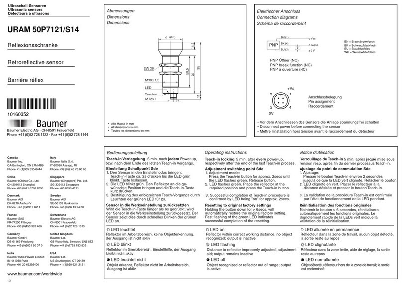
Anzeigeelemente / Bedienungselemente
- LED grün: Empfangsanzeige
- LED grün blinkend: Einstellhilfe / Verschmutzungsanzeige
- LED gelb: Ausgangsanzeige
- Taste: Teach-in
Statischer Teach-in Ablauf, für ruhende Objekte
1. Den Sensor in den statischen Teach-in-Modus bringen:
Taste ca. 2 sek drücken bis die LED (grün) blinkt
2.Das Objekt in die gewünschte ON-Position bringen und
Taste kurz drücken
3.Das Objekt in die gewünschte OFF-Position bringen und
Taste kurz drücken
DynamischerTeach-in Ablauf, für bewegte und kleine Objekte
1. Den Sensor in den dynamischen Teach-in-Modus bringen:
Taste ca. 5 sek drücken bis das Blinken der LED (grün)
von langsam nach schnell wechselt
Nach Loslassen der Taste beginnt der Sensor sofort mit dem
Einlernen der Minimal- und Maximalwerte
2.Teach-in beenden: Taste kurz drücken
3.Ausgangsfunktion von Hellschaltung (Standard) auf
Dunkelschaltung wechseln: Taste innerhalb 5 sek nach
"Teach-in beenden" kurz drücken
Teach Feedback nach demTeach-in Ablauf
Teach-in OK; LED (grün) leuchtet für 2 sek:
- Die eingelernte Anwendung arbeitet einwandfrei mit
genügend Unterschied der Lernpunkte und
innerhalb vom Erfassungsbereich des Sensors
Teach-in Warnung; LED (grün) blinkt für 2 sek:
- Die Differenz zwischen den Lernpositionen ist zu klein für eine
sichere Anwendung oder
- Der Sensor wurde ausserhalb seiner Bereichsgrenze eingelernt
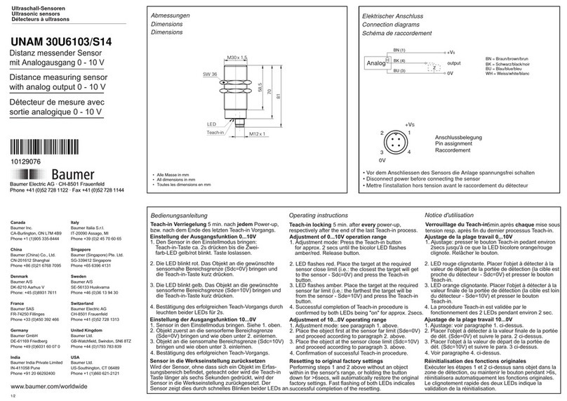
Display elements / Operating elements
- Green LED: excess gain indicator
- Green LED flashing: alignment aid / soiled lens indicator
- Yellow LED: output indicator
- Button: Teach-in
Static Teach-in procedure, for non moving parts
1. Set the sensor into static Teach-in mode:
press the button approx. 2 sec until LED (green) is flashing
2.Set the object to the desired ON-position and
press the button shortly
3.Set the object to the desired OFF-position and
press the button shortly
Dynamic Teach-in procedure, for moving and small objects
1. Set the sensor into dynamic Teach-in mode:
press the button approx. 5 sec until LED (green) flashing
changes from slow to fast
After releasing the button, the sensor starts immediately to
sense the max. and min. values
2.Stop the Teach-in procedure: press the button shortly
3.To change the output function from light operate (standard)
to dark operate: press the button within 5 sec after "stop the
Teach-in procedure" shortly
Teach feedback after Teach-in procedure
Teach-in OK; LED (green) is on for 2 sec:
- The teached application is OK, within its sensing range and
there is enough difference between the teached values
Teach-in warning; LED (green) is flashing for 2 sec:
- The difference between the 1st and 2nd teach position is too
small for a safe application or
- The sensor is teached beyond its sensing range
Eléments d'affichage / Éléments opérationnels
- LED verte: témoin de réception
- LED verte clignotante: aide de réglage / contrôle d'encrassement
- LED jaune: témoin de sortie
- Touche: Teach-in
Teach-in statique, pour objets fixes
1. Appuyez env. 2 sec sur la touche Teach-in jusqu'à ce que la LED
(verte) clignote
2.Mise en place de l'objet dans la ON-position
appuyer sur la touche Teach-in
3.Mise en place de l'objet dans la OFF-position
appuyer sur la touche Teach-in
Teach-in dynamique, pour de petits objets ou objets en mouvement
1. Appuyez env. 5 sec sur la touche Teach-in jusqu'à ce que la LED
(verte) clignote plus rapidement
Dès que vous relachez la touche Teach-in, le capteur commence
à enregistrer les valeurs min. et max. du signal
2.Terminer le cycle Teach-in: appuyez sur la touche Teach-in
3.La fonction standard mémorisée est la commutation claire
Pour une commutation sombre, appuyez sur la touche Teach-in
encore une fois dans les suivant 5 sec
Teach feedback après leTeach-in
Teach-in OK; LED (verte) s'allume pendant 2 sec:
- L'application travaille correctement, avec suffisamment de
différence de signal pour la reconnaissance des 2 points et
dans la portée du capteur
Alerte Teach-in; LED (verte) clignote pendant 2 sec:
- La différence entre le premier et le second point mémorisés est
trop petite pour une application sûre ou
- Le capteur a été utilisé hors des limites spécifiées
4.Bei Tauschen der Punkte 2 und 3, wird der Sensor auf Dunkel-
schaltung umgestellt, andernfalls hellschaltend
4.The sensor is set to dark operate by interchanging the order
of items 2 and 3, otherwise it is set to light operate.
4.En inversant l’ordre 2 et 3, le détecteur est commuté sur com-
mutation sombre sinon il reste en commutation claire
FAQ 1. How to teach using the external wire input?
Same teach procedure as with the button. Instead of pressing
the button connectTeach-in input to +Vs (PNP) or 0V (NPN).
Teach feedback: Output open =Teach-in OK
Output closed =Teach-in warning
2. How to teach on maximum sensitivity / sensing range?
Cover the receiver lens. Go into the dynamicTeach-in mode.
After stopping theTeach-in procedure, press the button once
more to switch the output to dark operate, if desired.
3. What happens when ON- and OFF-Position are the same?
Even if there is no difference between the two signals, the
switching point is set on this position as good as possible.
4. Why is the green LED flashing?
-The sensor is operated at too little signal reserve.
-The sensor is inside aTeach-in procedure.
-Teach feedback: too little signal difference for a safe application
(2 sec fast flashing).
- Option to switch to dark operate (5 sec double flashing).
1. Comment fonctionne leTeach-in externe?
Exactement comme pour la toucheTeach-in, en raccordant l'entrée
Teach-in externe avec +Vs pour PNP (0V pour NPN).
Teach feedback:
2. Comment adjuster à la sensibilité maximale / plage de détection?
Couvrir la lentille du récepteur de façon à prévenir la réception de
signal. Démarrer unTeach-in dynamique. Après avoir terminé le
Teach-in, il est possible de changer la sortie en commutation sombre.
3. Qu'est-ce qui ce passe si ON- et OFF-position sont les mêmes?
Même si la différence entre les deux positions est zéro, le capteur
choisi le point de commutation le plus proche possible.
4. Pourquoi est-ce que la LED verte clignote?
- Le capteur travaille avec insuffisament de réserve de signal.
- Le capteur se trouve dans une procédure deTeach-in.
-Teach-in avec insuffisament de différence (2 sec, rapide).
- Possibilité de changer en commutation sombre (5 sec, double).
Sortie non commutée =Teach-in OK
Sortie commutée = alerteTeach-in
1. Wie funktioniert der externeTeach-in-Vorgang?
Er ist identisch zurTaste, indem man denTeacheingang auf +Vs
bei PNP, ( 0V bei NPN ) verbindet.
Teach Feedback: Ausgang offen =Teach-in OK
Ausgang geschalten =Teach-in Warnung
2. Wie teacht man auf max. Empfindlichkeit / Tastweite?
Den Empfänger so abdecken dass er kein Licht mehr empfängt.
Dann in den dynamischenTeach-in-Modus gehen. Nach beenden
desTeach-in, kann noch auf Dunkelschaltung gewechselt werden.
3. Was passiert wenn die ON- und OFF-Position gleich sind?
Obwohl die Differenz zwischen den Lernpunkten Null ist, wird
der Schaltpunkt möglichst genau auf diese Position eingestellt.
4. Wieso blinkt die grüne LED?
- Der Sensor arbeitet mit ungenügender Signalreserve.
- Man befindet sich imTeach-in-Modus.
-Teach-in mit zu wenig Differenz zwischen den Lernpositionen
(2 sek schnelles Blinken).
- Möglichkeit auf dunkelschaltend zu stellen (5 sek, doppel).
Hinweis: Für Montage und Inbetriebnahme sind geeignete ESD-
Schutzmassnahmen zu ergreifen. Empfehlung: als Minimal-ESD-
Schutzmassnahme ist der Metallrahmen anzufassen, an dem der
Sensor montiert ist, bevor der Sensor geteachet wird.
Note: proper ESD precautions should be taken for erection and
commissioning. Recommendation: as minimum ESD protection
measure, the metal frame is to touch, to which the sensor is
mounted before the sensor is taught.
Remarque: mesures de protection ESD appropriées doivent être prises
pour le montage et la mise en service. Recommandation: minimum
comme mesure de protection ESD, la structure métallique est au
toucher, à laquelle le capteur est monté devant le capteur est enseigné.
