Baumuller DSM1 Guide

TAM00720 1
DSM1 10/2015
Three-phase-synchronous motor English
TAM00720_eng
DSM1
Three-phase-synchronous motor
Version: 10/2015
English
Commissioning
and Maintenance Instructions

TAM00720 2
DSM1 10/2015
Three-phase-synchronous motor English
LEGAL DOCUMENTATION NOTICES
Copyright
This documentation may be copied by the owner in any quantity desired for internal use, only.
For other purposes this documentation and extracts thereof may neither be copied nor duplicat-
ed. The use and notification of documentation contents are not permitted. Terms or business
signs mentioned in this documentation can be trademarks, whose use by third parties for their
own purposes can violate the rights of the owners.
Liabilities
This documentation is part of the device/machine. This commissioning- and maintenance guide
must be available to the operator at all times and must be in legible condition.
If the device/machine is sold or moved to another location this documentation must be passed
on together with the device/machine by the owner. After the sale of the device/machine this
original as well as all copies must be handed over to the purchaser. After disposal or another
end of use this original and all copies are to be disposed of.
The corresponding documentations of previous versions are invalidated by the handover of the
present documentation.
Please, note that specifications/data/information are current values according to the printing
date. These statements are not legally binding with regard to measurements, computations
and calculations.
Baumüller DirectMotion GmbH reserves the right in developing its products further and chang-
ing the technical data and the handling techniques of the Baumüller products.
No responsibility is assumed for the correctness of this documentation unless noted otherwise
in the terms and conditions of sale and delivery.
BAUMÜLLER DirectMotion GmbH
D-37581 Bad Gandersheim
www.baumueller.de

TAM00720 3
DSM1 10/2015
Three-phase-synchronous motor English
Table of Contents
1
General safety instructions................................................................................4
1.1
Safety.........................................................................................................................................4
1.2
Intended use ..............................................................................................................................5
1.3
Prohibition of unauthorized modifications and changes ............................................................6
2
Operating conditions..........................................................................................7
2.1
Product description ....................................................................................................................7
2.2
Scope of supply..........................................................................................................................7
2.3
Technical data............................................................................................................................8
2.4
Transport, temporary storage ..................................................................................................10
2.5
Installation conditions, cooling specifications ..........................................................................11
2.6
Balancing, output elements, vibrations....................................................................................12
3
Installation.........................................................................................................13
3.1
Safety instructions....................................................................................................................13
3.2
Positioning, fastening...............................................................................................................13
3.3
Electrical connection................................................................................................................14
4
Commissioning, operation...............................................................................16
4.1
Safety instructions....................................................................................................................16
4.2
Tests prior to commissioning...................................................................................................17
4.3
Commissioning, operation .......................................................................................................17
4.4
Failures ....................................................................................................................................18
5
Inspection and maintenance............................................................................19
5.1
Inspection.................................................................................................................................19
5.2
Maintenance.............................................................................................................................20
6
Disposal.............................................................................................................20
7
Pole assignments (power and signal connections).......................................21
7.1
Resolver – KTY within the power connection..........................................................................21
7.2
Resolver – KTY within the signal connection...........................................................................22
7.3
SRS/SRM50; SKS/SKM36 – KTY within the power connection..............................................24
7.4
SRS/SRM50; SKS/SKM36 – KTY within the signal connection: .............................................25

TAM00720 4
DSM1 10/2015
Three-phase-synchronous motor English
1 General safety instructions
1.1
Safety
This electric motor was built complying with the state of safety engineering and the operational safety
was checked prior to leaving the company.
Please, pay attention to the following in order to ensure a proper commissioning and its safe use:
• The present commissioning- and maintenance instructions and attached supplementary parts, if
required.
• The attached safety- and commissioning notes.
• The technical product documentation.
• The commissioning- and safety notes of the inverter’s manufacturer.
• The national, local and plant-specific regulations regarding the final product.
• The motor must be operated with appropriate inverters, only.
• All components related to the motor must comply with the application rules.
In dealing with this product the following dangers are pointed out:
Dangers due to
• lifting operations and transport processes
• electric current
• moving parts
• hot surfaces
• EMC interferences
• Mechanical overload
• thermal overload
Please, pay attention to all safety notes - especially those, which are marked by symbols, in order to
avoid danger to persons and material assets or to minimize existing residual risks.
Risk of fatal injury from electrical current
The symbol indicates that injuries, which result in death or serious injuries could occur, if not
avoided.
Warning of general dangers
The symbol indicates that severe personal injuries or property damage could result, if not
avoided.
Warning of dangerous situations
The symbol indicates that the installation or work environment could be damaged, if not
avoided.
Do not touch
The symbol indicates that severe injuries could result, if not avoided.
Unauthorized action
The symbol indicates that severe injuries could result, if not avoided.
Warning of hot surfaces
The symbol indicates that, if not avoided, could result in severe injuries.
Electrostatic sensitive devices
The symbol indicates that the installation or work environment could be damaged, if not
avoided.

TAM00720 5
DSM1 10/2015
Three-phase-synchronous motor English
1.2 Intended use
The use of an electric motor is permitted within its intended use, only. In this connection the electric
motor must exclusively be used by considering all specified cases of application within the technical
data of this commissioning- and maintenance guide.
All works referring to mounting, commissioning, maintenance as well as during operation must be car-
ried out by qualified personnel, only.
Within the scope of the mentioned safety instructions, the term „qualified personnel“ is to be under-
stood a person, who was skilled and authorized to a special subject area. This person is authorized to
install, mount, commission and operate devices, systems and current cirucuits by complying with the
valid safety standards (EN 50110-1).
Improper handling can cause severe personal injuries and property damages.
This electric motor is intended for the use within industrial systems and is subject to the following
standards and guidelines:
Standards
EN 60034-1, EN 60034-5, EN 60034-6, EN 60034-7, EN 60034-9, EN 60034-11, EN 60034-14 EN
60204-1
EU Low-Voltage Directive (LVD)
Electric motors of this series meet the requirements of the low-voltage directive (conformity).
EU Machinery Directive
Electric motors are components, which are to be built into machines complying with the Machinery
Directive. The conformity of the final product with this directive must be approved prior to being
commissioned (consider EN 60204-1 “Electrical equipment of machines”).
EU EMC Directive
The operation of the electric motor must meet the protection requirements of the EMC Directive
2004/108/EG. The proper installation (e.g. physical separation of signal lines and power cables,
shielded lines and cables and so on) is within the responsibility of the installation contractor and the
system provider. During the operation with the power inverter, the EMC notes of the manufacturer
of the power inverter, the encoder and the brakes must be considered, also.
Furthermore, consider the binding national, local and system-specific specifications!
The electric motor is designed for the following environmental conditions:
• Environmental temperature: 0 °C bis +40 °C
• Installation altitude: ≤1000 m above sea level
• Relative air humidity: 5 % to 85%
Pay attention to differing data on the rating plate as well as to the data of the technical documents.
The conditions at the operating site must comply with all information on the rating plate.
The use within hazardous areas is prohibited provided that it was designed for this
purpose (consider additional information). Furthermore, neither flammable gas mixtures
nor dangerous dust concentrations may exist within the environment of the electric mo-
tor Motor parts under tension and parts, which are hot could catch fire and cause severe
injuries and property damages.
If higher requirements are demanded in special cases as e.g. in use within non-
industrial systems, these requirements must be ensured during installation (e.g. touch
protection against children’s fingers).
Motor version with rare-earth magnets:
TAM00720 6
DSM1 10/2015
Three-phase-synchronous motor English
The following dangers can occur near a drawn or open rotor with a strong magnetic
field:
•Persons with electronic or metallic implants (e.g. pacemakers, hearing aids, plates
or nails) are endangered, if the distance between implant and magnetic pole is less
than 0.5 m.
•Due to strong magnetic forces pulling on ferromagnetical parts the following can
occur:
oRisk of injury by crushing
oDanger of destruction of measuring and mounting tools, cheque cards, watches
and so on.
oPollution of the rotor core by metal chips or metal powder pulled on by magnetic
forces
Thermal danger:
Caution: Danger of burning!
Surface temperatures of over 70°C can occur at the motors. Safety device measures
must be provided when required!
Temperature-sensitive parts must not be attached or be in contact with hot surfaces, as
e.g. normal cables or electronic parts.
A thermal motor overload can cause the destruction of the winding, the bearing and can
demagnetize the rare-earth magnets. Use the temperature sensor to control the
temperature.
1.3 Prohibition of unauthorized modification or alteration at the electric motor
Any unauthorized modifications and alterations at the electric motor are prohibited due
to safety reasons. Contact the motor manufacturer in case of need.
Generally, never dismount or decommission safety devices to operate the electric mo-
tor.

TAM00720 7
DSM1 10/2015
Three-phase-synchronous motor English
2 Operating conditions
2.1 Product description
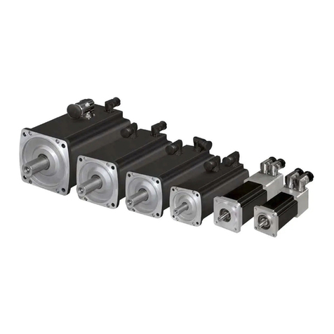
The electric motors of the series DSM1xx are 3-phase synchronous motors with rare-earth magnets.
2.2 Scope of supply
The supply is put together order-related.
•If damages incurred during transit are determined at delivery, the transport company immediate-
ly must be informed about this.
•Immediately upon receipt you must compare the performance data and the motor type with your
ordering data. If visible deficiencies or incomplete delivery are determined the responsible
Baumüller subsidiary or the main Baumüller company in Nuremberg must be informed.
In both cases motor commissioning is prohibited until the deficiency was professionally corrected.

TAM00720 8
DSM1 10/2015
Three-phase-synchronous motor English
Rating plate
The rating plate is the identifier for each electric motor. The motor number, in particular, is uniquely de-
fined and is essential to ensure an in-house traceability. The rating plate must be readable at all times.
Never remove the rating plate from the motor.
The rating plate can be customer-specific, also!
Standard rating plate data:
Bild 1: Leistungsschild
2.3 Technical data
Type of drive Permanent-magnet-excited 3-phase synchronous motor
Type of construction (EN 60034-7) IM B5
Mounting position horizontal
IM V1
Mounting position vertical, shaft end to the
bottom
IM V3
Mounting position vertical, shaft end to the top
Please note: At mounting position IM V3 in connection with protection class IP44 the shaft sealing
must be protected against entry of water and dirt.
Protection class (EN 60034-5) considering the shaft sealing
IP 44 Standard: without shaft sealing ring
IP 65 Optional: with shaft sealing ring,
without considering the shaft sealing
IP 65 Standard: without shaft sealing ring
1
Manufacturer
2
Standards and approvals
3
Motor number
4
Temperature sensor
5
Feedback / rotary encoder
6
(optional) brake – supply voltage
7
(optional) brake - power
8
(optional) brake – holding torque
9
Item number ID
10
Motor is operated with inverter
11
Rated frequency f
N
12
Temperature class
13
Permissible environmental temperature
14
Operating mode
1
5
Type of protection
16
Motor type / name
17
Standstill current I
O
18
Standstill torque M
O
19
Rated speed n
N
20
Rated power P
N
21
Rated voltage U
N
22
Motor type: 3-phase motor
1
4
5
3
9
8
7
6
2
22
21
16
17
18
19
20
10
11
12
13
14
15

TAM00720 9
DSM1 10/2015
Three-phase-synchronous motor English
Attention: The mentioned protection classes only are reached if the connectors were mounted com-
pletely (the main and the control connections).
Cooling process (EN 60034-6) IC 410 Standard: Self-surface cooling; cooling without
using a fan, but by natural ventilation
Electrical connections (see chapter 7).
Receptacle orientation Standard: Radial outgoing
Optional: Others on request
Main connection Receptacle 8-pole
Standard: U, V, W +temperature sensor
Optional: Brake
Control connection 12-pole Standard: Resolver
Optional: Others on request
Thermal motor protechtion (EN60034-11) Temperature sensor KTY84/130 in the stator winding
Barrier (EN 60034-1) Temperature class F (∆θ = 105 K)
Ambient temperature 0°C... + 40°C
Installation altitude (EN 60034-1) ≤1.000 m above sea level (standard)
Bearing Deep-groove ball bearing with permanent lubrication
Calculated service life of bearing L
H10
20.000 h (approximate value)
Service life of shaft seal see chapter 5.2 Maintenance
Vibration quantity step (EN 60034-14) Standard: A
Nonstandard: B
Shakeproof (EN 60068-2-6) radial: 3 g (10 Hz to 100 Hz)
axial: 1 g (10 Hz to 100 Hz), with brake 0,5 g
Concentricity shaft end (DIN 42955) Standard: N
Nonstandard: R (reduced)
Holding brake Optional
Actual speed value encoder Nonstandard: 2-pole resolver
(high-grade version on request)
Optional: Absolute encoder with hiperface interface
Optional: Absolute encoder with Endat interface
Attention!
If the delivered electric motor doesn’t correspond to the standard version accordant to the technical list
or if special contractual terms were agreed upon, technical deviations referring to this commissioning
and maintenance guide can occur. Please, ask for the corresponding technical additions.

TAM00720 10
DSM1 10/2015
Three-phase-synchronous motor English
2.4 Transport, temporary storage
Transport:
For the permissible environmental conditions, which may have an effect on the motor
during transport, please refer to DIN EN 60721-3-2 (class 2K2/2M1). The permissible
temperature range was contrary to the DIN reduced to – 15 °C to + 60 °C.
Suitable load carrying devices must be used, as e.g. belt straps, single slings and so on.
If lifting lugs are provided at the motor, these also can be used for lifting.
Do not use the motor receptacles as transport safety devices or lifting lugs.
The particular country-specific rules must be observed during transport. Lifting devices
as well as transport and load handling devices must meet the requirements.
Please, refer to the technical data concerning the declaration of weight of the individual electric mo-
tors.
The motor shaft and the connection surfaces must be protected against corrosion. The motor must be
transported with a protective cover for the shaft, only. Damages at the motor shaft must be avoided.
Temporary storage:
In case a motor isn’t placed in service within a narrow time frame, it must be stored in dry, low-dust as
well as vibration-resistant indoor spaces (V
eff
≤0,2mm/s).
The electric motors should not be stored longer than 2 years within a constant temperature range,
which is between -15 and +60 °C. Higher storing temperatures within the scope of the operating tem-
perature accelerate the aging process of the sealings and the bearing greases and therefore affect the
service life prior to commissioning. It is absolutely necessary to avoid solar radiation, ultraviolet light
and ozone, because these also have a share in the aging of the sealing elements!
Please, consider that the warranty periods are assured from the date of delivery. Therefore, we rec-
ommend to limit storage time to a minimum.
However, if a longer storage cannot be avoided, then the environmental conditions (class 1K2/1M1)
mentioned in DIN EN 60721-3-1 must be observed. Contrary to the DIN the temperature range may
be exceeded from – 15 °C to + 60 °C.

TAM00720 11
DSM1 10/2015
Three-phase-synchronous motor English
2.5 Installation conditions, cooling specifications
Environment:
The motor can be installed indoor within dusty and humid environments correspondent to its protection
class (see rating plate).
As long as special agreements weren’t agreed upon, the drive is designed to the following standard-
ized climatical application conditions:
•Environmental temperature 0 °C to 40 °C
•Installation altitude ≤1000 m above sea level
Relative humidity is 5% to 85%. For the other permissible application conditions refer to
DIN EN 60721-3-3 (class 3K3/3Z12).
These climatical conditions must be unconditionally observed at installation.
Generally, it is necessary to keep aggressive, corrosive, abrasive as well as plastic-dissolvent media
from the motor and its cooling air.
Contact the motor manufacturer if an outdoor installation must be carried out.
Cooling specifications:
Environmental conditions see chapter 2.4 and technical product data.
Cooling process IC 410 – Natural cooling without fan.
Basically, the following must be observed:
•The heat convection and the thermal radiation must not be affected by the installation conditions.
•In the case of forced air cooling, the cooling air must be able to freely enter and the hot air must
freely exit. Do not draw in the heated exit air anymore.
•The distance to adjacent machine parts should not fall below 100 mm.
•The housing surface and the air in-/outlets must be cleaned regularly, if dirt accumulation is ex-
tremely.
Mounting specifications:
By coupling the motor to the installation surface a part of the motor dissipation is diverted via the
flange.
The following chart 1 demonstrates the measurings of the installation surfaces dependent of the shaft
height. These specifications are lower limiting values regarding safe heat dissipation via the flange
surfaces of the motor.
Shaft height Steel plate, width x height x thickness in
mm Installation surface in
m
2
DSM115 250 x 250 x 10 0,0625
DSM117 250 x 250 x 10 0,0625
DSM130 250 x 250 x 10 0,0625
DSM150 350 x 350 x 10 0,12
DSM170 500 x 500 x 10 0,25
DSM190 500 x 500 x 10 0,25
Chart 1: Installation surface
The heat dissipation conditions improve where the installation surfaces are larger.
An isolated installation of the motors is not permitted!

TAM00720 12
DSM1 10/2015
Three-phase-synchronous motor English
2.6 Balancing, output elements, vibrations
Don’t strain the shaft and the bearing with strokes!
During mounting or demounting of output elements the motor must not be affected by
axial forces.
The generally required measures regarding the protection against contact of the output
elements must be considered.
The featherkey must be secured against being expelled, if a motor is placed in service
without the output element.
Balancing
At the optional version having a feathrkey the rotors are dynamically balanced by half the feather-
key (according to EN 60034-14 / ISO 8821 / ISO 1940).
Output elements:
An accordant balancing type must be considered at mounting the output element. The output ele-
ments must be balanced in accordance with ISO 1940.
In the case of output elements having to be mounted or removed (e.g. clutch disk, gear wheel, belt
pulley), appropriate equipment must be used.
• Use tapped hole within the shaft end.
• At removal use spacing washers for the mechanical protection of the shaft.
Warm up the output elements before mounting them, if required (max. permissible temperature at
the shaft end may be 150 °C for a short period). Attention!
• At the shaft version without featherkey the drive elements must be fixed on the output shaft by
using appropriate clamping sets.
• At shaft versions with featherkey the output elements must fit closely to the shaft shoulder.
Please note: The bevel and accordingly the radius at the output element and the shaft radius to
the shoulder must have been phased.
• If the tapped hole in the shaft end is used for the axial fastening of output elements (e.g. belt
pulleys), the tightening torques shown in the following chart 2 must not be exceeded:
Thread Tightening
torque
in Nm
M5 2,2
M8 10
M10 20
Chart 2: Tightening torques demonstrated with a locking bolt S of a belt pulley
Appropriate measures must be made regarding screw locking!
S

TAM00720 13
DSM1 10/2015
Three-phase-synchronous motor English
Vibrations:
The system vibration behavior at the application site can lead to an increase of the vi-
bration values at the motor due to the output elements, the installation conditions, the
alignment and the positioning as well as the influence of external vibrations.
The permissible vibration values in accordance with EN 60034-14 must not be exceed-
ed to achieve a correct functioning of the motor and a long bearing service life. In cer-
tain circumstances it can be possible that the complete balancing of the rotor together
with the output element is required (in accordance with ISO 1940).
The simulated vibrations after mounting must not exceed the permissible accelerations
(see chapter 2.4 Technical data).
If changes compared to the normal operation occur, in case of doubt the motor must be
switched off, the cause must be located and perhaps the manufacturer must be con-
tacted.
3 Installation
3.1 Safety instructions
Previous to the installation:
Never mount or put into operation a damaged electric motor.
Never mount the electric motor into a damaged machine.
Prior to mounting make sure that the electric motor is suitable for your machine.
During installation:
Mount the motor to the provided mounting options, only.
Avoid hammer strokes or prohibited shock loads during the mounting.
Attach all covers and safety appliances. All safety appliances must meet the applicable
regulations (e.g. EN 60204).
3.2
Positioning, fastening
Prior to mounting as well as during mounting, check if
• the motor is free of damage (e.g. the shaft sealing must in no way whatsoever be damaged by
sharp or pointed objects).
• the motor isn’t mounted in the danger zone of other facilities.
• the intented use is complied with. (see chapter 1.2, chapter 2.4)
Rating plate specifications, observe warning and instruction plate specifications.
• the anticorrosive at the shaft end was removed residue-free.
Do not wet the shaft sealing, if commercial solvents, as e.g. acetone or petroleum ether are used!
• the motor is in accordance with the local environmental conditions and the environmental influ-
ences (see chapter 2.4).
• the machine’s installation space is suitable for the cooling type of the electric motor (see chapter
2.6)
The motor installation must allow the sufficient dissipation of heat via the housing surface and via
the motor flange surface (see chapter 2.6).

TAM00720 14
DSM1 10/2015
Three-phase-synchronous motor English
• the motor is able to be mounted and operated with the available fastening options and the connec-
tion data.
The installation dimensions of the motor together with the tolerance indications are to be found in
the technical data of the product. A correct and even surface mounting of the motor must be con-
sidered. The guide seats and contact surfaces must be undamaged and clean. They should be in
accurate connexional position to the shafts, to avoid damaging loads due to displacement for bear-
ings, shafts and housings within the entire system. During the tightening of the flange fastening
screws (strength class 8.8 at least) distortions at the flange connection must be avoided.
• at vertical installation with the shaft end to the top, no liquid can infiltrate the upper bearing.
• the permissible radial forces must not exceed the corresponding operating characteristics of the
technical data referring to the product (if need for clearance contact Baumüller subsidiary).
With regard to axial forces clearance is required via the motor manufacturer.
• the brake (optional) is able to be released after applying the operating voltage (there is an audible
switching sound).
• the rotor is turning smoothly and without dragging noises.
At a motor with an integrated brake the brake at first must be released.
• the version of the motor and encoder connections comply with the specifications of the technical
data of the product.
• the output elements or the drive elements are protected.
• the complete cooling system is functioning.
• the motor surface must be free from soilings.
• Versions, which possess approvals for special application fields (e.g. E1) were mounted in accord-
ance with approval regulations.
3.3 Electrical connection
Important notes:
The work must be performed by qualified personnel, exclusively!
The work must be performed within an installation, which is disconnected and secured
against re-connection (also auxiliary current circuits).
The work must be performed at motor standstill, only!
At 3-phase synchronous motors with permanent-magnet excitation it can happen that
voltages of > 60 V occur at rotating rotors at the motor contacts.
Comply with the regulations while working within electrical installations!
Attention! The safety instructions for working in electrically installations according to EN 50110-1
must be complied with:
• Activate
• Protect against re-connection
• Verify that the installation is dead
• Carry out earthing and circuiting
• Provide protection against adjacent live parts or provide with barriers
The electric motor must be operated together with a corresponding configured invert-
er. The direct connection to the 3-phase system can lead to the destruction of the
motor.
Consider the correct phase sequence and the terminal assignment!
The electrical connection, the protective conductor connections and the shielding
connections (using shielded cables) must durably be made safe!
Never touch the contacts of encoders and temperature sensors with your hands or
with tools, which are electrostatically charged or could be electrostatically charged!
Encoders and temperature sensors are electrostatically sensitive devices.
Electrical installation:

TAM00720 15
DSM1 10/2015
Three-phase-synchronous motor English
• The system installer carries the responsibility concerning a proper installation.
• The motor data on the rating plate must be considered.
• Connection cables and connectors regarding the occuring voltages and current ranges must be
rated correctly and must apply to the installation type.
• The motor connection including its components (brake, encoder, and so on) must be carried out in
accordance with the circuit diagrams (see attached circuit diagrams or chapter 7).
• To avoid electromagnetical EMC troubles of the motor supply cables and their consequences on
the encoder and the control systems shielded power- and encoder cables must be used. For this
purpose consider the EMC instruction of the manufacturer of the inverter.
• For reasons of operational safety we recommend to use the assembled connection cables of Bau-
müller (see technical product list).
• Prior to installation the connector receptacles and connectors must be checked for damages, cor-
rosion, pollution and moisture.
• To guarantee the protection class the correct and solid fit of the plug screw fittings, the sealings
and the sealing surfaces of the plugs must be regarded.
• Note! In order to guarantee the protection class the turnable sockets shouldn’t be changed in their
connection direction by turning them more than 5 times, as well.
• Plug connections must not be exposed to any mechanical loads. If required, add anti-rotation,
strain, thrust as well as flex reliefs.

TAM00720 16
DSM1 10/2015
Three-phase-synchronous motor English
4 Commissioning, operation
4.1
Safety instructions
Operations at the electric motor:
Operations at the electric motor must be executed only, if the motor is at standstill,
under off-circuit conditions and cooled down. All screws a.s.o., which were untight-
ened at the motor must be tightened prior to commissioning, again.
The technical instructions in the accordant chapters of this commissioning and
maintenance guide must be complied with during all operations.
Attention!:
During operations at the motor an optional holding brake must not take up a securing
position (e.g. the holding of loads)!
Risk of death by electrical current:
Assure, that the electric motor is activated and under off-circuit conditions.
Under no circumstances the motor connections may be loosened during operation.
Connect the measurement devices in currentless and de-energized state, only.
Start operations at the motor connections not until assuring that neither potential nor
voltage are present.
There is electric potential at the motor contacts and the motor windings. Never touch
these components/elements during operation.
Installation and demounting of safety devices:
Do not operate the electric motor without installing the safety devices.
The motor must be put out of operation to mount and demount components and sys-
tems, which are provided to monitor the safe motor operation.
Danger! Do not touch!
Prior to touching the electric motor, assure that the electric motor is at standstill and is
protected against unintentional restart.
The motor must be at standstill and within a non-energized state before you can touch
the output shaft. Otherwise, the rotating rotor causes a hazard.
Danger of burning! Never touch the motor housing within rated load operation. Sur-
face temperatures of 70°C and above can occur at the motors.

TAM00720 17
DSM1 10/2015
Three-phase-synchronous motor English
4.2 Tests prior to commissioning
• The drive must be free of damage and must be located out of the hazard zone of other installa-
tions.
• The motor must be aligned and fixed correctly. Screw fittings must be tightened correctly.
• The associated safety devices (mechanical, thermal, electrical) must be mounted.
• The motor connection must be provided correctly.
• The cables don’t touch the motor surface.
• The protective conductor system must be provided correctly and must be tested for correct op-
eration.
• The drive doesn’t block (release brake, insofar as availabe).
• Emergency stop functions must be checked.
4.3 Commissioning, operation
Notes regarding the function of the brake (insofar as available):
The brake is a holding brake provided with emergency stop functions.
(Power failure, emergency stop) .
Do not use the holding brake as an operating brake.
Commissioning must be carried out by qualified personnel, only.
The commissioning instruction of the inverter must absolutely be observed.
Tests during commissioning:
• Release brake, if required.
• Were the motor components, as e.g. brake, encoder etc., tested for correct operation and are
the application conditions complied with?
• Were the electric connections and contacts provided and mounted according to instructions
(consider circuit diagrams, see chapter 7 or the attached circuit diagrams)?
• Were all safety measures met and are they fully functional, regarding the exclusion of contact
parts under tension, hot surfaces as well as rotating and moving parts and components?
• Were the output elements mounted and set in accordance with the manufacturer’s instructions?
• Was the maximum permissible speed n
max
of the motor ensured so that it cannot be exceeded?
The maximum permissible speed n
max
is the greatest temporary permitted operating speed.
Tests during operation:
• Pay attention to extraordinary noises.
• If streaking and scratching noises, dragging noises or the like occur, immediately put the drive
out of operation and detect the cause.
• Motor surface and connecting cables must be checked on dirt (e.g. dust deposits, oil contamina-
tion, moisture etc.).
• Maintenance intervals must be observed.

TAM00720 18
DSM1 10/2015
Three-phase-synchronous motor English
4.4 Failures
Safety instructions:
Troubleshooting and correction of failures must be executed by qualified personnel,
only.
Do not take safety devices out of operation – not in the test run either.
Remove and mount connecting cables off circuit and within a protected state, only.
Observe the 5 safety regulations of “Release” (see section 3.3).
Observe hot surfaces!
Always observe the following at failures:
• The operation manual of the machine/installation
• The operation manual of the inverter
• Contact the manufacturer of the motor or inverter, if required
The following parameters must be kept at hand:
• Rating plate data
• Type and degree of failure; attendant circumstances of the failure
• Application data (speed cycle, speed and power, which exceeded the time, environmental
conditions)
The following selection of failure causes can help to detect errors:
Failure Cause of error Correction
Motor doesn’t start-up Controller enable is missing
Controller error, encoder error
Brake doesn’t release
Brake is defect
Voltage supply is missing
Rotating field
Activate controller enable
Read out the error list at the
inverter or the controller, correct
the errors
Triggering, check connecting
and voltage supply
Manufacturer must repair
Check connecting and voltage
supply
Check phase sequence, ex-
change connecting cables, if
required
Irregular running
Shielding of the connecting
cables are insufficient
Controller parameters too high
Check shield connection and
grounding
Optimize controller parameters
Vibrations Coupling elements or work
machine is badly balanced
Nonconform alignment of
driveline
Fastening screws are loose
Re-balance
Realign the machine unit
Check and fasten the screwed
fastenings
Failure Cause of error Correction
Running noises Foreign particles in the motor Motor manufacturer must

TAM00720 19
DSM1 10/2015
Three-phase-synchronous motor English
Bearing damage repair
Motor manufacturer must
repair
Motor gets too warm
Motor temperature monitoring
responses
Overload of drive
The motor surface and the air
ducts are dirty
The mounting conditions are
restricted
The brake doesn’t release
properly – dragging brake
Check the motor load and
compare with the power rating
plate
Clean the motor surface or
the air ducts
Check motor installation by
appropriate sections 2.6 or
3.2
Motor manufacturer must
repair
Current input too high, motor
speed torque too low Notch position incorrect Check notch position and
adjust, if required
Chart 3: Failures
5 Inspection and maintenance
Operations at the electric motor:
Operations at the electric motor must be executed, if the motor is at standstill, off cir-
cuit and cooled down. All loosened connections during the works at the motor, as e.g.
screws etc., must be fastened after inspection or maintenance again.
Regard the technical instruction within the accordant chapters of this commissioning
and maintenance manual.
By all means while doing maintenance works observe the safety instructions, which
apply to the motor commissioning as well (see section 4.1).
Attention!
The optional holding brake may not take up securing functions during motor works
(e.g. holding of loads)!
5.1 Inspection
The motor must be cleaned regularly depending on the pollution degree, to assure permanent and
correct heat loss dissipation.
Wear limits must be specified if a brake was installed optionally (e.g. max. permissible operating air
gap, limited number of emergency braking). The current wear degree must be checked regularly. The
brake must be replaced if the permissible wear limits were reached (see section 5.2).
If a shaft sealing was installed optionally the correct functioning must be checked (leakage) regularly.

TAM00720 20
DSM1 10/2015
Three-phase-synchronous motor English
5.2 Maintenance
Dependent on the operating conditions (as e.g. operating type, temperature, speed and load) the
bearing and sealing elements can have very different service life periods.
We recommend the following general standard values for maintenance with uninterrupted operation.:
• Bearing replacement after approximately 20.000 hours of operation (the bearing was designed to
be used fro 20.000 operating hours).
• The shaft sealing replacement (if required) must be carried out after about 5.000 operating hours,
if no leakages were determined at prior inspections.
An optional brake must be necessarily replaced after it has reached its wear limit.
Maintenance must be carried out by Baumüller or by a specialized company instructed by Baumüller.
Attention!
Motors, which are used within safety-related applications, it is mandatory to observe the speci-
fications of the technical instruction TABG 30026 during maintenance and service.
6 Disposal
The motor must be disposed of within the normal recycling process according to the national and local
rules.
The encoder electronics must be correctly disposed of as electronic scrap (if an absolute encoder has
been installed).
Table of contents
Other Baumuller Engine manuals

Baumuller
Baumuller DA 100 Guide

Baumuller
Baumuller DSP1 Series User manual

Baumuller
Baumuller DA 100 Guide

Baumuller
Baumuller DST2 Series Installation instructions

Baumuller
Baumuller GNA 100 User manual

Baumuller
Baumuller DSD 45 Guide

Baumuller
Baumuller DSD-028 Guide

Baumuller
Baumuller DS 100 Guide

Baumuller
Baumuller DSC1-045-100 Series User manual

Baumuller
Baumuller DSC Series Guide
Popular Engine manuals by other brands

Dentsply Maillefer
Dentsply Maillefer X-SMART user manual

SSANGYONG
SSANGYONG REXTON Service manual

O.S. engine
O.S. engine FS-120S-E quick start guide

Briggs & Stratton
Briggs & Stratton Vanguard 80000 Operator's manual

SATO
SATO S84NX Operator's manual

Briggs & Stratton
Briggs & Stratton 210000 Series Operator's manual