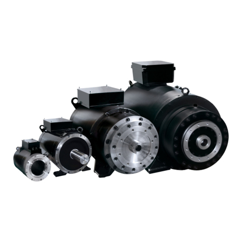
Baumuller DSP1 Series User manual

TAM 00746 1
DSP1 045 - 100 11 / 2019
Three phase synchronous motor English
TAM 00746
DSP1 045 - 100
Three phase synchronous motor
Version: 11/2019
English
Operating manual
including the safety
instructions

TAM 00746 2
DSP1 045 - 100 11 / 2019
Three phase synchronous motor English
LEGAL NOTES ON THE DOCUMENTATION
Copyright
This documentation may be copied by the owner solely for the internal use in any number. No
part of this documentation may be copied or reproduced for any other purpose. Use and
communication of the contents of this documentation are not permitted. Designations or
company symbols in this documentation may be trademarks whose use by third parties for
their own purposes may infringe the rights of their owners
Obligation
This documentation is part of the equipment/machine. These commissioning and mainte-
nance instructions must be accessible to the operator at all times and in a legible condition.
If the equipment/machine is sold or relocated, this documentation must be passed on by the
owner together with the equipment/machine. After the device/machine has been sold, this
original and all copies must be handed over to the buyer. After disposal or other end of use,
this original and all copies must be destroyed.
With the handing over of the present documentation corresponding documentations with an
earlier status are invalidated.
Please, note that the data/figures/information are current values at the date of printing.
These data are not legally binding for measurement, calculation and calculations.
Baumüller Nürnberg GmbH reserves the right to change the technical data and handling of
Baumüller products within the scope of its own product development.
However, no warranty can be given for the accuracy of this documentation, unless otherwise
described in the General Terms and Conditions of Sale and Delivery.
BAUMÜLLER NÜRNBERG GmbH
Motor Business Division
D-90482 Nürnberg
www.baumueller.de

TAM 00746 3
DSP1 045 - 100 11 / 2019
Three phase synchronous motor English
Content
1General Safety Notes..........................................................................................4
1.1 Safety........................................................................................................................................4
1.2 Intended use..............................................................................................................................5
1.3 Prohibition of unauthorized modifications and alterations.........................................................6
2Operating conditions..........................................................................................6
2.1 Product description....................................................................................................................6
2.2 Scope of delivery.......................................................................................................................7
2.3 Type plate..................................................................................................................................7
2.4 Technical data...........................................................................................................................8
2.5 Transport, shaft lock, temporary storage ..................................................................................9
2.6 Installation conditions, cooling data.........................................................................................10
2.7 Balancing, output elements, vibrations....................................................................................11
3Mounting............................................................................................................13
3.1 Safety notes ............................................................................................................................13
3.2 Setting up and fixing................................................................................................................13
3.3 Vibrations and vibration resistance .........................................................................................14
4Electric connection...........................................................................................16
5Commissioning, operation...............................................................................18
5.1 Safety notes ............................................................................................................................18
5.2 Tests before commissioning...................................................................................................18
5.3 Commissioning, operation.......................................................................................................19
5.4 Failures....................................................................................................................................20
6Inspection and maintenance............................................................................22
6.1 Inspection................................................................................................................................22
6.2 Maintenance............................................................................................................................22
7Disposal.............................................................................................................22
8Appendix 1: Pole assignments (power and control connections)................23
8.1 Main connection via the plug...................................................................................................23
8.2 Main connection via terminal box (standard version according to the catalogue)..................23
8.3 Main connection via terminal box (customer-specific version according to EN 60034; not UL-
approved)................................................................................................................................24
8.4 Main and control connection via combination mounting socket (customer-specific version)..25
8.5 Fan connection 24 V DC / 115 V AC / 230 V AC ....................................................................26
8.6 Control connection: Resolver..................................................................................................26
9Appendix 2: Version with water cooling.........................................................27
9.1 Performance definition for water-cooled machines.................................................................27
9.2 Motor cooling...........................................................................................................................27
Mounting notes ..........................................................................Fehler! Textmarke nicht definiert.
9.3 Electric connection..................................................................................................................28
9.4 Information on the required coolant volume rate of flow.........................................................29
9.5 Cooling water quality...............................................................................................................30
9.6 Minimum coolant temperature in dependance of the ambient conditions...............................30
9.7 Operating malfunctions ...........................................................................................................32
9.8 Inspektion................................................................................................................................32

TAM 00746 4
DSP1 045 - 100 11 / 2019
Three phase synchronous motor English
1 General Safety Notes
1.1 Safety
This electric motor has been built in accordance with the current state of safety technology and its
operational safety has been checked before leaving the factory.
For proper commissioning and safe use, please observe the following:
The commissioning and maintenance instructions and the supplementary parts enclosed
with them
The enclosed safety and commissioning instructions
The technical documentation of the product
The commissioning and safety notes of the manufacturer of the converters
The national, local and system-specific regulations for your end product
The technical instruction TAM 00697 during the use in safety-related applications
Refer to the following danger sources during the use of this product:
Danger due to
Lifting and transport operations
Electric current
Moving parts
Hot surfaces
EMC disturbances
Mechanical overload
Thermal overload
In order to avoid endangering persons and property or to minimize any residual risks, please
observe all safety instructions, in particular those marked with symbols.
Danger to life from electric current
Nonobservance may result in death or serious injury.
Warning of general dangers
Nonobservance may result in serious injury or property damage.
Warning of a dangerous situation
Nonobservance may result in damage to the system or the environment
Prohibition of contact
Nonobservance may result in serious injury.
Prohibition of an improper action
Nonobservance may result in serious injury.
Warning of hot surface
Nonobservance my result in serious injury.
Warning of magnetic field
Nonobservance may result in serious injury or property damage.
Electrostatically sensitive parts
Nonobservance may result in damage to the system or the environment.

TAM 00746 5
DSP1 045 - 100 11 / 2019
Three phase synchronous motor English
1.2 Intended use
The use of the electric motor is permitted only within its intended use. In this context, the electric
motor may only be used for the applications specified in the technical documentation, observing all
instructions in these commissioning and maintenance instructions.
All work relating to installation, commissioning, maintenance and during operation may only be car-
ried out by qualified personnel.
In the sense of the safety information given here, qualified personnel means a person trained and
authorized in the field who is authorized to install, assemble, commission and operate devices, sys-
tems and circuits in accordance with the applicable safety standards (EN 50110-1).
Improper behaviour can cause serious personal injury and damage to property.
This electric motor is intended for the use in commercial systems and is subject to the following
standards and guidelines:
Standards
EN 60034-1, EN 60034-5, EN 60034-6, EN 60034-7, EN 60034-9, EN 60034-11, EN 60034-14
EN 60204-1
EU Low Voltage Directive
Electric motors of this series meet the requirements of the Low Voltage Directive (2014/35/EU (con-
formity).
EU Machinery Directive
Electric motors are components for installation in machines within the meaning of the Machinery Di-
rective. Commissioning is prohibited until the conformity of the end product with this directive has
been established (observe EN 60204-1 "Electrical equipment of machines").
EU EMC Directive
The operation of the electric motor in its intended use must meet the protection requirements of the
EMC Directive 2014/30/EU. Proper installation (e.g. spatial separation of signal lines and power ca-
bles, shielded lines and cables, etc.) is the responsibility of the installer of the system and the sys-
tem provider. In converter operation, the EMC instructions of the converter, encoder and brake
manufacturer must also be observed.
In addition, observe the binding national, local and plant-specific regulations!
The electric motor is designed for the following ambient conditions:
Ambient temperature: 0 °C to +40 °C
Altitude: 1000 m above sea level
Relative humidity: 5 % to 85 %
Observe any deviating information on the type plate or in the technical documentation. The condi-
tions on site must comply with all specifications on the type plate.
The use in hazardous areas is prohibited unless expressly provided for. (Observe
additional instructions) There must also be no combustible gas mixtures or dangerous
dust concentrations in the vicinity of the electric motor. Live and hot motor parts could
inflame itself and cause serious injuries and material damage.
If in special cases - in use in non-commercial systems - increased requirements are
placed (e.g. protection against contact with children's fingers), these conditions must
be ensured by the system during installation.

TAM 00746 6
DSP1 045 - 100 11 / 2019
Three phase synchronous motor English
Motor version with rare earth magnet:
In the vicinity of an attracted drawn or open rotor with a strong magnetic field, the fol-
lowing dangers should be noted:
Persons with electronic or metallic implants (e.g. pacemakers, hearing aids,
plates or nails) are at risk if the distance between the implant and the magnetic
pole is less than 0.5 m.
Due to strong forces of attraction to ferromagnetic parts:
oRisk of injury due to crushing
oRisk of destruction of measuring and assembly tools, credit cards, watches, etc.
oContamination of the rotor package by attracted metal chips or powder
Thermal danger:
Caution –Danger of burns!
Surface temperatures of over 70 °C can occur on the motors. If necessary, protective
measures against accidental contact must be provided.
No temperature-sensitive parts, such as normal cables or electronic components, may
touch or be attached to hot surfaces.
Thermal overload of the motors can lead to destruction of the winding, the bearings
and to demagnetization of the rare earth magnets. Use the temperature sensor for
temperature control.
1.3 Prohibition of unauthorized modifications and alterations
For safety reasons, any unauthorized modifications and alterations to the electric motor
are not permitted. If necessary, please contact the motor manufacturer.
In general, safety devices may not be disassembled or put out of operation to operate
the electric motor
2 Operating conditions
2.1 Product description
Baumüller completes the existing DSC range by the new DSP1-series 045-100 used for applica-
tions with high speed requirements up to 6.000 min-1.
By an increased speed range and a good acceleration and overload capability at the same time this
DSP motor series is especially well suited for applications in handling axes, processing machines
and servo pump drives.

TAM 00746 7
DSP1 045 - 100 11 / 2019
Three phase synchronous motor English
2.2 Scope of delivery
The delivery is arranged according to the order.
If transport damage is found on delivery, this must be reported directly to the transport
company.
Upon receipt of the delivery, immediately compare the performance data and designs of the
motor supplied with your order data. If recognisable defects or an incomplete delivery are
found, the responsible regional office of Baumüller or the main plant in Nuremberg are to
be informed.
In both cases, commissioning of the motor is prohibited until the defect has been professionally re-
moved.
2.3 Type plate
The type plate is the identifier for each electric motor. In particular, the respective motor number is
unique for each electric motor and absolutely necessary for the traceability in our company. The
type plate must therefore be legible at all times. Never remove the type plate from your motor.
Type plate data:
Bild1:Typenschild
1
Motor number
2
Standards and approvals
3
Motor type / designation
4
Motor protection type
5
Thermal class (insulation material class
designation VDE)
6
Motor type: AC motor
7
Permissible ambient temperature
8
Rated frequency
9
Insulation system UL
10
Motor operating type
11
Rated voltage UN
12
Standstill torque M0
13
Standstill current I0
14
Rated speed nN
15
Rated power PN
16
Order number
17
Vibration quality factor
18
Synchronous generatede voltage
19
Barcode

TAM 00746 8
DSP1 045 - 100 11 / 2019
Three phase synchronous motor English
2.4 Technical data
Types (EN 60034-7) IM B5 Mounting position horizontal
IM V1 Mounting position vertical, shaft end downwards
IM V3 Mounting position vertical, shaft end upwards
Note: For mounting position IM V3 in conjunction with protection class IP 64, the shaft
passage must be protected against ingress of water and dirt.
Protection class (EN 60034-5) In consideration of the shaft feedthrough
IP 64 Standard: Without a shaft sealing ring
IP 65 Option: With a shaft sealing ring
Without consideration of the shaft feedthrough
IP 67 for the self-cooled version (IC 410 and
IC 3W7); not for motors with terminal box
IP 65 for surface-cooled version (IC 416)
IP 65 for version with terminal box
Attention: All listed protection types are only achieved with completely assembled plug
connections (main and control connection) and by a completely closed terminal
box.
Cooling method (EN 60034-6) IC 410 Standard:
completely closed motor version,
self-cooled without fan
IC 416 Option: From an axis height of 56
completely closed motor,
surface-cooled with fan,
Air flow direction from B to A side of the motor
IC 3W7 Option:
completely closed motor,
water-cooled,
Cooling circuit connections in direction
Electrical connections (see appendix) via angled (3x90°) rotatable installation boxes
Attention: For standstill currents I0> 36 A, the main connection is made via terminal
boxes
Main connection 8-pole mounting box / terminal box
Standard: U V W + Temperature sensor
Option: Brake
Control connection 12-pole Standard: Resolver
Fan (optional) 6-pole
Thermal motor protection (EN 60034-11) Temperature sensor PT1000 in the stator winding
Winding insulation (EN 60034-1) Thermal class F (Δθ = 105 K)
Ambient temperature 0 °C… +40 °C (standard)
Altitude (EN 60034-1) ≤1000 m above sea level (standard)
Rolling bearings with permanent grease
lubrication Standard: Deep groove ball bearing
Option (from size 56): Cylindrical roller bearing (A-
side)
Calculated bearing operating life LH10 20.000 h (approximate value)

TAM 00746 9
DSP1 045 - 100 11 / 2019
Three phase synchronous motor English
Vibration quality (EN 60034-14) Standard: A
Special: B (with deep groove ball bearing)
Concentricity (DIN 42955) Standard: N
Special: R (reduced)
Vibrations and resistance to vibrations radial 3 g / axial 0,5 g 10 Hz to 100 Hz
(refer to point 3.3)
Holding brake Option
Actual speed encoder Standard: 2-pole resolver
(high-quality version on request)
Further characteristics can be found in our technical product list on the website: www.baumueller.de
in the download area under Technical documentations. If necessary, request the corresponding
documents.
Attention!
If the electric motor supplied does not correspond to the standard version according to the technical
list or if special contractual agreements have been made, technical deviations from these commis-
sioning and maintenance instructions may exist. In this case, ask for the corresponding technical
supplements.
2.5 Transport, shaft lock, temporary storage
Water-cooled motors:
To avoid frost damage, ensure that no coolant is present in the engine during transport
or temporary storage at ambient temperatures < 3 °C.
Transport:
The permissible environmental conditions which may affect the motor during transport
can be found in DIN EN 60721-3-2 (class 2K2/2M1).. Contrary to DIN, the permissible
temperature range is reduced to - 15 °C to + 60 °C.
Appropriate load handling equipment must be used, such as webbing, loop lifting
straps, etc. The lifting lugs of the motor can also be used for lifting, if provided.
During transport, the respective country-specific regulations must be observed.
Lifting equipment, transport and load handling devices must comply with the
regulations.
Please refer to the product's technical documentation for the weight specifications of the individual
electric motors.
The motor shaft and the connection surfaces must be protected against corrosion. The motor may
only be transported with a shaft protection cover. Damage to the motor shaft must be avoided.

TAM 00746 10
DSP1 045 - 100 11 / 2019
Three phase synchronous motor English
Shaft protection: (only for motors with cylindrical roller bearings)
In order to avoid transport damages the motors with cylindrical roller bearings of the
rotors are blocked at the shaft end by a transport lock.
This transport lock must be reused for further transports.
If this safety device can no longer be used due to an output element, other suitable
measures for axial fixation of the rotor must be taken during transport
Temporary storage:
If an engine is not commissioned directly after delivery, it must be stored in a dry, low-dust, low-
vibration interior space (Veff ≤ 0.2 mm/s).
The electric motors should not be stored for longer than max. 2 years at a preferably even tempera-
ture, not outside the temperature range of -15 to +60 °C. Higher storage temperatures within the
operating temperature range accelerate the ageing process of the seals and bearing greases and
thus have a negative effect on the service life even before commissioning. Direct sunlight, UV light
and ozone also contribute to ageing of the sealing elements and must therefore be avoided under
all circumstances!
Please note that the warranty periods are guaranteed from the date of delivery. Therefore we rec-
ommend to limit the storage time to a minimum.
Should a longer storage period nevertheless be unavoidable, the environmental conditions listed in
DIN EN 60721-3-1 (Class 1K2/1M1) must be observed. Contrary to the DIN, the temperature range
may be extended to - 15 °C to + 60 °C.
2.6 Installation conditions, cooling data
For motors with water cooling, please also refer to chapter 9.
Environment:
The motor can be installed in roofed rooms according to its degree of protection (refer to motor rat-
ing plate) in a dusty or humid environment.
If no special agreements have been made, the drive is designed for the following climatic operating
conditions as a standard:
Ambient temperature 0 °C to 40 °C
Installation altitude ≤1000 m above sea level
Relative humidity 5% to 85%.
All other permissible operating conditions can be found in DIN EN 60721-3-3 (class 3K3/3Z12).
These climatic conditions must be observed during installation.
It is generally necessary to keep aggressive, corrosive, abrasive as well as plastic dissolving media
away from the motor and its cooling air.
For outdoor installation, always consult the motor manufacturer.

TAM 00746 11
DSP1 045 - 100 11 / 2019
Three phase synchronous motor English
Air cooling:
Also refer to chapter 2.4 and technical documents referring to the product.
Cooling process IC 410 –Self-cooling without fan
Cooling process IC 416 –Surface-cooling with fan
In general please observe the following:
Thermal convection and radiation must not be affected by the installation conditions.
The cooling air with forced air cooling must be able to flow in unhindered and the warm air
must be able to flow out freely. The heated exhaust air must not be drawn in again.
The distance to the neighboring machine parts should not be less than 100 mm.
In case of heavy dirt accumulation, the housing surface and the air passages must be
cleaned regularly.
Flange connection:
By coupling the motor to the mounting surface, part of the motor power loss is dissipated via the
flange.
The table 1 below lists the dimensions of the mounting surfaces, depending on the axis height.
These specifications are minimum values for a reliable heat dissipation via the motor flange surfac-
es.
Axis height
Steel plate:
Width x Height x Thickness in mm
Mounting area
in m2
45
250 x 250 x 10
0,06
56 –100
450 x 400 x 30
0,18
Table 1: Mounting area
The heat dissipation conditions improve with larger mounting areas. An insulated mounting of the
motors is not permitted.
2.7 Balancing, output elements, vibrations
Do not impact the shaft and bearing!
When mounting or dismounting output elements, axial forces on the motor are not
permitted.
The general measures required to protect the output elements against contact must be
observed.
If a motor is commissioned without an output element, the feather key must be se-
cured against ejection.
Balancing:
In the optional version with feather key, the rotors are dynamically balanced as standard with
half feather key. (according to EN 60034-14 / ISO 8821 / ISO 1940)
NOTE: Observe the marking of the balancing type on the shaft end face and type plate!
H = Balancing with half key (standard)
F = Balancing with full key (special version)
N = Balancing without feather key (special version)

TAM 00746 12
DSP1 045 - 100 11 / 2019
Three phase synchronous motor English
Output elements:
When mounting the output element, pay attention to the corresponding type of balancing.
The output elements themselves must be balanced according to ISO 1940.
When mounting or dismounting output elements (e.g. clutch disc, gear wheel, pulley),
appropriate devices must always be used.
Use a threaded hole in the shaft end.
Use intermediate disks for mechanical protection of the shaft when removing.
If necessary, heat the output elements before mounting (max. permissible temperature
at shaft end 150 °C for a short time)
Attention!
For shaft versions without feather key, the output elements must be fastened to the out-
put shaft using suitable clamping sets.
For shaft versions with feather key, make sure that the output elements are in contact
with the shaft shoulder. Note: Chamfer or radius at the output element and the shaft
radius to the shoulder must be matched to one another.
If the threaded hole in the shaft end is used for axial securing of output elements (such
as belt pulleys), the tightening torques listed in Table 2 below must not be exceeded:
Threads
Tightening
torque
in Nm
M5
2,2
M8
10,0
M10
19,0
M12
33,0
Table 2: Tightening torques shown with a safet bolt S of a pulley
Appropriate measures for screw locking are to be applied!
Vibrations:
The system vibration behavior at the place of use, due to output elements, mounting
conditions, alignment and installation as well as by influences of external vibrations,
can lead to an increase in the vibration values at the motor.
In order to ensure proper functioning of the motor and a long bearing life, the permissi-
ble vibration values according to EN 60034-14 must not be exceeded. Under certain
circumstances, it may be necessary to completely balance the rotor with the output
element (according to ISO 1940).
The limited vibration loads and accelerations after mounting must not be exceeded,
refer to chapter 3.3.
In case of changes compared to the normal operation, such as increased tempera-
tures, noises, vibrations, the motor must be switched off in case of doubt, the cause
must be determined and, if necessary, the manufacturer must be consulted.
S

TAM 00746 13
DSP1 045 - 100 11 / 2019
Three phase synchronous motor English
3 Mounting
3.1 Safety notes
Before mounting:
Never mount or operate a damaged electric motor.
Never install an electric motor in a damged machine.
Before installing, make sure that the electric motor for your machine is appropriate.
During mounting:
Mount the motor only at the mounting points provided for this purpose.
Avoid strokes with a hammer or impermissible shock loads during installation.
Install all covers and safety devices. All safety devices must comply with the applicable
regulations (e.g. EN 60204).
Air cooling:
Protective devices must be fitted to the air inlet and outlet openings if there is a possibil-
ity that foreign particles could fall into the fan during operation.
3.2 Setting up and fixing
Check before and during mounting whether
the motor is undamaged (e.g. the shaft seal must not be damaged in any way by sharp
or pointed objects).
the motor is not installed in the danger area of other equipment.
the intended use is observed (see chapter 1.2, chapter 2.4)
Observe type plate specifications, warning and information signs.
the corrosion protection agent at the shaft end has been removed residue-free.
If commercial solvents such as acetone or benzine are used, the shaft sealing ring must
not be wetted!
the motor is suitable for the ambient conditions and environmental influences on site
(compare chapter. 2.4).
the installation space in the machine is suitable for the type of cooling of the electric mo-
tor
The motor must be mounted in such a way that sufficient heat dissipation is ensured via
the housing surface and the motor flange surface (compare chapter 2.6).
the motor can be mounted and operated with the available mounting options and con-
nection data.
The installation dimensions of the motor with tolerance specifications can be found in
the technical documentation for the product. When flange-fixing the motor, care must be
taken to ensure that the flange surface is well and evenly supported. The mounting
seats and contact surfaces must be undamaged and clean. They should be positioned
exactly to the connecting shafts in order to avoid damaging loads in the overall system
due to misalignment for bearings, shafts and housing. When tightening the flange fixing
screws (at least in strength class 8.8), twistings on the flange connection must be
avoided.
when installed vertically with the shaft end pointing upwards, it is ensured that no liquid
can enter the upper bearing.
the permissible radial forces are not exceeded in accordance with the operating charac-
teristics of the technical documentation for the product (clarification via the Baumüller-

TAM 00746 14
DSP1 045 - 100 11 / 2019
Three phase synchronous motor English
subsidiary, if required).
In the case of axial forces, clarification with the motor manufacturer is always required.
the brake (optional) can be released after the operating voltage has been applied (audi-
ble switching noise).
the rotor can be rotated evenly and without any streaking noises.
If the motor has an integrated brake, first release the brake.
the design of the motor, encoder and fan lines, if any, comply with the requirements of
the technical documentation for the product.
The output or drive elements are protected.
the complete cooling system is functional and protected against any foreign particles
falling into it.
3.3 Vibrations and vibration resistance
The vibration behavior of the entire system at the place of use, due to output elements, mounting con-
ditions, alignment and installation as well as by influences of external vibrations, can lead to an in-
crease in the vibration values at the motor.
Under certain circumstances it may be necessary to completely balance the rotor with the output ele-
ment.
In order to be able to guarantee perfect function and service life, the vibration values specified in ac-
cordance with DIN ISO 10816 must not be exceeded at the specified measuring points of the motor
(see Figure 1).
Figure 1: Measuring points for vibration measurement
The specified maximum radial and axial vibration values must be complied to simultaneously. They
apply to substructures that can be described as elastic. An elastic substructure is present if the lowest
natural frequency of the overall system (machine and foundation) in the measuring direction is at least
25% below the essential excitation frequency. All other structures can be described as rigid. In the
case of rigid substructures, the manufacturer must be consulted.

TAM 00746 15
DSP1 045 - 100 11 / 2019
Three phase synchronous motor English
Maximum radial vibration load:
Peak vibration acceleration 1 g > 250 Hz
Peak vibration displacement ≤ 0,16 mm < 6,3 Hz
Effekt. Vibration speed: ≤ 4,5 mm/s 6,3 Hz –250 Hz
Figure 2: Permitted radial vibration load
Maximum axial vibration load:
Peak vibration acceleration 0,225 g > 55 Hz
Peak vibration displacement ≤ 0,16 mm < 6,3 Hz
Effect. Vibration speed ≤ 4,5 mm/s 6,3 Hz –55 Hz
Figure 3: Permitted axial vibration load
Additional vibration resistance:
Vibration acceleration 3 g radial and 0.5 *** g axial 10 Hz to 100 Hz
The specified vibrations are additionally tolerated by the motor. However, the service life of wear parts
(such as bearings) can be reduced.
Shock stress:
If there are increased vibration loads in the form of shocks, measurements on the installed machine
are necessary.

TAM 00746 16
DSP1 045 - 100 11 / 2019
Three phase synchronous motor English
Based on this, design revisions or evaluations are carried out with the company Baumüller.
To evaluate the vibration speed, the measuring equipment shall meet the requirements of ISO 2954.
The vibration acceleration shall be evaluated in the time range in the frequency band from 10 Hz to 2
kHz.
If significant vibration excitations above 2 kHz, e.g. meshing frequencies, are to be expected, the
measuring range must be adapted accordingly. The permissible maximum values do not change as a
result.
4 Electric connection
Important notes:
All work must be carried out by qualified personnel, only!
All work must only be carried out with the system disconnected from the power supply
and secured against reconnection! (also auxiliary circuits).
Carry out all work only when the motor is at a standstill!
With three-phase synchronous motors with permanent magnet excitation, voltages > 60 V may
occur at the motor contacts when the rotor is rotating.
Observe the regulations for work in electrical systems!!
Attention! The safety regulations for work in electrical systems according to EN 50110-1 must
be observed.
Enabling
Protect against restarting
Determine the safe isolation from supply
Grounding and short-circuiting
Cover or safeguard live parts
The operation of the electric motor is only possible in conjunction with an appropriate
configured converter. Direct connection to the three-phase mains can lead to destruc-
tion of the motor.
The correct phase sequence and terminal assignment must be observed.
The electrical connections, protective conductor connections and shield connections
(when using shielded cables) must be permanently safe
Never touch the contacts of the encoder and the temperature sensors with the hands
or with tools that are or may be electrostatically charged!
Encoders and temperature sensors are electrostatically sensitive components.
Elektrische Installation:
Proper installation is the responsibility of the installer of the system.
The motor data of the type plate must be considered.
Connecting cables and plug connections must be correctly dimensioned for the voltages
and currents occuring and suitable for the type of installation.
The connection of the motor including its modules (brake, encoder, fan etc.) must be
connected according to the wiring diagrams (refer to enclosed wiring diagrams or
chapter 8).
Shielded power and encoder cables must be used to avoid electromagnetic EMC inter-
ference of motor supplies and their consequences for encoders and control systems.
Observe the EMC instructions of the converter manufacturer.
For reasons of operational safety, we recommend the use of connection lines assem-
bled by Baumüller (see Technical Product List)

TAM 00746 17
DSP1 045 - 100 11 / 2019
Three phase synchronous motor English
Before connecting, check the installation boxes, plugs and, if present, the terminal box
for possible damage, corrosion, dirt and moisture.
To ensure the degree of protection, ensure that the plug screw connections, the seals
and sealing surfaces of the plugs and the terminal box are seated correctly and protect-
ed.
Note! To maintain the degree of protection, the turnable connection boxes should not be
changed more than 5 times by turning the knob.
Plug-in and terminal box connections must not be subjected to mechanical stress. If re-
quired provide torsional, tensile and thrust loads as well as a bend protection.
In the case of main connection via the terminal box additionally the following must be consid-
ered:
The cable ends must only be stripped to such an extent that the insulation is close to the
cable lugs or terminals. Absolutely avoid protruding wire ends.
The cable lugs used must correspond to the dimensions and cross-sections of the ter-
minals and cables.
The screw connections of the electrical connections are tightened by the specified tight-
ening torque (refer to 9.2 table 4 /9.3 table 5).
The protection degree remains..
Note! All entries that are not required are closed with metal locking elements. The
sealing elements must be functional and undamaged.

TAM 00746 18
DSP1 045 - 100 11 / 2019
Three phase synchronous motor English
5 Commissioning, operation
5.1 Safety notes
Working on the electric motor:
Perform all works on the electric motor only when the motor is standing still, is deener-
gized and is cooled down. All connections loosened during the work on the electric
motor such as screws etc. must be tightened before commissioning.
When carrying out the work it is essential to observe the technical notes in the reqpec-
tive chapters of this eommissioning and maintenance manual.
Attention!
If the holding brake is installed as an option, it must not take any safety function during
work on the motor (e.g. holding loads).
Danger to life from electric current:
Make sure that the electric motor is disconnected and without voltage.
Never disconnect the connections on the motor during operation.
Only connect measuring instruments when they are currentless and de-energized.
Do not start work on the motor connections until you have ensured that neither poten-
tial nor voltage is present.
During operation, electrical potential is present at the motor contacts and at the motor
windings. Never touch these components/elements during operation.
Assembly and disassembly of safety devices
The electric motor must not be operated without mounted safety devices.
For the assembly and disassembly of components and systems intended to monitor
safe motor operation, the motor must be taken out of operation
Danger of contact:
Make sure that the electric motor is stationary and protected against being switched on
again before touching it.
Touch the output shaft only when the motor is not energized and stopped. Otherwise,
there is a danger from the rotating rotors
Risk of burns! Never touch the motor housing during rated load operation. Surface
temperatures of over 70 °C can occur on the motors.
5.2 Tests before commissioning
The drive is undamaged and is not in the danger zone of other equipment.
The motor is properly aligned and secured. Screw connections are correctly tightened.
All associated protective devices (mechanical, thermal, electrical) are mounted.
The motor connections are properly made.
The cables do not touch the motor surface.
- The protective conductor system is correctly implemented and tested for function
- The drive does not block (release brake, if present).
- Emergency stop functions are checked.
- The fan is properly connected, the functionality has been checked.

TAM 00746 19
DSP1 045 - 100 11 / 2019
Three phase synchronous motor English
5.3 Commissioning, operation
Note on the function of the brake (if available):
The brake is designed as a holding brake with emergency stop function.
(power failure, emergency stop)
The use as a working brake is not permitted..
Commissioning must only be carried out by qualified personnel.
The converter commissioning instructions must be observed.
Tests during commissioning:
Release the brake if necessary.
Have all motor components such as brake, encoder, fan, etc. been checked for function
and are your operating conditions being adhered to?
Have all electrical connections and connections been made and fixed in accordance with
the regulations (observe wiring diagrams, see section 8 or enclosed wiring dia-
grams)?
Have all protective measures been taken and are they working properly to prevent contact
with live parts, hot surfaces, rotating and moving parts and assemblies?
Are all output elements assembled and adjusted according to the manufacturer's specifica-
tions?
- Is it ensured that the max. permissible speed n max of the motor cannot be exceeded? The
max. permissible speed nmax is the highest short-term permissible operating speed
Tests during operation:
-Pay attention to unusual noises.
If there are streaking or scratching noises, grinding noises or similar, shut down the drive
immediately and determine the causes.
Check motor surface and connecting cables for dirt (such as dust deposits, oil contamina-
tion, moisture, etc.).
Check maintenance intervals.
Check air inlet and outlet openings for dirt.

TAM 00746 20
DSP1 045 - 100 11 / 2019
Three phase synchronous motor English
5.4 Failures
Safety notes:
Only qualified personnel should carry out troubleshooting.
Do not disable protective devices - not even during test operation.
Disconnect and reinstall connecting cables only in a voltage-free and protected
condition.
Observe the 5 safety rules for the "Enabling" (see chapter 4)
Pay attention to hot surfaces!
In case of operational failures:
- Observe the operating instructions of the machine / system.
- Observe the operating instructions of the converter.
- If necessary, contact the motor or converter manufacturer.
You should have the following parameters ready:
Type plate data
The type and extent of the disturbance; circumstances of the error
Application cata (cycle of torque, speed and forces over time; ambient conditions)
The following selection of error causes can provide useful assistance for troubleshooting in the
event of a fault:
Error
Error cause
Troubleshooting
Motor does not start
Controller enable is missing
Controller error, encoder error
Brake does not release
Brake defective
Voltage supply is missing
Rotating field
Activate controller enable
Read out error listing on con-
verter or controller,
troubleshooting
Check control, connection and
power supply
Repair by manufacturer
Check connection and power
supply
Check phase sequence, re-
place connecting cables if
necessary
Uneven runningf
Insufficient shielding in the
connecting cables
Controller parameter too high
Check shield connection and
earthing
Optimize controller parame-
ters
This manual suits for next models
2
Table of contents
Other Baumuller Engine manuals

Baumuller
Baumuller DSM1 Guide

Baumuller
Baumuller DS 100 Guide

Baumuller
Baumuller DSC1-045-100 Series User manual

Baumuller
Baumuller GNA 100 User manual

Baumuller
Baumuller DA 100 Guide

Baumuller
Baumuller DST2 Series Installation instructions

Baumuller
Baumuller DA 100 Guide

Baumuller
Baumuller DSD-028 Guide

Baumuller
Baumuller DSD 45 Guide

Baumuller
Baumuller DSD2 Series Guide