9 10777 - GB-CZ-HU-PL-RO-RU - 0 - 04 / 07
Two stage burner
- Adjusting the backflow air (flap)
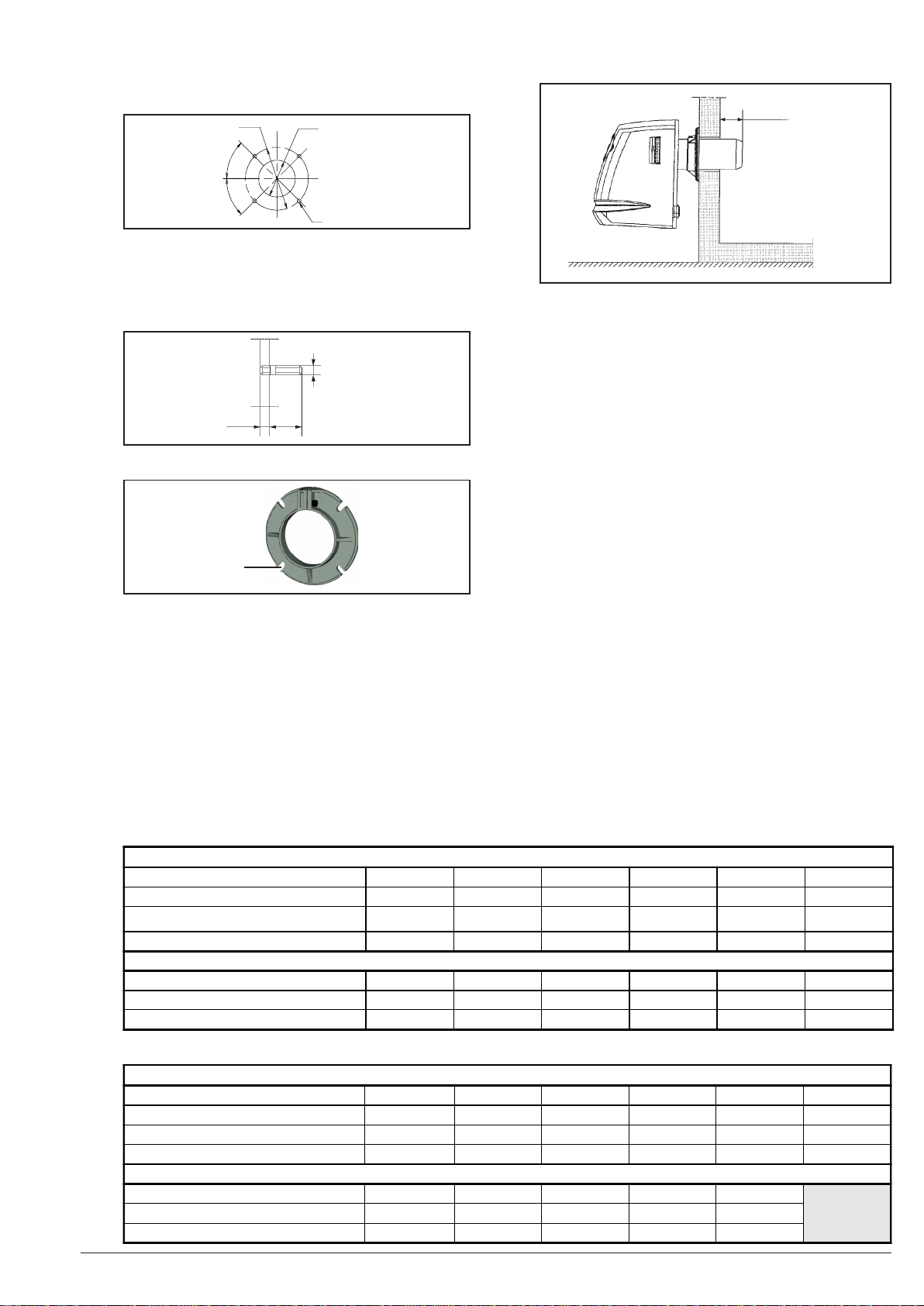
- Servo moteur SQN 71 description:
1 red cam (I), 2nd rate cam,
2 blue cam (II) closing cam at stoppage,
3 orange cam (III) 1st rate cam,
4 black cam (IV) valve opening cam,
5 cam position angular marking,
6 shaft release button,
7 red and black cam adjustment key.
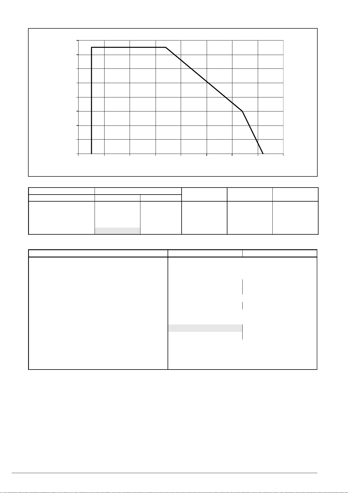
6.5 Oil pressure setting
- Switch on the burner. The programming unit indicator light (reference D) goes on, the fan starts (immediately if the burner
is “not reheated”) 50 seconds after switch on (if the burner is “reheated”). The burner ignites after 15 seconds of preliminary fanning.
- Using the setting screw (reference Q) set the fuel pressure by reading the value on the pressure gauge installed on the
pressure intake (reference K).
6.6 Combustion control
In principle this is controlled using an analyser with the burner cover on. If for convenience you have to work with the burner
cover off, the CO2measured should be 0.3 to 0.5% below the desired values (12 to 13% CO2).
- Shipping position: remove the servomotor cover. To
prevent damaging the air flap, the burner is
supplied with the servomotor set to position 0 (blue
cam).
- When powering on the burner, set the blue cam to
position 0 (screwdriver).
- Setting the 2nd air rate: after burner ignition, the
servomotor shifts to 2nd rate position. (setting
devices in demand). If required, fine tune this
setting by turning the red cam (130°) (adjustment
key).
- Setting the shift into 2nd rate: turn the black cam.
Set it upstream the 2nd rate cam (between the red
cam and orange cam, and very close to it) to
ensure the valve opens before full opening of the air
flap (adjustment key).
- Setting the 1st rate: fine tune this setting by turning
the orange cam (65° to 70°) (screwdriver).
- Suction air setting (intake): see the one stage burner
567
1234
Case CO2Smoke Corrective action
One stage burner
0 12 to 13 ST = 0 No change
1 12 to 13 ST > 1 Check the settings parameters. Check the seal between the nozzle, boiler and chimney and
boiler door tigtness. Check the nozzle penetration in heating chamber. If the parameters are
correct, change the nozzle.
2CO
2>13 TTurn the button (reference V) to open the internal air flow regulator 1 or 2 notches (e.g. 3
to 4.5) to obtain CO2between 12 and 13%. Check the ST (if ST > case N° 1 return).
Check cold starting.
3CO
2< 12
Turn the button (reference V) to close the internal air regulmator 1 or 2 notches (e.g. 3 to 2).
If the CO2stays below 12 close the intake half a graduation (e.g. 8.5 to 8) and the refore
next to obtain CO2between 12 and 13%. Check the ST (if ST > 1 case N° 1 return).
Check cold starting.
Two stage burner
Adjusting the line (without touching the suction
intake) (2nd rate only) Air flap setting (without touching the line)
(1st rate only)
0 12 to 13 ST = 0 No change
1 12 to 13 ST > 1 Check the settings parameters. Check the seal between the nozzle, boiler and chimney and
boiler door tigtness. Check the nozzle penetration in heating chamber. If the parameters are
correct, change the nozzle.
2CO
2>13 Move the line backward by one increment,
by turning the ""L"" screw towards ""+"" and
check combustion.
Open the flap, by turning the orange cam on
the servomotor and check combustion.
3CO
2< 12 Move the line forward by one increment, by
turning the ""L"" screw towards ""-"" and
check combustion.
Close the flap, by turning the orange cam on
the servomotor and check combustion.
Boiler power (92% output) 80 90 95 100 105 110 115 120 125 130 135 140
One stage burner
DELAVAN 60° B nozzle 1.75 2.00 2.00 2.25 2.25 2.25 2.50 2.50 2.75 2.75 2.75 3.00
Pump pressure (bar) 11.0 10.8 12.0 10.6 11.7 12.8 11.3 12.3 11.1 12.0 12.9 11.6
Two stage burner
DELAVAN 60° W nozzle 1.25 1.35 1.50 1.50 1.75 1.75 1.75 2.00 2.00 2.00 2.25 2.25
Pump pressure (bar) 22.6 24.4 22.2 24.6 20.1 22.1 24.1 20.3 22.0 23.8 20.4 21.9