Baxi Solargen PHOTOVOLTAIC User manual

Solargen
Please read these instructions before installing or commissioning.
This Solar Photovoltaic system should only be installed by a competent person.
PLEASE LEAVE THESE INSTRUCTIONS WITH THE USER FOR SAFE KEEPING.
PHOTOVOLTAIC MANUAL
© BAXI Heating UK Ltd 2011


Solargen solar PV 3
Index.........................................................................................................................
Table Index................................................................................................................
Figure Index..............................................................................................................
Safety information.....................................................................................................
1.INTRODUCTION...................................................................................................
1.1.Preface...............................................................................................................
1.2.Supply and Packaging........................................................................................
1.3.Security Warnings...............................................................................................
1.4.Installation Standards.........................................................................................
1.4.1. Safety and Care..............................................................................................
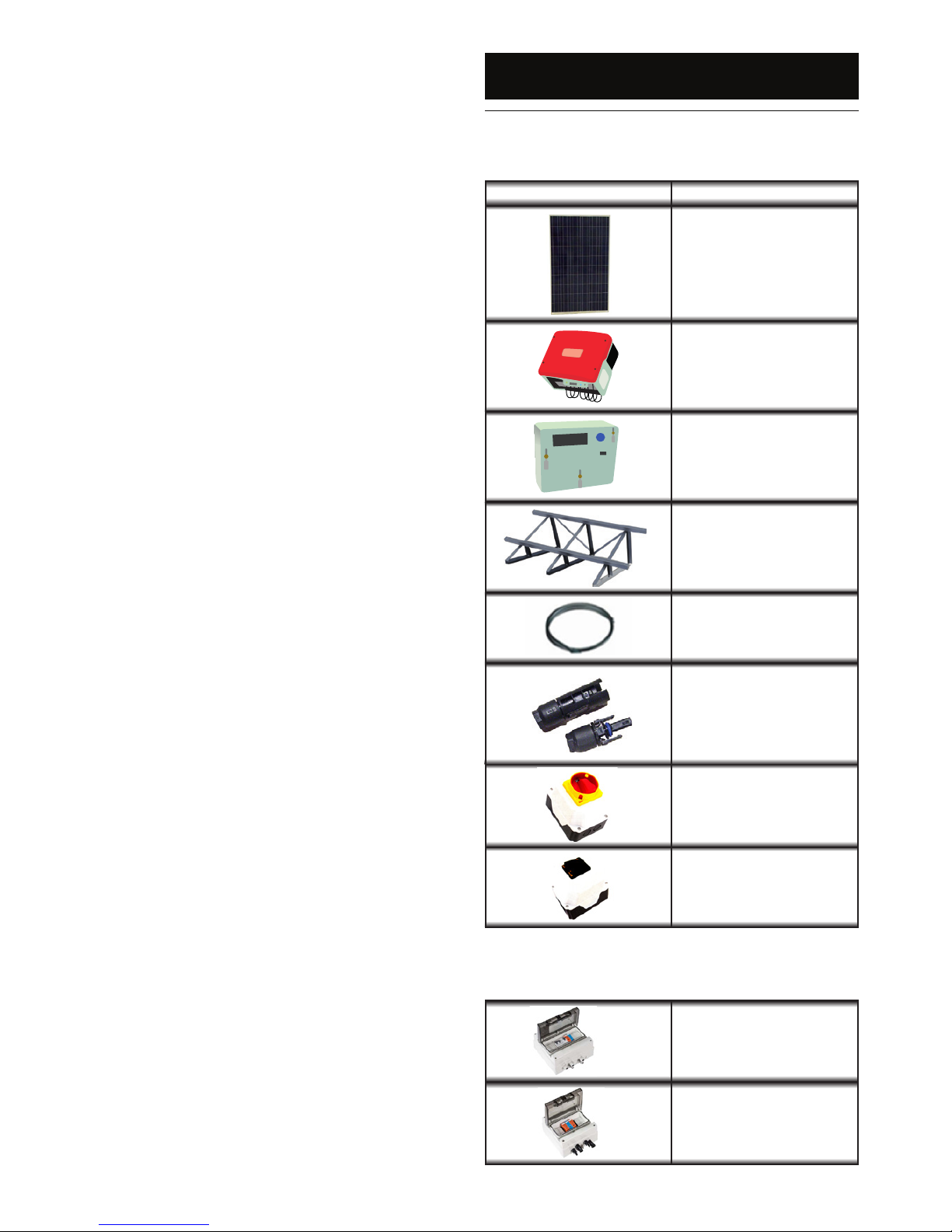
2.KIT CONTENTS..................................................................................................
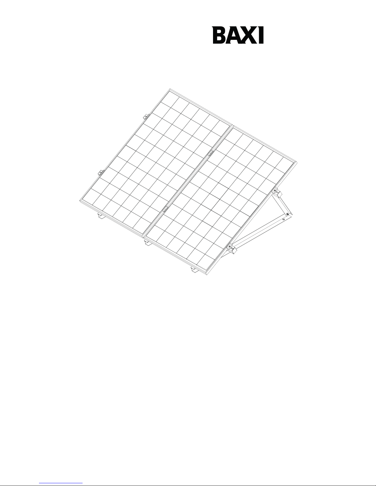
3.PV KIT INSTALLATION.......................................................................................
3.1.PV module........................................................................................................
3.1.1.Choosing the site...........................................................................................
3.1.2.Installation guidelines.....................................................................................
3.1.3.Mechanical characteristics..............................................................................
3.1.4 Mechanic Installation.....................................................................................
3.2.PV Generator....................................................................................................
3.2.1.PV series connection.....................................................................................
3.2.2.PV module fastening......................................................................................
3.3.DC Electric Box (available as an optional extra)...............................................
3.3.1.Components....................................................................................................
3.3.2.Location..........................................................................................................
3.3.3.Electric Scheme.............................................................................................
3.3.4.Crimp connectors...........................................................................................
3.4.Inverter..............................................................................................................
3.4.1.Installation requirements................................................................................
3.4.2.Clearances.....................................................................................................
3.4.3.Position..........................................................................................................
3.4.4.Mounting the inverter.....................................................................................
3.4.5.Connecting PV strings to the inverter.............................................................
3.5. AC electric box (available as an optional extra)...............................................
3.5.1.Description.....................................................................................................
3.5.2.Location..........................................................................................................
3.5.3.Single line diagram.........................................................................................
3.6.Connection to the grid.......................................................................................
3.6.1.AC cable size.................................................................................................
3.7.Energy meter.....................................................................................................
3.7.1.Warnings........................................................................................................
3.7.2.Environmental requirements..........................................................................
3.7.3.Cabling...........................................................................................................
3.7.4.Cable specication.........................................................................................
3.7.5.Installation data..............................................................................................
3.7.6.Dimensions and mounting..............................................................................
3.8.Electrical diagrams............................................................................................
4.PV SYSTEM PROTECTION................................................................................
4.1.Protection against lightening.............................................................................
4.1.1.Array Frame Earthing Decision Tree..............................................................
4.2.Protection against direct contact.......................................................................
4.3.Protection against indirect contact....................................................................
4.4.Warning and note signs.....................................................................................
4.4.1.Location of the safety labels...........................................................................
5.PV SYSTEM COMMISSIONING..........................................................................
5.1.Connect a PV system........................................................................................
5.2.Disconnect the PV system................................................................................
5.3.Security notes...................................................................................................
6.MAINTENANCE MANUAL.................................................................................
6.1.General information..........................................................................................
6.2.PV generator....................................................................................................
6.3.Inverter.............................................................................................................
6.3.1.Safety Warnings............................................................................................
6.3.2.Inverter operation conditions.........................................................................
7.SUPPORTING STRUCTURE ASSEMBLING MANUAL....................................
7.1.Flat roof............................................................................................................
7.2.Parallel to pitched roof......................................................................................
8.WARRANTY........................................................................................................
9.MAINTENANCE..................................................................................................30
10.NOTES..............................................................................................................31
Index
3
4
5
6
8
8
8
8
8
9
10
11
11
11
11
11
11
12
12
12
13
13
13
13
13
14
14
14
14
15
15
16
16
16
16
16
16
17
17
17
17
17
17
17
18
19
19
19
20
20
20
20
21
21
21
21
22
22
22
22
22
22
23
26
26
29
© Baxi Heating UK Ltd 2011. All rights reserved. No part of this publication may be reproduced or
transmitted in any form or by any means, or stored in any retrieval system of any nature (including
in any database), in each case whether electronic, mechanical, recording or otherwise, without
prior written permission of the copyright owner, except for permitted fair dealing under Copyrights,
Designs and Patents Act 1988.
Applications for the copyright owner’s permission to reproduce or make other use of any part of
this publication should be made, giving any details of the proposed use to the following address:
The Company Secretary, Baxi Heating UK Ltd, Brooks House, Coventry Road, Warwick CV34 4LL.
Full acknowledgement of author and source must be given.
WARNING: Any person who does any unauthorised act in relation to a copyright work may be
liable to criminal prosecution and civil claims for damages.

Solargen solar PV
4
Table index
Index
Table 1. Equipment contained within the photovoltaic kit...................................
Table 2. Equipment available as an optional extra.............................................
Table 3.
Table 4. Inverter installation – Minimum distances.............................................
Table 5. AC cable cross sections.......................................................................
Table 6. Relation between the kits and the inverter power................................
Table 7. Maximum earth resistance....................................................................
Table 8. Spacing between A-frames..................................................................
Table 9. Spacing between the roof supports.....................................................
10
10
11
14
16
18
20
23
27
Mechanical specications.....................................................................

Solargen solar PV 5
Index
Figure 1. Handling.................................................................................................
Figure 2. Fastening the modules to the roof mountings.......................................
Figure 3. Module´s physical dimensions..............................................................
Figure 4. Module Fixing........................................................................................
Figure 5. Cable Routing.......................................................................................
Figure 6. PV module junction box........................................................................
Figure 7. PV series connection............................................................................
Figure 8. Diagram for the module´s ground connection......................................
Figure 9. Example of PV mounting......................................................................
Figure 10. DC Electric Box.....................................................................................
Figure 11. DC Electric Box location.......................................................................
Figure 12. Correct crimping pliers..........................................................................
Figure 13. Example of a single line scheme for the DC Electric Box.....................
Figure 14. Inverter installation – requirements.......................................................
Figure 15. Minimum distances...............................................................................
Figure 16. Mounting position..................................................................................
Figure 17. Mounting the inverter............................................................................
Figure 18. Connecting PV strings to the inverter...................................................
Figure 19. AC electric Box.....................................................................................
Figure 20. Example of a single line diagram of the AC electric box.......................
Figure 21. Energy meter.........................................................................................
Figure 22. Meter terminal layout............................................................................
Figure 23. Meter xing points.................................................................................
Figure 24. 1.32 - 2.64 kWp unilar electrical diagram............................................
Figure 25. 3.96 kWp unilar electrical diagram......................................................
Figure 26. Ex. electrical diagram with AC and DC electrical box...........................
Figure 27. PV system protection............................................................................
Figure 28. Array Frame earthing decision tree......................................................
Figure 29. Safety Labels........................................................................................
Figure 30. Warning Sign – Injury or death risk.......................................................
Figure 31. PV system startup steps.......................................................................
Figure 32. Steps for the string disconnection from the inverter..............................
Figure 33. Operational state of the inverter...........................................................
Figure 34. A-frame assembly.................................................................................
Figure 35. A-frame mounting................................................................................
Figure 36. Spacing between A frame proles........................................................
Figure 37. Transverse prole mounting.................................................................
Figure 38. A frame bracing....................................................................................
Figure 39. PV module centre clamp......................................................................
Figure 40. PV module side clamps & plastic end caps..........................................
Figure 41. Typical structure.....................................................................................
Figure 42. Prole connections...............................................................................
Figure 43. Anchors for at tiles.............................................................................
Figure 44. Anchors for mechanical tiles................................................................
Figure 45. Anchors xed on a pitched roof...........................................................
Figure 46. Standard Mounting kit for portrait installations.....................................
Figure 47. Standard Mounting kit Landscape accesory for Lands. installations...
Figure 48. Transverse prole mounting to the roof brackets.................................
Figure 49. PV module centre clamps....................................................................
Figure 50. PV modules side clamps......................................................................
Figure 51. End covers for the transverse proles..................................................
Figure 52. Structure for 2 PV modules..................................................................
Figure 53. Prole connectors................................................................................
Figure index
9
11
11
11
11
12
12
12
12
13
13
13
13
14
14
14
15
15
16
16
17
17
17
18
18
18
19
19
20
20
21
21
22
23
23
23
24
24
24
25
25
25
26
26
26
27
27
27
27
27
28
28
28

Solargen solar PV
6
Safety information
In order to reduce the number of deaths and major accidents attributa-
ble to work at height, the health and Safety Executive has introduced
comprehensive regulations and guidance that should be followed by all
businesses working at height.
We consider in the following paragraphs some of the main features of the
regulations and guidance. This is, however, only a limited summary and
it is recommended that all businesses planning on undertaking solar PV
installations obtain a copy of the regulations and guidance issued by the
Health and Safety Executive and carefully consider the contents.
The regulations and guidance state that you are required to carry out
a risk assessment for all work conducted at height and to put in place
arrangements for:
• Eliminating or minimising risks from work at height.
• Safe systems of work for organising and performing work at height.
• Safe systems for selecting suitable work equipment.
• Safe systems for protecting people from the consequences of work at
height.
The regulations and guidance highlight a hierarchy for safe work at
height:
• Avoid the risk by not working at height if practicable.
• Prevent falls, where it is not reasonably practicable to avoid work at
height; you are required to take suitable and sufficient steps to prevent
the risk of a fall including selecting the most suitable work equipment (in
accordance with the regulations).
• Mitigate the consequences of a fall; where tha risk of a person or object
falling still remains, take suitable and sufficient measures to minimise the
distance and consequences of any fall.
Collective protection measures, such as guard rails on scaffold, should
be given priority over personal protection measures, such as safety har-
nesses.
Within the regulations´framework, you are required to:
1) Assess the risk to help you decide how work safely.
2) Follow the hierarchy for safe work at height (i.e.avoid, prevent and
mitigate).
3) Plan and organise your work properly, taking account of weather con-
ditions and the possibility of emergencies.
4) Make sure those working at height are competent.
5) Make use of appropriate work equipment.
6) Manager the risks from working on or around fragile surfaces and from
falling objects.
7) Inspect and maintain the work equipament to be used and inspect the
place where the work will be carried out ( including access and egress).
When preparing to install a solar Photovoltaic system, it is required that
you perform a risk assessment in relation to work at height and plan how
you will organise your work, taking into account the site, the weather
conditions and the experience and competence of colleagues or and the
experience and competence of colleagues or contractors who may be
working at height with you.
Risk Assessments
The HSE has published a number of very useful free publications that
advise how to undertake risk assessments.
Two of these that you should obtain are:
Five Steps to Risk Assessment.
A Guide to Risk Assessment Requirements.
The five steps outlined in the HSE leaflet are:
Step 1: Look for the hazards
This will mean looking at the site and identifying significant hazards. The-
se could be features such as a steep roof, a fragile surface where the
collectors may be mounted, unecen ground or obstructions where access
to the roff might be required.

Solargen solar PV 7
Step 2: Decide who may be harmed and how
This might mean considering the particular risks that young workers or
trainees might face and thinking about the residents of the household or
visitors who could be hurt by your activities.
Step 3: Evaluate the risks and decide which precautions should be made.
You should consider how likely it is that each hazard will cause harm, de-
cide which precautions you might take and then assess, after you have
taken those precautions, whether the remaining risk will be high, medium
or low.Where you identify remaining risks, you should consider which
further action you could take to control the risks so thar harm is unlikely.
Step 4: Record your ndings
If you have fewer than ve employees you do not need to write anything
down, though it is useful to keep a written record of what you have done.
If you employ ve or more people you must record the signicant ndings
of your assessment. You must also tell your employees about your n-
dings. You need to be able to show that a proper check was made, that
you considered who might be affected, that you dealt with all the obvious
signicant hazzards, that the precautions you propose are reasonable
and that the remaining risk is low.
Step 5: Review your assessment if necessary
Each solar Photovoltaic installation may bring its own challenges and
present its own particular hazards. You should therefore be careful no
to rely on a “standard” risk assessment for installing a solar Photovol-
taic system in a house, but at the preparation stage you should consider
where scaffold or other access equipament might be positioned and look
out for any obvious obstacles to this, such as a conservatory or porch.
In addition to the risks associated with work at height, you should also
consider the risks associated with lifting and carrying solar collectors,
using electric drills and using blow lamps or blow torches for soldering.
This is not an exclusive list and you should consider all aspects
Safety information

Solargen solar PV
8
1. INTRODUCTION
1.1. Preface
Attention
The installation of this photovoltaic kit must only be performed by people
qualied to the current standards and who are competent to do so.
Any solar PV system must comply with heath & safety requirements,
BS7671 and other relevant standards & codes of practice (working at
heights etc).
Other standards which must be adhered to are:
• Engineering Recommendation G83/1 (2003) – Recommendations for
the connection of small scale embedded generators (up to 16A per pha-
se) in parallel with the public low voltage distribution networks
• IEE Guidance Note 7 to BS7671 – Special Locations, section 12 Solar
Photovoltaic (PV) Power Supply Systems (ISBN 0 8596 995 3, 2003)
This manual is not intended to replace any best practice guides such
as Photovoltaics in Buildings – Guide to the Installations of PV Systems
published by the DTI or any other standards which maybe relevant which
are in force at the time of writing.
1.2. Supply and Packaging
The photovoltaic (PV) kit will be provided in a package properly develo-
ped for this purpose.
This package contains the PV modules, inverter, generation me-
ter, protection switch gear, solar cable, connectors and acces-
sories suitable for use with the Baxi roof mountings supplied.
The proles are packaged apart, due to their length.
The package should be transported upright and xed, in order to elimi-
nate any chance of slips and shocks, to avoid damage to the equipment.
Please ensure no materials are placed on top of the packaging.
1.3. Security Warnings
DANGER
Risk of death due to high voltages inside the inverter
All works on the PV System should be performed only by someone qua-
lied to do so, in accordance with CURRENT REGULATIONS & stan-
dards.
CAUTION
Risk of burns due to hot parts of the inverter housing
Do not touch the inverter housing during operation.
PV MODULE EARTH CONNECTION
Take into account regulations for earth connection. It is advised to con-
nect all exposed metal parts, including the PV frames to ground via ap-
propriate methods suitable in accordance with BS 7671 current edition.
1.4. Installation Standards
The PV system should be installed in accordance with the current electri-
cal regulations; BS7671.
All the safety standards and regulations in force should be known at the
time of installation.
Baxi Heating UK are not responsible for any damage to the equipment
during installation works..
The PV modules should be carefully installed; predicting possible adver-
se weather conditions which may causes difculties with the installation,
i.e. high winds & rain.
PV modules should be installed facing true South where possible in order
to obtain maximum electrical generation. Slight deviation from South can
be acceptable; this should be checked by a competent person before
commencing with the installation.

Solargen solar PV 9
1.4.1. Safety and Care
During the installation, the following operation and maintenance
recommendations when handling the photovoltaic modules must
be taken in consideration:
1. It is recommended to maintain the modules properly packaged, in-
side the box, on its transport pallet, until the moment of installation.
2. The front surface of the photovoltaic module should remain covered
with an opaque material until all connections are established and
veried.
3. When exposed to sunlight or other light source, the module produ-
ces electricity (in DC current); the association in series of 2 or more
modules produces enough energy to cause fatalities from electro-
cution in case of contact with active parts of the electrical circuit.
4. Do not touch the terminals of the connectors when the module is
exposed to light sources; take precautions to avoid the contact with
voltages equal to or higher than 30 Volts DC; the installer should not
forget that a string of modules associated in series will have a total
voltage equal to the sum of the individual voltages of the modules.
5. Use appropriate tools for electrical work in installation and mainte-
nance operations.
6. Do not disconnect the wires from the module while it is working; the
risk of accident is very high due to the electric arcs generated, and
it may also damage the product.
7. The modules should only be connected in a dry place with favorable
climatic conditions.
8. DO NOT walk on the module(s), DO NOT place loads on their sur-
faces, DO NOT drop objects on the module, DO NOT knock on the
module with any object.
9. When handling, prevent the dropping of modules; a module with
broken glass cannot be used or repaired.
10. The module should always be moved by two people and seized by
the aluminum frame, as shown in (Figure 1).
11. Keep the module away from objects that could damage it.
12. Do not install the module near ammable materials, for example fuel
tanks or areas where there are ammable vapors; the connectors
of the module, if poorly coupled, can generate electric arcs causing
ignition of ammable materials; Keep ammable materials at a mi-
nimum distance of 30 cm between the active parts of the electrical
installation, such as connectors or other connection points.
13. Do not bend, damage or place loads on connecting cables and mo-
dule connectors.
14. Do not pierce the aluminum frame, glass or the back protection sur-
face of the module; these actions will void the warranty.
15. NEVER, under any circumstances, open the junction
box of the photovoltaic module; besides the personal safety
risk, exposing the electrical parts of an active photovoltaic
module may compromise the proper functioning of the mo-
dule.
16. Verify that no other equipment in the facility may cause electrical or
mechanical damage to the module.
17. The installation, operation and maintenance of the module should
be performed only by qualied personnel.
18. Take actions to keep children or outsiders away from any element
of the installation.
19. Do not paint or paste any type of adhesive on the module.
20. Do not dismantle or remove any part of the module.
21. Do not use metal objects, jewelry and accessories during installa-
tion or maintenance of the module.
22. When installing the module, be sure that the cables are always at
the bottom of the junction box.
1. INTRODUCTION
Figure 1. Handling

Solargen solar PV
10
AC Electric Box
DC Electric Box
2. KIT CONTENTS
Table 1: Equipment contained within the photovoltaic kit
Image Equipment
PV Module
Inverter
Energy meter
Supporting structure
4mm² Solar Cable
Connectors
Main AC switch
Main DC switch
Table 2: Equipment available as an optional extra.

Solargen solar PV 11
410
98235
1229
1639
Figure 3. Module´s physical dimensions
Figure 4. Module Fixing
Figure 5. Cable Routing
Table 3. Mechanical specications
3. PV KIT INSTALLATION
Figure 2. Fastening the modules to the roof mountings
3.1. PV module
3.1.1. Choosing the site
The installation site must obey the following points:
• The modules should be installed facing south
• The angle of orientation must be adequate to the site latitude.
• PV modules must not be shaded.
• Do not install the system near ammable products.
3.1.2. Installation guidelines
The modules should be properly fastened to the supporting structure, to
be able to withstand wind and snow accumulation. This should be done
only with the equipment supplied and cabling facing downright. (Figure 2)
The module assembly must be in accordance with the procedures descri-
bed in the PV module installation manual.
3.1.3. Mechanical Characteristics
3.1.4. Mechanic Installation
1. Before starting the installation you must be fully equipped in order to
perform the work safely.
2. Check the instructions and precautions including those of the sup-
port structure.
3. Do not perforate the structure or the module.
4. The module should be installed with a minimum angle inclination
of 1º.
5. The installation must be done with the Junction Box on the upper
side of the module, as shown on the left picture (a); on the right pic-
ture (b), the modules were installed upside down, meaning that the
breather of the Junction Box will be blocked, which will damage the
module in the future; see ( Figure 4).
6. Modules shall be mounted in order to guarantee that minimum 100
mm clearance between the module frames and the support shall be
maintained to assure ventilation.
7. The cable must not be bent or crushed on the direct exit of the cable
screw joint; a minimum bending radius R, equal to or greater than
the cable diameter multiplied by 5, must be maintained; the cable
must be routed in a way that tensile stress on the conductor or con-
nections is prevented see ( Figure 5).
Mechanical
specications
Module dimensions (LxWxH) 1.639 mm 982 mm x 35 mm
Weight 20kg
Solar Cells 60 polycrystalline 6 Inch
Cells
Front Cover Tempered and Textured 4
mm Glass
Encapsulant EVA (Ethylene Vinyl
Acetate)
Back Cover PPE (Polyester Polyester
Primer)
Frame Silver Anodized Aluminum
Diodes 3 Bypass Diodes (16A)
Junction Box IP 65W/ 3 Bypass Diodes
Cables 2 Cables of 0,9 m w/ Tyco
connectors
a b

Solargen solar PV
12
Electrical installation
You should not use modules with different characteristics in the same
installation. The maximum number of modules to be installed in series on
the installation, N_(max), is calculated using the following formula:
N_(max) = V_(Max System) / V_(OC (CTS))
The maximum voltage supported on an installation, with Baxi´s photovol-
taic modules is 1000 (V)
In Series connection
The resultant voltage of connecting two or more modules in series is the
sum of individual voltages of each module. You should never connect
a number of modules whose resultant voltage exceeds the maximum
system voltage (Vsyst).
Parallel connection
The resultant electrical current of connecting two or more modules in
parallel, is the sum of the individual electric currents in each module.
Please use an external junction box to make the parallel connection bet-
ween modules.
Whenever more than 2 strings of modules in parallel are connected, each
of those strings should be protected with a fuse that could cut the string
in case of default. The value of the fuse must be 10 A or at maximum 12
A. A fuse must be used in each polarity.
Grounding
For safety electrical reasons, the module frame and the installation must
be grounded, to ensure the equipotentiality. This connection also ensu-
res that any electric current leakage from the equipment will ow to the
ground. The connection of the frame should be performed by clamping
and should ensure the contact.
MPrime recommends the use of suitable accessories for this purpose.
In the frame there are 4 holes with a 4 mm diameter, indicating the earth
symbol, to tighten the connectors of ground protection (see Fig 8). The
section of the protective earth conductor must be equal to or greater than
the section of the active conductor.
The number of PV modules connected in series depends on the kW out-
put of the inverter.
3.2.2. PV module fastening
The PV modules should be mounted to frames or roof mountings
supplied. No other frame is suitable for the mounting. (Figure 9)
3. PV KIT INSTALLATION
3.2. PV Generator
3.2.1. PV series connection
The PV generator is a group of one or more PV modules connected in
series, parallel or both. (Figure 6)
The series connection of the PV modules is accomplished by connecting
the positive connector to the negative connector of the following module.
(Figure 7)
Figure 7. PV series connection
Figure 8. Diagram for the module´s ground connection
junction box
+ - + - + - + - -
+
+ -
Figure 6. PV module junction box
1
2
3
4
5
Figure 9. Example of PV mounting.

Solargen solar PV 13
+ - + - + - + - + - + - + - + -+ -
3. PV KIT INSTALLATION
Figure 10. DC Electric Box
Figure 11. DC Electric Box location
Figure 12. Correct crimping pliers
WIRING DIAGRAM
Earth Pin MG Earth wire 6mmHO7Z1-K
PE
STRING 1
STRING 2
TYCO CONNECTORS
TYCO CONNECTORS
INVERTER
Wire RV-K 6mm Black
OVP Weidmüller
Ref. 8882340001
OK CHANGE OK CHANGE
2
2
PE
WDU 10
Figure 13. Example of a single line scheme for the DC Electric Box
3.3. DC Electric Box (available as an optional extra).
3.3.1. Components
The DC Electric Box contains one type two overvoltage discharger for
protection against indirect lightening strikes. (Figure 10)
3.3.2. Location
The DC Electric Box should be placed at the input on the inverter. If the
cable length between the PV generator and the inverter is longer than
10 m, an additional protection should be used next to the PV generator.
(Figure 11)
3.3.3. Electric Scheme
Figure 8 shows an example of a single line diagram of the DC switch-
board. If the PV generator is composed of 3 or more strings, string fuses
should be added to the DC Electric box.
3.3.4. Crimp connectors
When the crimping of connectors is needed to create whips, correct crim-
ping pliers should be used. The left gure shows the pliers required to
crimp the connectors. (Figure 12)

Solargen solar PV
14
3. PV KIT INSTALLATION
Figure 14. Inverter installation – requirements
Table 4. Inverter installation – Minimum distances
Figure 15. Minimum distances
Minimum distance
Sides 20 cm
Top 20 cm
Under 20 cm
Front 5 cm
Install inverter in vertical position or tilted backwards
with a maximum angle of 45º
Figure 16. Mounting position
Do not install inverter in horizontal or in forward tilted
position
41 kg
min 45°
3.4. Inverter
3.4.1. Installation requirements (Figure 14)
The location and type of installation should be adequate to the inverter’s
dimensions and weight.
It must be installed on a solid base.
The installation should be always accessible (do not install in areas with
limited access), and allow an easy removal of the equipment.
The ambient temperature for operation should be between 25 and +60ºC.
Do not place the inverter in direct sunlight. Power reduction and overhea-
ting can occur.
Do not fasten directly to studded walls, use brick or block walls only.The
inverter may produce noise during operation that may be considered a
nuisance, site the inverter where vibration cannot cause any nuisance.
3.4.2. Clearances
The clearances shown in table 3 should be observed to ensure heat
dissipation and to have enough space to remove the Electronic Solar
Switch. (Figure 15)
3.4.3. Position
The inverter should be placed on a vertical wall. However, if strictly ne-
cessary, it can be installed at a maximum angle of 45°. (Figure 16)
Do not install the inverter:
• On ammable materials
• Near places where highly ammable materials are stored
• Potentially explosive atmospheres

Solargen solar PV 15
3. PV KIT INSTALLATION
Figure 17. Mounting the inverter
Figure 18. Connecting PV strings to the inverter.
communication
connection AC
3.4.4. Mounting the inverter
Use of the support provided to install the inverter is recommended. For a
vertical installation, the support should be mounted using 8mm x 50mm
hexagonal head bolts & wall plugs supplied. (Figure 17)
1 – Installation with stainless steel hexagonal head bolts and wall plugs;
2 – Mark the three holes for the bolts with the template
3 – Drill the holes and insert the wall plugs;
4 – Install the top screws leaving 4mm protruding from the wall
5 – Hook the inverter with the upper mounting slots on the rear panel, so
as to introduce both splints in the openings at the upper end of the rear
panel.
Visual Inspection: The inverter is properly mounted, only if both splints
are tucked into the rear panel openings.
6 – Fasten the bottom bolt to prevent the removal.
7 – Check the rm mounting of the inverter.
3.4.5. Connecting PV strings to the inverter. (Figure 18)

Solargen solar PV
16
3. PV KIT INSTALLATION
Figure 19. AC electric Box
Figure 20. Example of a single line diagram of the AC electric box
Table 5. AC cable cross sections
Note: Considering 1% ∆U (Voltage Drop)
OK CHANGE
ENERGY METER
PIN WDU 35 mm
2
2
L1
N
PE
Wire HO7V-K 6mm yellow/green
230 VAC 50 Hz
PIN WPE 6mm
2
PIN WDE 35mm2
2
PE
N
L1 Wire HO7V-K 6mm blue
2
Wire HO7V-K 6mm black
R
ID 230V 40A
300 mA
Thermal protector
c shape
25A
1 3
2 4
N
N L1
1
N 2
OVP Weidmüller
Ref. 8859730000
INVERTER
3.5. AC electric box (available as an optional extra).
3.5.1. Description
The AC electrical panel consists of a surge protection of type II power
surge from the grid or from the protective conductors. This will also con-
sist of a circuit breaker for over current protection and a circuit breaker for
indirect contact protection. (Figure 19)
3.5.2. Location
The AC electric box should be installed as close as possible to the
inverter’s AC output.
3.5.3. Single line diagram
Figure 20 shows the single line diagram of the AC electric box.
3.6. Connection to the grid
3.6.1. AC cable size
The connection to the inverter should be done with 3 core cable (L, N, E).
The AC terminals for grid connection, included in the inverter’s package,
allow the connection of a maximum cross section of 4 mm².
Table 4 presents the maximum length of cables, according to the section
and output power of the inverter.
Cable cross
secon
Maximun Length
1200 1700 2500 3300
4 mm² 51 m 38 m 25 m 16 m
6 mm² 77 m 57 m 37 m 25 m
10 mm² 128 m 95 m 62 m 41 m
16 mm² 205 m 152 m 100 m 66 m
25 mm² 321 m 238 m 156 m 104 m
35 mm² 449 m 333 m 218 m 146 m

Solargen solar PV 17
3. PV KIT INSTALLATION
Figure 22. Energy meter
Figure 22. Meter terminal layout
3.7.6. Dimensions and mounting
The meter is provided with two xing points located within the terminal
area, which can be accessed only by removing the terminal cover.
(Figure 23)
3.7. Energy meter
The meter provided in the PV kit is illustrated on the gure 21.
3.7.1. Warnings
DANGER OF ELECTRIC SHOCK
• Meters must be installed only by suitably-qualied personnel, observe
the following safety advice.
• Ensure all activities are undertaken in accordance with the relevant
electrical regulations.
• Before installing or removing a meter, or removing the terminal cover
for any reason, isolate the meter from the mains supply by removing
the supply-side fuses or using alternative local arrangements. Take ap-
propriate measures to ensure that the isolation cannot be overridden by
another person. For example, keep physical possession of the supply
fuses.
• Clean meters only with a damp cloth or sponge. Do not use excessive
or running water.
• Install meters in accordance with environmental specications given in
the installation information of the meter manual (P 25).
• Use only tools that have been approved for electrical installations.
• Do not install meters that are obviously damaged.
• Do not install meters that have been dropped or otherwise subjected to
signicant impact even if no damage can be seen.
• Following installation, ensure that the meter terminal covers are co-
rrectly tted and sealed to prevent user access.
• Ensure that the meter supply cabling is isolated from the mains supply,
and that the isolation cannot be overridden by another person.
• Following installation, ensure that the meter covers are correctly tted
and sealed to prevent user access.
3.7.2. Environmental requirements
This meter is certied for indoor use only.
Notes: The meter environment must provide sufcient ventilation to pre-
vent overheating when the meter is operating at maximum current. The
meter should not be positioned where it will be subject to direct sunlight.
Operating environment:
• Temperature: -10°C to +45°C
• Humidity: 40% to 95% RH
3.7.3. Cabling
The terminal layout and details of the mains connections are shown at
Figure 17. For optional input/output connections details, refer to the con-
nection diagram provided on the meter. The symbols used on the con-
nection diagram are illustrated in the relevant topics in the Inputs and
Outputs meter manual section (page 22). (Figure 22)
Terminal Function
1- Live in
2- Neutral in
3- Neutral out
4- Live out
3.7.4. Cable specication
Any cables used must be suitable for use in accordance with the electri-
cal regulations, BS7671 current edition.
3.7.5. Installation data
Cross sectional cable area: Maximum 35mm²
Figure 23. Meter xing points
Ø5mm
25mm
52mm 52mm
130mm
105 mm

Solargen solar PV
18
3. PV KIT INSTALLATION
3.8. Electrical diagrams
The gure 24 and 25 shows the electrical diagrams for installation the
Solar Photovoltaic system with the components provided in the PV kits.
AC and DC electrical box are available as an optional accessory kit and in
the gure 26 show the electrical diagram to install the Solar PV System.
The table below links the inverter to use with the specied Denomination
kit.
Figure 24. 1.32 - 2.64 kWp Unilar Electrical diagram
Figure 25. 3.96 kWp Unilar Electrical diagram
Figure 26. Example Electrical diagram with AC and DC electrical box.
Table 6. Relation between the kits and the inverter power
Denominaon KIT Collectors Number Inverter
1.32 kWp 6 SMA Sunny Boy 1200
1.76 kWp 8 SMA Sunny Boy 1700
2.64 kWp 12 SMA Sunny Boy 2500
3.96 kWp 18 SMA Sunny Boy 3300
. . . .. . . .
+- - - - - -
-
-
+ + + + +
+
-
+
=
PV GENERATOR LABEL 1
LABEL 2
LABEL 5
LABEL 6+SCHEMATIC
LABEL 3
LABEL 4
Solar Cable 4mm²
SMA SB 1200
E.B.AC1
E.B.DC1
Detal2
Detal1
Installation in Loft
New AC Installation
Existing House AC Installation
kWh
kWh
Main
Cosumer
Unit
Utility
Meter
Generation
Meter
DNO supply
Main isolator ( Double pole)
Securable in off position only
Inverter
Inverter

Solargen solar PV 19
4. PV SYSTEM PROTECTION
Figure 27. PV system protection
Figure 28. Array Frame earthing decision tree
• In Equipotential Zone?
(Note: freestanding ground mounted, or building roof
mounted arrays (away from building metalwork) will
normally not be within the equipotential zone. However, a
solar thermal system, or other building linked metalwork,
installed within reach may extend the equipotential zone
outside the normal building envelope)
Install & bond to earth spike
(Note: do not take PME out of
equipotential Zone)
(Note: Use 10mm² braid or equiv)
Bond direct to Consumer
Earthing Terminal
(Note: Use 10mm² braid or equiv)
(Note: If an earth spike is already Installed for Lightning Protection, bond to this braid)
(Note: Use 10mm² braid or equiv)
Leave Floating
• PME Earthing?
• Class II modules?
and
• Class Il Cables, connectors/ions & Junction Boxes
and
•Isolation Transformer in Inverter?
(Note: to BS 3535 between a.c. & d.c.)
Yes
Yes
Yes
No
No
In order to prevent damage to the system due to over currents (overload
or short circuits) that might occur during use, measures for adequate
protection should be taken.
4.1. Protection against lightening
PV systems do not increase the building’s risk of being hit by lightning.
Any earthing arrangements must be in accordance with BS-7430,
BS-6651, BS-7671.
If there is already a lightening protection system (LPS) in the building the
PV generator must be connected to it. The internal protection circuit of
the PV should be carefully implemented.
Exceptions can be made to photovoltaic systems that are situated in ex-
posed locations, which should have a proper separate protection system
against lightening.
If the building does not have an LPS the PV support structure should be
connected to earth, and incorporated in equipotential bonding according
to the gure 27.
4.1.1. Array Frame Earthing Decision Tree
The kits are composed with class II modules, class II DC cables & con-
nectors and are connected to the mains via an inverter with an isolation
transformer. This approach is recommended and permits the array frame
to be left oating. (Figure 28)

Solargen solar PV
20
Do not work on this equipment
unl it is isolated from both mains
and on-site generaon supplies
Label 1
Label 2
Label 3
Label 4
Label 5
Label 6
Isolate on-site generator at
Isolate mains supply at
WARNING
dual supply
PV system-main a.c.
isolator.
Inverter - Isolate a.c.
and d.c. before carrying
out work.
PV array d.c. isolator.
Danger - contains live parts
during daylight.
Do not disconnect d.c. plugs
and sockets under load-
turn off a.c. supply first.
PV Array d.c. Juncon Box.
Danger - contains live parts
during daylight.
4. PV SYSTEM PROTECTION
Earth resistance (Ω) IΔn (mA)
R ≤ 100 300
Table 7. Maximum earth resistance
Figure 29. Safety Labels
Figure 30. Warning Sign – Injury or death risk
4.2. Protection against direct contact
The protection against direct contacts should be carried out by one or
more of the following processes:
• Active part insulation
• Use of barriers or enclosures
• Use of low voltage security
• Use of reduced voltage protection
The active parts must necessarily be isolated by the use of equipment
that is in accordance with regulations in force and its proper implementa-
tion in the installation.
The conductor extremities should be always well isolated, to ensure a
protection higher than IP2X
4.3. Protection against indirect contact
The protection against indirect contacts is based on the automatic cutting
of the power, using a residual current device (RCD) connected to an ap-
propriate protective earth system. (Table 7)
4.4. Warning and note signs
All labels must be clear, easily visible, constructed and afxed to last and
remain legible for the lifetime of the system.
Dual supply labeling should be provided at the service termination, meter
position and all points of Isolation to indicate the presence of on site ge-
neration and indicating the position of the main a.c. switch disconnector.
Requirements for labeling are contained within the relevant sections of
this guide. The labels provided in the PV kit can be seen at Figure 29
and 30.
4.4.1. Location of the safety labels
The PV installations should be labeled in the following way:
Label 1 – Array Junction Box
Label 2 – DC plugs and socket connectors - must be xed next to con-
nectors, except those that are inaccessible to anyone except trained per-
sonnel in the course of PV maintenance or fault nding.
Label 3 – DC Switch
Label 4 – Inverter
Label 5 – Main AC isolator
Label 6 – Dual supply label to be applied to the service termination, meter
position and all points of isolation to indicate the presence of on site ge-
neration and the position of the main a.c.switch disconnector.
(See in the gure 24, gure 25, gure 26 the end location safety labels)
Table of contents
Other Baxi Solar Panel manuals