manuals.online logo
Brands
  1. Home
  2. •
  3. Brands
  4. •
  5. Baxi
  6. •
  7. Thermostat
  8. •
  9. Baxi 7658781 User manual

Baxi 7658781 User manual

ffOoNnoitpircseDoNyeK
1snoitcurtsnIA
B Programmable Room Thermostat (Transmitter) 1
1tinUrevieceRC
2)AA/6RLV5.1(yrettaBD
EInfill Panel 1
A
B
D
E
C
7658807-01 (4/16)
KIT CONTENTS IDENTIFICATION
en
United Kingdom
Please keep these instructions in a safe place.
If you move house, please hand them over to the next occupier.
Installation and Operating Instructions
Single Channel Wireless
24 Hour Programmable Room Thermostat
Part No. 7658781
Baxi Customer Support
0344 871 1545
baxi.co.uk
Baxi
Brooks House,
Coventry Road,
Warwick, CV34 4LL e&oe
All descriptions and illustrations provided in this document have been
carefully prepared but we reserve the right to make changes and
improvements in our products which may affect the accuracy of the
information contained in this leaflet. All goods are sold subject to our
standard Conditions of Sale which are available on request.
Regulation EU811/2013, supplementing Ecodesign and
Energy Labelling Directives 2010/30EU
Part
Number
This Thermostatic
Control Device is rated
Correction Factor
(Contribution to system
energy efficiency)
7658781 Class ‘I’ 1 %
ErP Information
CompNo7212346 - Iss 03 (07/15)
en
UnitedKingdom
Pleasekeep these instructions in a safe place.
Ifyou move house, please hand them over to the next occupier.
Installation and Operating Instructions
Single Channel Wireless
24 Hour Programmable Room Thermostat
PartNo. 7212343
RegulationEU811/2013, supplementing Ecodesign and
EnergyLabelling Directives 2010/30EU
Part
Number
ThisThermostatic
ControlDevice is rated
CorrectionFactor
(Contributionto system
energyefficiency)
7212343 Class‘I’ 1%
ErPInformation
EcoBlue Range
WARNING: Isolate the power supply before proceeding.
MAKING THE ELECTRICAL CONNECTIONS & FITTING THE RECEIVER
Remove
the Facia
Infill Panel
Fit the new Facia
Infill Panel
1) Remove &
Discard Bridge
Connector
2) Fit Timer
Note: The IP rating of the boiler with a plug-in accessory fitted is
IP20. Ensure siting is appropriate before installing this accessory.
1. Ensure that the electrical supply to the boiler is isolated.
2. Using a suitable flat bladed screwdriver prise the Blanking Plate
from the front left-hand side of the facia assemby.
3. Remove the two screws securing the Bridge Connector. Discard the
Connector and retain the screws.
4. Engage the male spade terminals of the Receiver in the female
connectors on the facia. Secure the Receiver with the screws
previously removed.
5. Fit the new Facia Infill Panel over the Receiver and clip into place.
6. Continue with the installation and commissioning of the appliance.
Reinstate the electrical supply to the appliance. Set the clock as
described in these instructions and according to the requirements of
the user. Instruct the user in the operation and setting of the timer.
IMPORTANT: The Receiver and Transmitter are supplied as a ‘matched pair’ and MUST be installed together. Also, in the case of replacement BOTH items must be renewed.
1. Ensure that there is power to the boiler and that the boiler is turned ON.
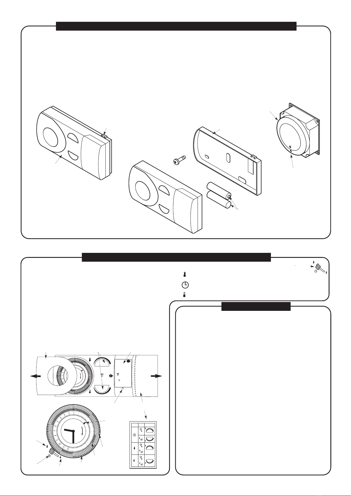
2. Remove the rear panel of the Programmable Room Thermostat Transmitter and, noting the polarity, fit the batteries (2 x1.5V L R6/AA) supplied. Press the Reset Button on the
Transmitter - the Transmitter will begin to communicate with the Receiver within 30 seconds. The Receiver will pick up a signal - this can be confirmed by switching on the
Transmitter to create a demand and observing the LED Indicator - see the section ‘ OPERATING MODE ’ below.
3. Secure the rear panel of the Transmitter to a suitable wall in the living room or hall. Refit the Transmitter in place on the rear panel.
OPERATING RANGE: Within a building - up to 20 metres. IMPORTANT: Avoid positioning large metallic objects, including mirrors, in the ‘line - of - sight’
between the Transmitter and Receiver as the communication between the two will be adversely affected.
NOTE: Boiler is IP20 when the receiver is fitted - this affects the positioning of the boiler in bath and shower rooms
Slot for Flat Bladed
Screwdriver
(twist slightly to release)
Batteries
Rear Panel
Programmable Room
Thermostat Transmitter LED Indicator
Receiver
FITTING THE PROGRAMMABLE ROOM THERMOSTAT TRANSMITTER
The Programmable Room Thermostat Transmitter has two temperature operating
levels, ‘Hi’ and ‘Lo’.
‘Hi’ Mode:This is set using the ‘Hi’ dial (5°C to 30°C) and will set the temperature to
the level desired when the property is occupied (e.g. 21°C).
‘Lo’ Mode:This is set using the ‘Lo’ dial (5°C to 15°C) and will set the temperature to
the level desired when the property is unoccupied or at night (e.g. 10°C).
To Set The Time: Slide the cover (A) off the unit. Rotate the timer clock clockwise
until the time is correct as indicated by the timer pointer.
To Set The ‘Hi’ & ‘Lo’ Central Heating Times: Move the tappets outwards for
‘Hi’ times and inwards for ‘Lo’ times. Each tappet = 15 minutes.
Summer: During the summer it is recommended that ‘Lo’ is selected using the 3
position switch.
Holiday Periods: When going on holiday set both dials to 5°C to provide frost
protection of the property.
13
14
15
16
17
18
19
20
21
22
23
24
9
6
3
12
LOW BATTERY
5°C 15°C
5°C 30°C
Hi
Lo
Lo
Hi
Hi
Lo
Operating Modes:
See rear of removable cover
To Set Time:
Rotate Outer Ring
To Adjust Temperature:
Rotate Small Dials
Low Battery:
If flashes yellow the
batteries need changing
Reset:
Press if in emergency
mode or immediately after
changing batteries
RESET
RESET
i
5117511 - Iss 3
A‘Hi’ & ‘Lo’ Room Temperature Dials Quick Reference Guide
13
14
15
16
17
18
19
20
21
22
23
24
9
6
3
12
Hi
Lo ‘Lo’ Position
‘Hi’ Position
Timer Pointer
Timed
between ‘Hi’
& ‘Lo’ ranges
‘Hi’
range
Rotate to
adjust time
Tappet
OPERATING MODE
Receiver
If the LED is Off then the Central Heating is Off.
If the LED is On then the Central Heating is On.
If the LED is continuously flashing once every 2 seconds then the batteries in the
Programmable Room Thermostat Transmitter are low & will soon require replacement.
If the LED is continuously flashing twice every second then the batteries in the
Programmable Room Thermostat Transmitter must be replaced immediately.
Programmable Room Thermostat Transmitter
If the LED is continuously flashing YELLOW once every 2 seconds then the batteries in
the Programmable Room Thermostat Transmitter are low & will soon require
replacement. If the LED is continuously flashing RED twice every second then the
batteries in the Programmable Room Thermostat Transmitter must be replaced
immediately.
Emergency Mode
If the receiver LED is continuously flashing 2 or 3 times a second then communication
between the Receiver & Transmitter has been lost. In this instance the Receiver enters
Emergency Mode. The Central Heating will operate for 3 minutes, followed by an Off period
of 9 minutes, then 3 minutes On again, repeating this sequence until the fault has been
rectified.
The unit will enter Emergency Mode when the following occurs:-
i) Communication between the Receiver & Transmitter is lost for over an hour.
ii) The batteries have become discharged.
NOTE: When Emergency Mode is activated Baxi Group cannot be held liable for any
excess consumption of gas.
Re-establishing Communication
The communication between the Receiver & Transmitter can be re-established at any time
by pressing the Reset button on the Transmitter. This must be done every time the batteries
are renewed.
NOTE: When any of the Room Thermostat settings have been changed they will normally
be communicated to the receiver unit on the boiler within 20 seconds, but may under certain
circumstances take up to 3 minutes.
SETTING THE PROGRAMMABLE ROOM THERMOSTAT
Hi
Lo
‘Lo’
range
= Temperature maintained at ‘Hi’ setting (irrespective of tappet position)
= Temperature alternates between ‘Hi’ & ‘Lo’ temperature periods
= Temperature maintained at ‘Lo’ setting (irrespective of tappet position)
To Set The Operating Mode: Slide the three position selector switch
to the desired position:-
5°C 30°C
Hi
5°C 15°C
Lo
Hi
Lo
Lo
Hi
Hi
Lo
Switch
Positi on
Tappet
Positi on
or
Temperature
Set Point
5°C 30°C
Hi
5°C 15°C
Lo
Hi
Lo
or
720113801
Operating Mode
label on rear face
Hi
Reset Button

Other Baxi Thermostat manuals

Baxi MAGO wifi User manual

Baxi

Baxi MAGO wifi User manual

Baxi RD-1200 User manual

Baxi

Baxi RD-1200 User manual

Baxi 5117391 Assembly Instructions

Baxi

Baxi 5117391 Assembly Instructions

Baxi 720644701 Assembly Instructions

Baxi

Baxi 720644701 Assembly Instructions

Baxi uSense 2 User manual

Baxi

Baxi uSense 2 User manual

Baxi TXW1AC Operating manual

Baxi

Baxi TXW1AC Operating manual

Baxi uSense User manual

Baxi

Baxi uSense User manual

Baxi uSense User manual

Baxi

Baxi uSense User manual

Baxi uSense User manual

Baxi

Baxi uSense User manual

Baxi 720030501 Manual

Baxi

Baxi 720030501 Manual

Baxi RD-1200 User manual

Baxi

Baxi RD-1200 User manual

Baxi Luna 3 Comfort User manual

Baxi

Baxi Luna 3 Comfort User manual

Baxi uSense User manual

Baxi

Baxi uSense User manual

Baxi uSense User manual

Baxi

Baxi uSense User manual

Popular Thermostat manuals by other brands

Pentair Nuheat Signature operating instructions

Pentair

Pentair Nuheat Signature operating instructions

Emerson White-Rodgers 70 Series Product overview

Emerson

Emerson White-Rodgers 70 Series Product overview

Danfoss BasicPlus2 WT-DM installation guide

Danfoss

Danfoss BasicPlus2 WT-DM installation guide

Carrier KSACN1001AAA owner's manual

Carrier

Carrier KSACN1001AAA owner's manual

Accolade BHT-1000 user guide

Accolade

Accolade BHT-1000 user guide

Grohe 34 123 quick start guide

Grohe

Grohe 34 123 quick start guide

Fujitsu AIRSTAGE Remo Set instruction manual

Fujitsu

Fujitsu AIRSTAGE Remo Set instruction manual

Honeywell PRO TH3110B installation guide

Honeywell

Honeywell PRO TH3110B installation guide

Siemens QMX2.P33 manual

Siemens

Siemens QMX2.P33 manual

Toptech T955WH operating manual

Toptech

Toptech T955WH operating manual

Honeywell FOCUSPRO TH6320R operating manual

Honeywell

Honeywell FOCUSPRO TH6320R operating manual

Stelpro B1T1 Series Installation

Stelpro

Stelpro B1T1 Series Installation

Ecobee ecobee4 install guide

Ecobee

Ecobee ecobee4 install guide

Salus VS35W installation manual

Salus

Salus VS35W installation manual

olympia electronics BS-830 manual

olympia electronics

olympia electronics BS-830 manual

Bosch BCC100 user guide

Bosch

Bosch BCC100 user guide

Alpha Smartech Plus instructions

Alpha

Alpha Smartech Plus instructions

Lennox X4146 installation instructions

Lennox

Lennox X4146 installation instructions

manuals.online logo
manuals.online logoBrands
  • About & Mission
  • Contact us
  • Privacy Policy
  • Terms and Conditions

Copyright 2025 Manuals.Online. All Rights Reserved.