Baxi 720030501 Manual

© Baxi Heating UK Ltd 2009
Please keep these instructions
in a safe place.
If you move house, please hand
them over to the next
occupier.
AUTO
PROG
INSTALLATION & OPERATING
INSTRUCTIONS
R.F. Digital Single Channel 7 Day
Programmable Room Thermostat
Transmitter & Receiver Kit
Part No. 720030501
Part No. 720030601
Part No. 720030701

2© Baxi Heating UK Ltd 2009
CONTENTS
1.0 Introduction 3
2.0 Locating the Transmitter 4
3.0 Fitting the Receiver 5
4.0 Transmitter Layout 6
5.0 Setting the Transmitter 7
6.0 Batteries & Specification 11
7.0 Communication Checks 12
Section Page

3
© Baxi Heating UK Ltd 2009
1.0 Introduction
1.1 Introduction
1.The kit consists of a Programmable
Room Thermostat Transmitter (Fig. 1) and
a Receiver Unit (Fig. 2) operated by radio
frequency, various fixings, 3 x AAA
batteries and a warning label.
2.TheTransmitter constantly monitors the
temperature of the room in which it is
installed. It can be operated in three
temperature modes,‘Lo’,‘Hi’ and ‘Frost
Protection’ or left in ‘Automatic’ to
operate as programmed.
3.TheTransmitter must be located as
described in the next section.
4.The Receiver can be fitted anywhere in
the property relative to the appliance as it
is wired directly to the appliance switched
live, providing good radio frequency
communication will be maintained.
AUTO
PROG
Room Thermostat
Transmitter
Receiver Unit
Fig. 1
Fig. 2

4© Baxi Heating UK Ltd 2009
2.0 Locating the Transmitter
2.1 Location
1.To ensure optimum operation of the
appliance and to achieve the desired
comfort levels the Programmable Room
Thermostat Transmitter must be correctly
located (Fig. 3):-
• In the main room of occupation
• Away from sources of
heat/light/draught
• On an internal wall at a height of
approx. 1500mm*
*Alternatively the Transmitter can be fitted
with the supplied plinth to allow free
standing on, for example, a sideboard or
shelf. It is recommended that the
Transmitter is operated free standing for a
period in several locations to determine the
best position.
2. It is important that no large metal objects
or mirrors are placed between the
Transmitter and Receiver, as they may
interfere with the Radio Frequency signal.
This could prevent the appliance working or
cause intermittent operation.
2.2 Fitting (Fig. 4)
1. Remove the cover by inserting a
screwdriver and twisting as shown.
2. Remove the batteries and insulating strip.
3. Select a suitable position for fitting and
mark the wall through the backplate, or fit
the free standing plinth (see above).
4. Once the optimum position has been
established drill & plug the wall (if wall
mounting). Secure the Transmitter with the
screws supplied and refit the batteries.
Replace the cover.
Min. 200 mm
1500 mm
AUTO
PROG
AUTO
PROG
PRO
Fig. 3
Fig. 4

5
© Baxi Heating UK Ltd 2009
3.0 Fitting the Receiver
3.1 Fitting the Receiver
1. Remove the cover by inserting a
screwdriver and twisting as shown (Fig. 5).
2. Select a suitable position for fitting and
mark the wall through the backplate.
3. Drill & plug the wall. Secure the
Transmitter with the screws provided.
Boiler Application (Fig. 6)
4. On the boiler remove the yellow link
wire from terminals 1 & 2 on the terminal
strip.
5. Connect the Receiver as shown in Fig. 6.
The Live & Neutral may be taken from the
boiler (as shown).
Baxi Ambiflo™ Heat Pump Application
(Fig. 7)
6. Connect the Receiver as shown in Fig. 7.
7. Use Controls Relay Board part no.
5132432 and read the instructions
supplied with it.
8. In both applications replace the
Receiver cover.
CAUTION: 230V ! Do not remove the
Receiver cover unless the
electrical supply is isolated !
b
br
bk
bk
g/y
1
N
L
2
230V
16A
Max.
Antenna
Button
L.E.D.
Cover
16A
Max.
Relay 1
Fuse 1A max.
(not supplied)
A1
A2
3A Switched
Fused Spur
Fig. 5
Fig. 6
Fig. 7

6© Baxi Heating UK Ltd 2009
4.0 Transmitter Layout
AUTO
PROG
Programming
Time Setting
Hi
Shutdown
Frost Protection
Lo
Selector Knob
Automatic ModeMulti-Function
Buttons
Programme Profile
‘Burner On’ Indicator
Current Day
(e.g.Wednesday)
Current Mode
(e.g. Hi)
Temperature
(Measured)
Current Time
Low Battery
Indicator
(only displayed
when battery low)

7
© Baxi Heating UK Ltd 2009
5.0 Setting the Transmitter
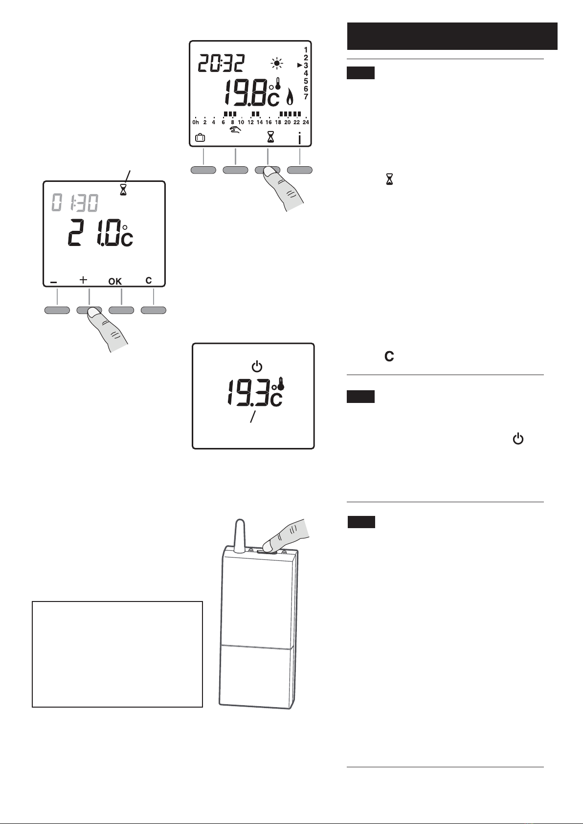
5.1 Setting the Time (Fig. 8)
1.Turn the Selector Knob to the ‘Time
Setting’ position.The day identification
numbers (1 - 7) will flash.
2. Press ‘+’ or ‘-’ to select the required day,
1 = Monday, 2 = Tuesday etc.
3. Press ‘OK’ to confirm the setting.The
‘hour’ will start flashing. Press ‘+’ or ‘-’ to
select the required hour (e.g. 18), and
press ‘OK’ to confirm.
4.When the ‘minute’ starts flashing repeat
the process to set the ‘minutes’ for the
current time.
5.Turn the knob to exit the setting mode.
5.2 Setting the Temperature
Set Points (Figs. 9, 10 & 11)
1.To set the ‘Frost Protection’ temperature
turn the Selector Knob to the position.
7°C is the default setting. Press ‘+’ or ‘-’ to
change the setting between 5°C & 15°C.
2. To set the ‘Lo’ temperature turn the
Selector Knob to the position. 15°C is
the default setting. Press ‘+’ or ‘-’ to change
the setting between 10°C & 30°C.
(N.B. for Ambiflo™ applications do not set
below 14°C).This is the temperature that
will be maintained during the periods of
the day when there is no Central Heating
programme.
3. To set the ‘Hi’ temperature turn the
Selector Knob to the position. 19°C is
the default setting. Press ‘+’ or ‘-’ to change
the setting between 10°C & 30°C. (N.B.
for Ambiflo™ applications do not set
below 14°C).This is the temperature that
will be maintained during the periods of
the day when the Central Heating is
programmed to be ‘ON’ (see below).
4.Turn the knob to exit the setting mode.
Day
Hours
Minutes
AUTO
PROG
AUTO
PROG
AUTO
PROG
AUTO
PROG
Fig. 8
Fig. 9
Fig. 10
Fig. 11

8© Baxi Heating UK Ltd 2009
5.0 Setting the Transmitter
5.3 Programming (Fig. 12)
1.The default programme is ‘Hi’ mode. set
for operation from 06:00 A.M. to 11:00
P.M. each day of the week.
2.To change the programme turn the
Selector Knob to the position.
3.The first ‘time slot’ will flash off & on.
4. Choose or for each hour, or press
to go to next change in programme.
Press to select Lo mode for the hour or
for Hi mode.
Once done press ‘OK’ for next day, or:-
Quick Programming.
To apply the same programme to the
following day press and hold ‘OK’ for 3
seconds until the programme for the
following day is displayed.
5.Turn the knob to exit the setting mode.
5.4 Automatic Mode (Fig. 13)
1.Turn the Selector Knob to the
position.
2.When starting, the temperature
measured by the Transmitter is displayed
with the symbol above the ‘°C’. Press ‘ ‘
for 3 seconds to display the set-point
temperature.
3. It is not necessary to operate the set
programme. If required one of the
‘continuous’ modes can be selected.
Turn the Selector Knob to:-
for continuous Lo
for continuous Hi
for continuous Frost Protection
PROG
Lo mode
for 1 hour
for 1 hour
Go to the next
program change
Confirm and go to
the next day
1st time
slot
Time slot
consulted Day
Program
profile
Hi mode
AUTO
PROG
AUTO
Holiday
mode
Switches current mode,
e.g. Hi to Lo,
or vice versa
Manual temperature mode
(from 30 minutes to 72 hours)
Time
Current setting
(e.g. Hi)
Day (e.g. Tuesday)
Burner On
indicator
Measured
temperature
Fig. 12
Fig. 13

5.0 Setting the Transmitter
5.5 Holiday Mode (Figs. 14 & 15)
In this mode a temperature from 5°C to
15°C can be set to be maintained for a
period from 1 to 365 days.
1.Turn the Selector Knob to the
position.
2. Press and the number of days will
flash off and on. Press ‘+’ or ‘-’ to set the
number of days:-
For example, if leaving on July 10th and
returning on July 19th select 9 days.
Automatic Mode will restart at 00:00h
on July 19th.
3. Press ‘OK’ to confirm.The temperature
will flash off and on. Press ‘+’ or ‘-’ to set
the temperature. Press ‘OK’ to confirm.
4. Press or turn the Selector Knob to
cancel the ‘Holiday’ mode, when returning
earlier than expected for example.
5.6 Manual Mode (Fig. 16)
Manual Override until the next Change
in Programme (can only be activated
when in Automatic mode)
1.This mode can be used to alternate
between ‘Hi’ and ‘Lo’ modes until the next
programme change.
2. Press to operate.The symbol will
appear on the display and the mode will
change.
For example, if the Central Heating
programme is ‘ON’ (‘Hi’) it will be
switched to ‘Lo’ for the remainder of
the timed programme. During this time
‘Hi’ can be reverted to by pressing
again.
9
AUTO
Manual mode
is the current mode
Fig. 14
Fig. 15
Fig. 16

10 © Baxi Heating UK Ltd 2009
5.0 Setting the Transmitter
5.7 Manual Override for a period of
between 30 minutes & 72 hours
(Figs. 17 & 18)
1.This mode can be used to set either the
‘Hi’ or Lo’ mode for a set period of time,
and will override any set programme.
2. Press to operate.The time for the
Manual Mode flashes, with the
temperature to be maintained also
displayed.
3. Press ‘+’ or ‘-’ to set the required time
by 30 minute increments. Press ‘OK’to
confirm and then press ‘+’ or ‘-’ to set the
required temperature. Press ‘OK’.The
manual time and temperature that have
been chosen will continue to be displayed.
4. Press to cancel the Manual Mode.
5.8 Shutdown Mode (Fig. 19)
1.To shut down the heating, in summer for
example, turn the Selector Knob to .
2.The measured temperature will
continue to be displayed.
5.9 Emergency Mode (Fig. 20)
1. If communication is lost between the
Transmitter and Receiver for longer than 1
hour the unit will go into continuous
heating mode to ensure that the property
will not be without heating.
2.This will continue until communication is
re-established (see Section 7.2).
3.When in this mode the heating can be
turned OFF & ON if required by operating
the button on the Receiver:-
Heating ON = Receiver LED ON
Heating OFF = Receiver LED OFF
Manual mode
is the current mode
Measured
temperature
Fig. 17
Fig. 18
Fig. 19
Fig. 20
NOTE: If the property is to be left
unoccupied for a significant length
of time it is recommended that the
Transmitter batteries are replaced.
Baxi Group is not liable for any
additional fuel costs incurred whilst
in Emergency Mode.

11
© Baxi Heating UK Ltd 2009
6.0 Batteries & Specification
6.1 Low Battery (Fig. 21)
1.When the Battery Level symbol is
displayed the batteries should be changed
within 3 months.This symbol will appear
ONLY when the batteries are low.
6.2 Transmitter Specification
• Batteries:- 2 x LR03 or AAA 1.5V
• Class III insulation
• 868 MHz transmission frequency
• IP 30 Protection
• Operation temperature 0°C to +40°C
6.3 Receiver Specification
• 240V ac 50 Hz (+/- 10 %) power supply
• Class II insulation
• 868 MHz transmission frequency
• IP 44 - IK 04 Protection
• Operation temperature -5°C to +50°C
Battery level
symbol
Fig. 21

© Baxi Heating UK Ltd 2009
All descriptions and illustrations provided in this leaflet have been carefully
prepared but we reserve the right to make changes and improvements in
our products which may affect the accuracy of the information contained in
this leaflet. All goods are sold subject to our standard Conditions of Sale
which are available on request.
BAXI
A Trading Division of Baxi Heating UK Ltd (3879156)
A Division of Baxi Group
Brooks House, Coventry Road, Warwick. CV34 4LL
Technical Enquiries 0844 871 1555
Website www.baxi.co.uk
e&oe
Comp No720124602 - (1/10)
7.0 Communication Checks
7.1 Test Mode (Fig. 22)
1.Turn the Selector Knob to the
‘Shutdown’ position and press the right
hand Adjustment Button for 5 seconds
until CF06’ and ‘CnF’ are displayed.
2. Press ‘OK’.‘CF07’ and ‘tESt’ will be
displayed. A signal is sent from the
Transmitter to the Receiver every 3
seconds.The ‘X2D’ symbol will be be
displayed briefly.
NOTE:The Receiver LED will flash
every time a data signal is received.
3.To cancel this mode turn the Selector
Knob.
7.2 Re-establishing Communication
(Fig. 23)
1.Turn the Selector Knob to the
‘Shutdown’ position and press the right
hand Adjustment Button for 5 seconds.
until CF06’ and ‘CnF’ are displayed.
2. Press the Button on the Receiver until
the L.E.D. flashes, and press ‘+’ on the
transmitter.The Transmitter will send a
signal to the Receiver.The ‘X2D’ symbol
will be be displayed briefly.
3. Check that the L.E.D. on the Receiver is
no longer flashing.The Receiver and
Transmitter are now linked.To test, follow
Section 7.1 above.
4.To cancel this mode turn the Selector
Knob.
7.3 Default Settings (Fig. 24)
1.To return to initial default temperature
settings:-
• Turn Selector Knob to ‘Shutdown’
• Press left hand button for more than
10 seconds
• ‘init’ will be displayed
• Press ‘OK’ to confirm or ‘C’ to cancel
Button
L.E.D.
AUTO
PROG
10 sec.
Fig. 22
Fig. 23
Fig. 24
This manual suits for next models
2
Table of contents
Other Baxi Thermostat manuals