Invisible systems QCO168 User manual

Installation Manual
Ultra RF Analogue Transmitter
QC0168
Manual Ref: QC0168
Version: March 17 1.0

Ultra RF Analogue Transmitter Manual
InvisibleSystemsLimited Page|2
7‐9BeethamRoad,MilnthorpeCumbria,LA77QL,England
Phone:01539722520Email:info@invisible‐systems.com
System Concept
Version
Tracking
DateAuthorChanges
v1.014/03/2017ChrisBoddy
RFTransmittersconnecttosensorsormetersandsenddatatotheinfrastructure
internetconnectedGatewayonsite
TheGatewaystoresandtransfersthedatatotheRealtimeOnlinecloudserverovera
securemobilecellularconnection
RealtimeOnlineprovidesawebbasedportalofvisualisationdashboards,reports,
graphsandtransmitsouttailoredautomaticreportsandnotificationsintheeventof
exceptions

Ultra RF Analogue Transmitter Manual
InvisibleSystemsLimited Page|3
7‐9BeethamRoad,MilnthorpeCumbria,LA77QL,England
Phone:01539722520Email:info@invisible‐systems.com
Contents
1.
Introduction............................................................................................................................4
2.
Installation..............................................................................................................................5
2.1
FittingExample.......................................................................................................................5
3.
Testingthecircuit...................................................................................................................7
4.SensorNumbering...................................................................................................................8
5.LocatingSensors......................................................................................................................8
4.
Checkingoperation...............................................................................................................10
5.
Dashboardconfiguration.......................................................................................................12
6.
Appendix1–PartNumbers...................................................................................................13

Ultra RF Analogue Transmitter Manual
InvisibleSystemsLimited Page|4
7‐9BeethamRoad,MilnthorpeCumbria,LA77QL,England
Phone:01539722520Email:info@invisible‐systems.com
1. Introduction
TheAnaloguetransmitterdefinedinthisspecificationisdesignedtomeasurethemAoutput
beinggeneratedbythecompatiblechosenequipmentformonitoring.
Forexample,therearenumerousanaloguedevicesusedintheHVACcontrolsworld.Typically,
analogueoutputdevicesareusedtoprovidemodulatingcontrolofvalves,dampers,electric
motorsthroughvariablespeeddrivesandawidevarietyofotherdevices.Themostcommon
devicesassociatedwithanalogueoutputsaresequencers,variablespeeddrives,silicon
controlledrectifiersandactuators.Afterconnectionoftheanaloguetransmitterinserieswith
thesecircuitstheoperationalstatuscanbemonitored.
Commonlytheanaloguetransmitterisusedtomonitoramps,pressure,waterflow,leveltanks,
andPhvalueswhenattachedtotheappropriateequipmentsupplyingaanalogueoutput.
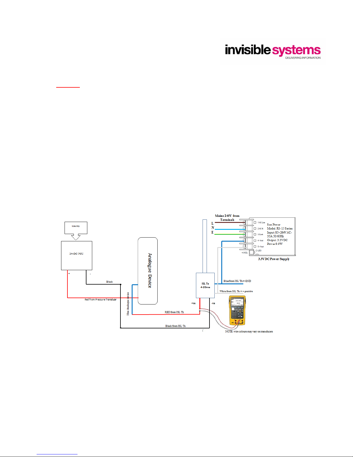
Therearedifferenceswithequipmentprovidingananalogueoutput,somedeviceshavean
outputwithaactivevoltagewherethistransmittercanbedirectlyconnectedandothershavea
analogueoutputthatneedsexcitingwithapowersupply.Ifthisisthecasetheappropriate
powersupplywouldneedtobeconnectedinadditiontotheanaloguetransmittertoallow
operation.
Theanaloguetransmitterisavailableinfourdifferentconfigurations,forcompatibilityto
differentapplicationsandequipment:‐
4‐20mA(3999‐913‐2095)
0‐1volt(3999‐913‐2110)
0‐5volt(3999‐913‐2111)
0‐10volt(3999‐913‐2112)
Features
Avarietyofavailableradiofrequencyoptions
Smallfootprint
Automaticdatacollectionandtransmission
Wireless,rangeofupto15kmlineofsight
Batterypoweredwithupto3yearbatterylife
Technicalinformation
Operatingfrequency868MHz(Otherfrequenciesavailable915MHz)
Operatingrangeupto15kmlineofsight
Suitabletomonitoranydevicewithaanalogueoutput
StorageConditions:0°Cto+50°C
RelativeHumidity:25%to95%
OperatingTemperature:0°Cto40°C
Applications,anycompatiblemeter/devicewithaanalogueoutputi.e.:‐
Flowmonitoring
PHvaluemonitoring
TankLevelMonitoring

Ultra RF Analogue Transmitter Manual
InvisibleSystemsLimited Page|5
7‐9BeethamRoad,MilnthorpeCumbria,LA77QL,England
Phone:01539722520Email:info@invisible‐systems.com
2. Installation.
Theconnectionfortheanaloguetransmitterisasfollows;
(Mustalwaysbeconnectedtotheappropriateenergisedanaloguecircuit)
Redcable+
Blackcable‐
Theseconnectionsneedtobeconnectedinserieswiththeappropriatecircuitastheyworkon
thesameprincipleasanampmeter.Seeexamplecircuitdiagramsbelowformoreinformation.
2.1 FittingExample
Most Realtime-Online™ sensors have a unique mounting clip on the battery
compartment which allows the sensor to be installed:
Mounted with screws through the mounting clip.
“Careshouldbetakenwhenmountinganddrillingholesinthe
designatedareaasthecablespresentontheinsideofenclosureswill
needtobeavoided”

Ultra RF Analogue Transmitter Manual
InvisibleSystemsLimited Page|6
7‐9BeethamRoad,MilnthorpeCumbria,LA77QL,England
Phone:01539722520Email:info@invisible‐systems.com
Belowshowsexamplesofdifferentcircuitdiagramswiththe4‐20mAtransmitterfittedinseries
(currentloop)withintheappropriatecircuit.Theothertransmitterstypesreferredtointhis
manualarewiredinthesameway;the4‐20mAisshownasanexample.
Diagram1
Diagram2
Diagram3

Ultra RF Analogue Transmitter Manual
InvisibleSystemsLimited Page|7
7‐9BeethamRoad,MilnthorpeCumbria,LA77QL,England
Phone:01539722520Email:info@invisible‐systems.com
Caution
“Whenconnectingtothistypeofsolution,thecorrectsafetyprotocolsforsite
wouldneedtobefollowedwhenworkingonthistypeofequipment.Itis
recommendedthattheassociatedmanualfortheequipmentbeingconnectedto
befimiliarisedwithpriortocommencementofwork.”
3. Testingthecircuit.
AnappropriatemAmeterisrequiredtoenabletestingofthecircuit.
AswiththetransmitterconnectionthemAmeterisrequiredtobefittedwithinthecircuitin
seriesbeforethetransmitterconnection.
Belowshowsdiagram3withaMultimeterconnectedinseries.Thisallowsfortheanalogue
rangebeingdeliveredbythedevicetobecrosscheckedwiththemeter.

Ultra RF Analogue Transmitter Manual
InvisibleSystemsLimited Page|8
7‐9BeethamRoad,MilnthorpeCumbria,LA77QL,England
Phone:01539722520Email:info@invisible‐systems.com
4.SensorNumbering
Eachsensorissuppliedwithauniqueserialnumbermarkedonthesidetogetherwithabarcode
whichisusedtoidentifythesensorontheRealtime‐Onlinedashboard.
Itisvitalthesenumbersareaccuratelyrecordedotherwiseitwillbeimpossibletoidentifythe
sensorinISLSetuportheserverdashboardforthespecificsite.
Note:‐ asensornumbercannotappearmorethanonceonthesamesite,butcanappearon
morethanonesitedashboard.
5.LocatingSensors
Realtime‐Online™Sensorsuseradiofrequencycommunicationtoalocalgateway.Thedistance
betweensensorsandthegatewaycanalsobeverylong(upto15Kmlineofsight).However,
environmentalfactorssuchaswallsandfurniturecanreducethisdistanceconsiderablyso
optimalplacementofsensorsisimportant.
Note;thisdocumentdoesnotspecificallycovertheinstallationofGatewayswhicharecoveredin
aseparatedocument,(seeindex)butthefollowinggeneralguidanceisgiven.
Whenplacingsensors,avoidthefollowing:
a. Placingthetransmitterinmetalenclosuressuchasadistributionboards.
b. Thetransmittersaresplashproofandaresuitableforinstallationinoutdoorareas,butare
not100%waterproof.Donotinstalltheminpositionswheretheyareliabletobe
submerged.
c. DonotinstallthetransmittersclosetootherRFsourcessuchasalarmsystems,door
openersorotherradiosystems.AlthoughtheamountofRFenergytransmittedbythe
sensorsisverysmallindeed,thereisapossibilitythattheycouldinterferewithother
electricaldevices,sotheymustnotbeinstalledclosetootherdeviceswhichcouldbe
affectede.g.medicaldevicesorwirelessalarmsystems.
Whensittingthegateway,trytoensurethelocationisapproximatelyequidistantinradiosignal
termsfromallthesensors.
Typically,sensorscanbeexpectedtopassthrough4–5normalinternalwallswithoutdifficulty.

Ultra RF Analogue Transmitter Manual
InvisibleSystemsLimited Page|9
7‐9BeethamRoad,MilnthorpeCumbria,LA77QL,England
Phone:01539722520Email:info@invisible‐systems.com
Thefollowingillustrationshowshowsensorswhicharehiddenbehindlargemetalobjectsliketanks
orsteelwallsmayhavedifficultyintransmittingtothegateway.
Notes
Caremustbetakenwheninstallingthissensorasliveelectricalcircuitsareusuallywithin
thevicinity.Seektoguidanceofaqualifiedelectricianifyouareunsure.
Battery
Forsafetyconsiderations,allwirelesstransmittersaretransportedwiththeinternalbattery
disconnected.Usuallythiscanbeconfirmedifthewhiteconnectorispassingthroughthebase.
Onfirstuseitisthereforenecessarytoconnectthebatteryfollowingthestepsbelow:
1.Removethefourscrewsatthebaseofthesensor.
Thenremovethebaseandthesealinggasket.
2.CarefullyinsertthesmallwhiteplugintothePCBsocketandensurethecablepasses
throughthenotchtoavoidpinching.Seediagrambelow.
3.Replacethesealinggasket,coverand4screws.DONOTOVERTIGHTEN!
Possible
repeater
location

Ultra RF Analogue Transmitter Manual
InvisibleSystemsLimited Page|10
7‐9BeethamRoad,MilnthorpeCumbria,LA77QL,England
Phone:01539722520Email:info@invisible‐systems.com
4. Checkingoperation
FollowinginstallationofthePulsetransmitter,itissuggestedthattheoperationischeckedto
ensurethetransmitterisbeingreceivedbytheGateway.
OpenUltraRFGatewaySetup–Thisshouldbelocatedonthedesktopofyour
laptop.
Onfirstuse,ifrequested,selectthe
USBleadbeingusedandhighlight
foruse.
Screeninformationbeingdisplayed.
TheScreenwillshowthetransmittersitcanseeinrangeofthereceiver;thesecanbesortedby
sensortypeorIDasperpreference.
Nameleadconnection
andselectitindrop
downlist

Ultra RF Analogue Transmitter Manual
InvisibleSystemsLimited Page|11
7‐9BeethamRoad,MilnthorpeCumbria,LA77QL,England
Phone:01539722520Email:info@invisible‐systems.com
EachTransmitterwillshowthefollowing
1. SensorID
2. TransmitterType
3. BatteryVoltage
4. Valuesbeingreceived
5. SignalStrengthandfrequency
Itisimportanttocheckallofthisinformationtoconfirmthateachsensorisbeingseenbythe
gatewayandatregularintervalsinrelationto(5).Bluecolourdotsshowdirectmessagesbeing
receivedandOrangecolourdotsshowmessagesreceivedviarepeaters.
CorrectsetupandoperationofRealtime‐online,willrequirealltheSensorID’sandTransmitter
typesinconjunctionwiththeGatewayID.
TheRSSIisshownindBmwithabarchartshowingsignalstrength.Thisisanimportant
parameter.ThetablebelowshowsdBmrangesinrelationtoSignalstrength.
Therangeshownabovereads‐100dBmthisisshowninthetableasaMarginalsignaltherefore
willneedimprovingeitherbyreviewingthetransmitterlocation,movingtheGatewaycloseror
addingasignalrepeaterinbetweentransmitterandreceiver.
ValueRSSI
dBm
Signal
Strength
ValueRSSI
dBm
Signal
Strength
2 ‐109Marginal17 ‐79Good
3 ‐107Marginal18 ‐77Good
4 ‐105Marginal19 ‐75Good
5 ‐103Marginal20 ‐73Excellent
6 ‐101Marginal21 ‐71Excellent
7 ‐99Marginal22 ‐69Excellent
8 ‐97Marginal23 ‐67Excellent
9 ‐95Marginal24 ‐65Excellent
10 ‐93OK25 ‐63Excellent
11 ‐91OK26 ‐61Excellent
12 ‐89OK27 ‐59Excellent
13 ‐87OK28 ‐57Excellent
14 ‐85OK29 ‐55Excellent
15 ‐83Good30 ‐53Excellent
16 ‐81Good
Furthertechnicalreferenceandproductinfocanbeobtainedfromassociateddatasheets

Ultra RF Analogue Transmitter Manual
InvisibleSystemsLimited Page|12
7‐9BeethamRoad,MilnthorpeCumbria,LA77QL,England
Phone:01539722520Email:info@invisible‐systems.com
5. Dashboardconfiguration
FollowingsuccessfullogintoRealtime‐Online™withyourusernameandpassword,createnew
sensor(System>SensorSetup>CreateNewSensor)
EnterSensorIDnumberlocatedonthesideoftheStatusTransmitter
NametheSenorasrequiredwithreferencetositerequirementsforeaseofidentification.
SelectSensorType=‘Condition’.
Selectunit=asdesiredindropdownmenu.
Select‘Analog’fromdropdown.
Fillintheanalogueformulathatrelatestothe4‐20mascalingforthedevicebeingmonitored.
Belowshows*1,thissettingwithonlyshowtheactualmAreadingbeingseenatthe
transmitterconnection.
Ifalertsareneededthedelaybeforealarmcanbeset.
ThealertDay/NightOptioncanbeswitchedonoroffbyselectingtheoption.
Click‘CreateSensor’
Example:
DualInputStatusTransmitter
WhenusingadualinputstatustransmitterrepeatthesetupasabovebutchangetheLoop1
inputtoLoop2.
Thenupdatesensor.

Ultra RF Analogue Transmitter Manual
InvisibleSystemsLimited Page|13
7‐9BeethamRoad,MilnthorpeCumbria,LA77QL,England
Phone:01539722520Email:info@invisible‐systems.com
6. Appendix1–PartNumbers.
PartNumberItemDescription
3999‐913‐2095UltraRFAnalogueTransmitter4‐20mAInput
3999‐913‐2110UltraRFAnalogueTransmitter0‐1Volt
3999‐913‐2111UltraRFAnalogueTransmitter0‐5Volt
3999‐913‐2112UltraRFAnalogueTransmitter0‐10Volt
Table of contents
Other Invisible systems Transmitter manuals