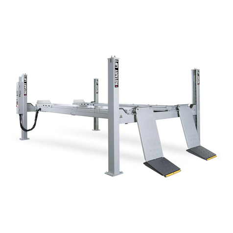
Rotary VLXS7 User manual
Other Rotary Lifting System manuals

Rotary
Rotary 1000 SERIES Manual
Rotary
Rotary SPO54M User manual

Rotary
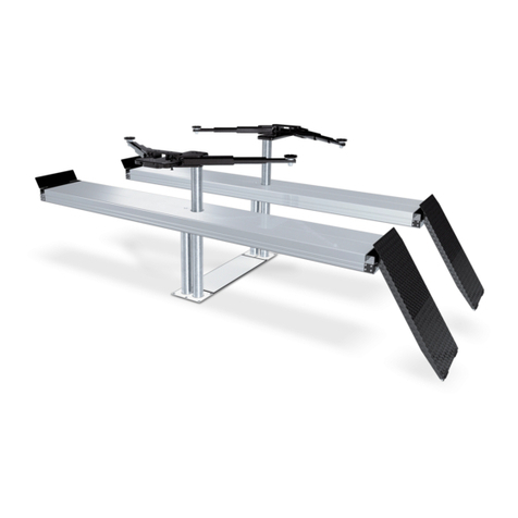
Rotary SPO16 User manual
Rotary
Rotary SL235MP User manual
Rotary
Rotary GEMINI 25-30-35 User manual
Rotary
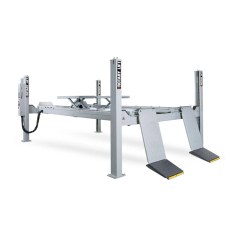
Rotary SM65-51 User manual
Rotary
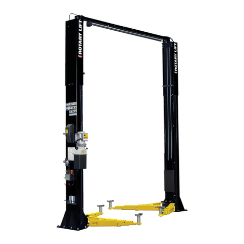
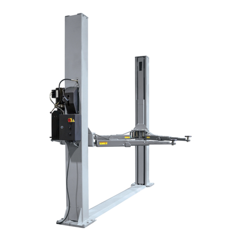
Rotary SPO12 Standard 500 Series Manual
Rotary
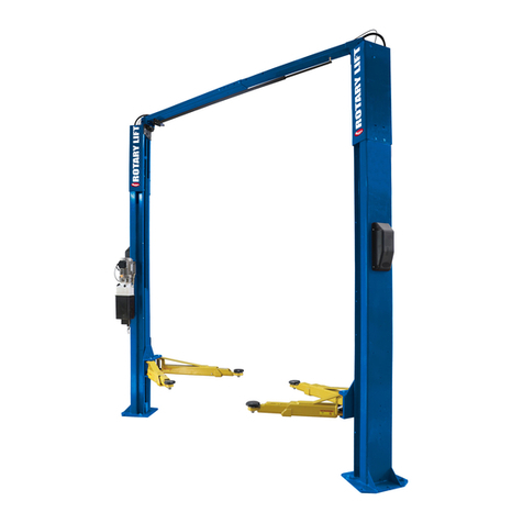
Rotary SGL35M User manual
Rotary
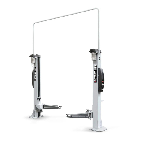
Rotary SPOA10NB Series User manual
Rotary
Rotary SPM40 Manual

Rotary
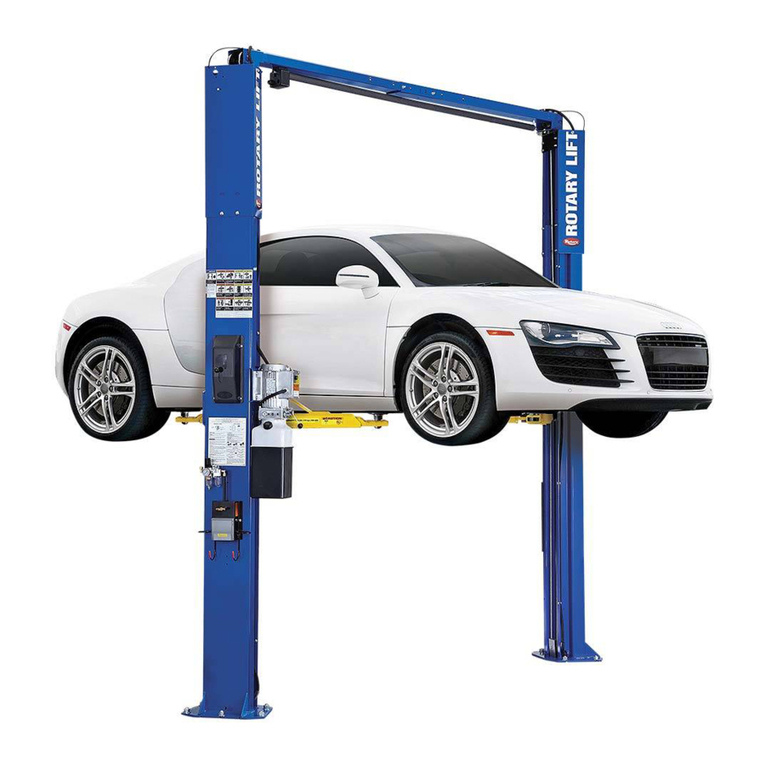
Rotary GLP 35 User manual
Rotary
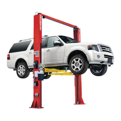
Rotary SPOA7 Series Manual
Rotary
Rotary SPO12 Standard User manual
Rotary
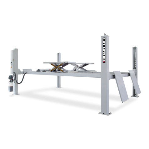
Rotary 2000 Series User manual
Rotary
Rotary AR43-5MB Operating instructions
Rotary
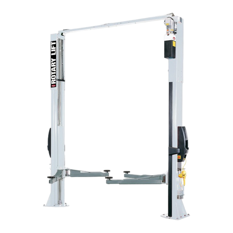
Rotary 600 Series Manual
Rotary
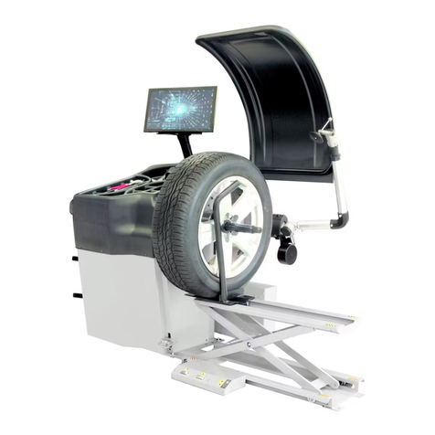
Rotary SPO55E Manual
Rotary
Rotary GAR324 User manual
Rotary
Rotary MASTER GEAR MGE 2.0 Manual
Rotary
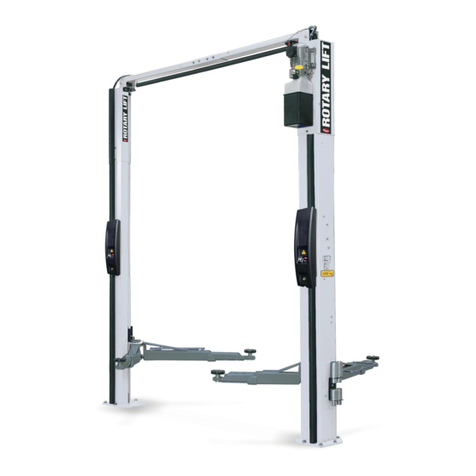
Rotary SPOA3TE 600 Series User manual
Popular Lifting System manuals by other brands

morse
morse 82H-124 Operator's manual

Braun
Braun NL955 Series Operator's manual

haacon
haacon 1889.10 quick start guide

Protekt
Protekt AT 252 instruction manual

R. Beck Maschinenbau
R. Beck Maschinenbau HS 600 operating manual

Nova Technology International, LLC
Nova Technology International, LLC NAS Series quick start guide

Genie
Genie Z-60/34 Operator's manual

Screen Technics
Screen Technics INTERFIT Vertical Up Lift instructions

Mortuary Lift
Mortuary Lift ULTIMATE 1000 instructions

Custom Equipment
Custom Equipment Hy-Brid 3 Series MAINTENANCE & TROUBLESHOOTING MANUAL

Custom Equipment
Custom Equipment Hy-Brid Lifts 2 Series Maintenance and troubleshooting manual

Hy-Brid Lifts
Hy-Brid Lifts HB-P3.6 MAINTENANCE & TROUBLESHOOTING MANUAL

BERG
BERG BeNomic EasyLeaf Technical manual

Powermate
Powermate LiftGate LG-3 Installation & operation manual

Snorkel
Snorkel TM12 Series Operator's manual

Terberg
Terberg OMNIDEKA Translation of the original instructions

Harmar Mobility
Harmar Mobility AL625 Installation & owner's manual
Ricon
Ricon Mirage F9T Service manual

