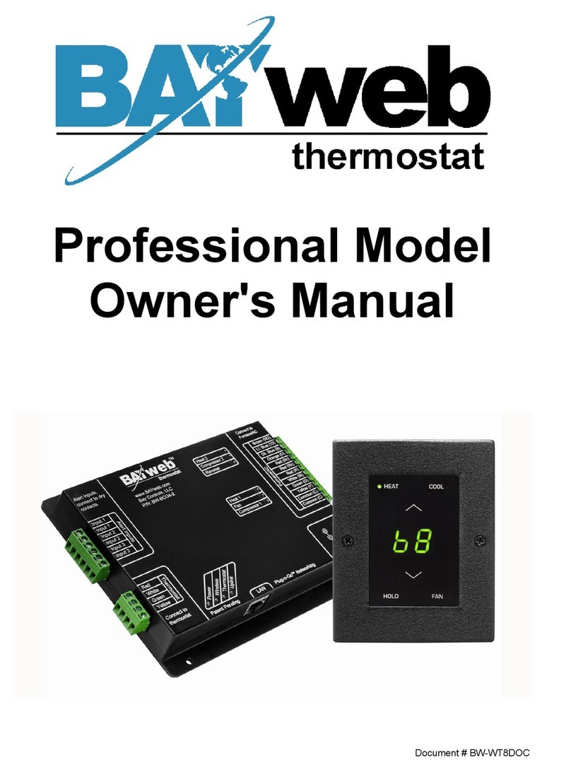
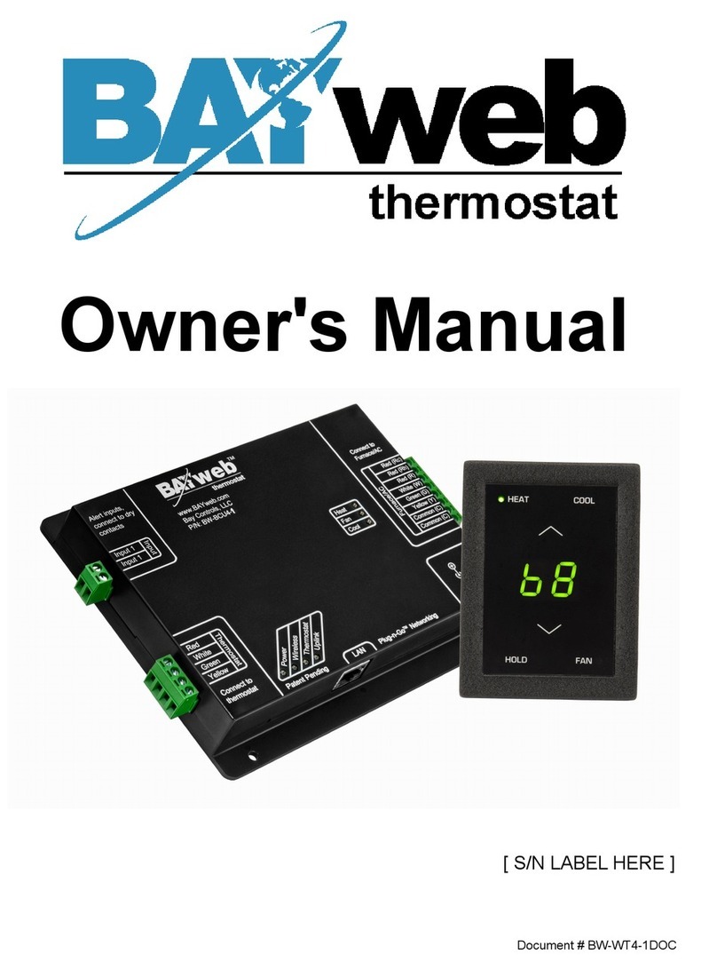
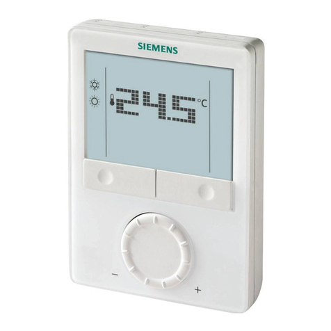
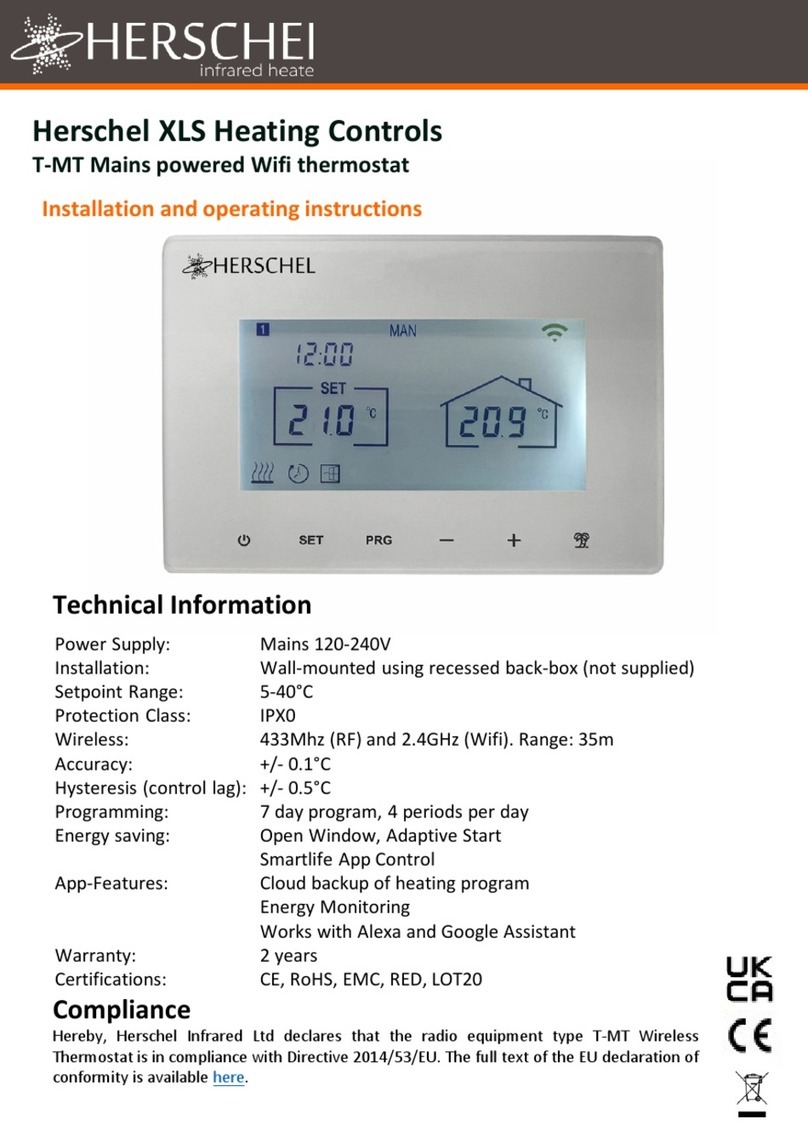
BAYweb BW-WT2 User manual

Advanced Model
Owner's Manual
Document # BW-WT4-2DOC

BAYweb Thermostat Model BW-WT2 Owner's Manual
Cop right © 2009-2011 Ba Controls, LLC
Revision: 1.7 October 6, 2011
BAYweb is a registered trademark of Ba Controls, LLC.
Patent pending technologies are used in the BAYweb Thermostat.

Table of Contents
Introduction.............................................................................................................1
About This Manual..................................................................................................1
Safet Precautions..............................................................................................1
Limited Warrant .................................................................................................3
Limitation on Liabilit ..........................................................................................3
Unauthorized Repair...........................................................................................3
Installation...............................................................................................................4
Overview.............................................................................................................4
Identif Wiring.....................................................................................................6
Install Control Module.........................................................................................8
Install Thermostat Ke pad................................................................................10
Connect to the Internet.....................................................................................11
Configure the Thermostat.................................................................................12
Test Operation..................................................................................................13
Operation..............................................................................................................14
Using the Thermostat Ke pad..........................................................................14
Using the Web Site...........................................................................................14
Using Your Mobile Phone.................................................................................15
Occupanc Sensing..........................................................................................15
Implementing Occupanc Sensing...............................................................15
Testing Occupanc Sensing.........................................................................16
Occupanc Sensing with Multiple Thermostats...........................................16
Alerting..............................................................................................................17
Implementing Alerting...................................................................................17
Testing Alerting.............................................................................................17
Reference..............................................................................................................18
Thermostat Ke pad..........................................................................................18
Error Codes..................................................................................................18
Control Module.................................................................................................19
Alert Inputs...................................................................................................19
Thermostat Connector..................................................................................20
Furnace/AC Connector.................................................................................20
LAN Port.......................................................................................................20
Power Suppl ...............................................................................................20
Status Indicators...........................................................................................20
Troubleshooting................................................................................................21
Solutions to Problems..................................................................................22
Obtaining Support........................................................................................26
Optional Outputs...............................................................................................26
Humidifier Control.........................................................................................26
Damper Control............................................................................................26
Thermostat Connections..................................................................................26
Thermostat Wiring............................................................................................27
Specifications........................................................................................................28

Introduction
Thank ou for purchasing the BAYweb Thermostat. You now have one of the most advanced
Heating, Ventilating, and Air Conditioning (HVAC) control s stems available toda .
This thermostat is easil installed b home owners or HVAC professionals. It can be used to
replace an existing thermostat or for installation with new heating or cooling equipment.
This model of the BAYweb Thermostat (BW-WT2) is designed for use with conventional or
heat pump based s stems that use single or multistage stage control.
About This Manual
This manual contains the information necessar for installing and operating the BAYweb
Thermostat. However, since installations ma var , these instructions ma not cover all details
or variations in the equipment supplied or ever question that ma possibl arise during use.
If a question or situation develops which is not answered directl in this manual, contact
BAYweb support for specific answers and advice.
You should become familiar with the contents of this manual before the thermostat is put into
service. This is particularl important with regard to the safet precautions listed in the
Introduction section, and those included at relevant points in other sections of this manual.
Note that this manual is is updated periodicall . You can download the latest version at
www.ba web.com.
CAUTION: Read, be sure to clearl understand, and then carefull follow all of the
directions and procedures included in this manual. Failure to adhere to the
guidelines and specific instructions provided could cause equipment damage and
serious personal injur or death.
Safety Precautions
Low voltage thermostats, including the BAYweb Thermostat, use 24 VAC control signals
limited to 3.2 amperes to interface to our furnace and air conditioning equipment. These low
voltage control signals do not normall represent an electric shock hazard unless used in an
environment for which the equipment was not designed for, such as a wet location.
1
!

Ba Controls, LLC. expressl disclaims responsibilit or liabilit for an injur or damage
caused b failure to observe specified or other common safet precautions or failure to
exercise ordinar caution, common sense, and due care required in installing and operating
the thermostat even though not specified herein.
The alert message shown here appears throughout this manual to indicate those situations
and times when special care is necessar to prevent equipment damage or personal injur .
CAUTION: This indicates that there could be the possibilit of equipment damage
or personal injur .
CAUTION: If this equipment is used in a manner not specified b Ba Controls,
LLC., there ma be a risk of equipment damage, serious personal injur , or death.
2
!
!

Limited Warranty
Subject to the limitations contained below, and except as otherwise expressl provided
herein, Seller warrants to the Bu er that all tangible articles supplied b Seller or services
provided b Seller will be free of defects in materials or workmanship under normal use and
care until the expiration of the applicable warrant period. Goods are warranted for five (5)
ears from the date of purchase. If Bu er discovers an defects and notifies Seller thereof in
writing during the applicable warrant period, Seller shall at its option promptl correct, repair,
or replace F.O.B. point of manufacture that portion of the good found b Seller to be defective,
or refund the purchase price of the defective portion of the goods/services. All replacements
or repairs necessitated b inadequate maintenance, normal wear and usage, unsuitable
power sources, unsuitable environmental conditions, accident, misuse, improper installation,
modification, repair, storage or handling, or an other cause not the fault of Seller are not
covered b this limited warrant , and shall be at Bu er’s expense. Seller shall not be obligated
to pa an costs or charges incurred b Bu er except as ma be agreed upon in writing in
advance b an authorized Seller representative. Goods repaired and parts replaced during
the warrant period shall be in warrant for the remainder of the original warrant period or
ninet (90) da s, whichever is longer.
THERE ARE NO REPRESENTATIONS OR WARRANTIES OF ANY KIND, EXPRESS OR
IMPLIED, AS TO MERCHANTABILITY, FITNESS FOR PARTICULAR PURPOSE, OR ANY
OTHER MATTER WITH RESPECT TO ANY GOODS OR SERVICES.
Limitation on Liability
THE SOLE AND EXCLUSIVE REMEDY FOR BREACH OF WARRANTY HEREUNDER
SHALL BE LIMITED TO REPAIR, CORRECTION, REPLACEMENT OR REFUND OF
PURCHASE PRICE AS PROVIDED UNDER THE FOREGOING LIMITED WARRANTY.
IN NO EVENT, REGARDLESS OF THE FORM OF THE CLAIM OR CAUSE OF ACTION
(WHETHER BASED IN CONTRACT, INFRINGEMENT, NEGLIGENCE, STRICT LIABILITY,
TORT OR OTHERWISE), SHALL SELLER’S LIABILITY TO BUYER AND/OR ITS
CUSTOMERS EXCEED THE PRICE TO THE BUYER OF THE SPECIFIC GOODS
SUPPLIED OR SERVICES PROVIDED BY SELLER GIVING RISE TO THE CLAIM OR
CAUSE OF ACTION.
BUYER AGREES THAT IN NO EVENT SHALL SELLER’S LIABILITY TO BUYER AND/OR
ITS CUSTOMERS INCLUDE “CONSEQUENTIAL DAMAGES”. FOR THIS PURPOSE,
“CONSEQUENTIAL DAMAGES” SHALL INCLUDE, BUT NOT BE LIMITED TO, LOSS OF
ANTICIPATED PROFITS, LOSS OF USE, LOSS OF REVENUE AND LOSS OF CAPITAL.
Unauthorized Repair
In the event that the owner allows the Web Thermostat to be serviced or repaired b
unauthorized personnel, the coverage of the original warrant polic will be automaticall
terminated.
3

Installation
Overview
Installing the thermostat is a relativel simple process and t picall takes from 10 to 30
minutes to complete. You should consider the current outdoor temperature. If unexpected
problems occur, ou do not want to risk freezing or overheating while ou are sorting out the
problem.
You will need screwdrivers, a wire stripper/cutter, and a drill for installing the wall anchors to
complete the installation. A volt/ohm meter can be helpful for troubleshooting but is not
required.
Most conventional thermostats, probabl including the one ou are replacing, use a single
wall mounted enclosure. The BAYweb thermostat uses two modules: the Thermostat Ke pad
and the Control Module. This design eliminates the use of batteries and potential need to pull
new wire out to the wall, and results in a more compact and elegant design.
The Thermostat Ke pad is mounted on wall in place of
our existing thermostat.
If our existing thermostat is larger than the new one,
ou can easil pull off the ke pad later to touch up the
paint after ou have completed the installation.
The control module mounts near or on our
furnace and/or air conditioner, and is spliced
into our existing thermostat wire.
The module can be powered directl from the
furnace or from an outlet ideall on the same
circuit as our furnace.
You will need an Internet connection for the
Control Module.
If it is not convenient to plug into our network
there, consider using an optional power-line
Ethernet adapter.
4

Your existing installation is should be
similar to this depiction.
You have a single thermostat cable
going between our wall mounted
thermostat and the furnace.
The cable contains from 2 to 5 wires of
different colors.
Your BAYweb Thermostat installation is shown below. The Control Module is mounted near
the furnace or air conditioner and is wired into the existing thermostat cable. The control
module is powered from a standard outlet.
The specific installation steps to replace our existing thermostat with the new BAYweb
Thermostat are shown in the remainder of the installation instructions. If ou are installing the
thermostat with new equipment, the process will be similar except for removal of the old
equipment.
CAUTION: Be sure to review all of the installation steps before starting our
installation.
5
Thermostat Cable
!
Thermostat Cable
Thermostat Cable

1Identify Wiring
The objective of this step is to identif how our thermostat wiring is connected to our
furnace, air conditioner, or heat pump. This will also determine what t pe of control
scheme our s stem uses.
A) Turn off all power to our furnace, air conditioner, or heat pump.
CAUTION: Verif that all power has been turned off. Failure to turn power
off ma result in personal injur , electric shock, and equipment damage.
B) Go to our existing thermostat and remove the cover or remove it from the wall as
needed so ou can see the terminals where the wiring is attached.
C) Note what connections our s stem uses and verif that our thermostat is using the
correct terminals with the correct wire color as shown in the table below.
If our installation is using non standard wire colors, ou will have to note what color is
being used for what terminal and match our wire colors to the appropriate terminal.
Terminal unction Standard
Wire Color
My Wire
Color
Connected
(Y/N) ?
R 24 VAC suppl for heat/cool Red
Rh 24 VAC suppl for heat Red
Rc 24 VAC suppl for cool Red
W or W1 or
Aux
Heat or Aux Heat White
G Fan Green
Y or Y1 Cool Yellow
W2 2nd Stage Heat Brown
Y2 2nd Stage Cool Light Blue
O Reversing Valve Orange
B Reversing Valve Dark Blue
E Emergenc Heat Varies
C or X 24 VAC Common Blue or Black
6
!

D) If ou do not have a wire attached to terminal “C” or “X”, ou will need to use the
included power suppl to power the thermostat. The power suppl plugs into a
standard 120VAC outlet and to a connector on the control module.
E) The following table shows what terminals are used b the different control methods.
Determine which control method our s stem is using b matching which terminals are
connected to our wiring.
Circle the number of the s stem t pe that ou have. You will use this information when
configuring our thermostat in Step 5.
If ou have a wire connected to terminal “E”, ou have a heat pump with an emergenc
heat function. If ou do not also have a wire connected to terminal “W” ou will need to
connect the wire connected to “E” to terminal “W”.
# System Type
Terminals
W or W1 or Aux Y W2 Y2 O or B
1 Conventional Heat Onl * Y
2 Conventional Cool Onl * Y
3 Conventional One Heat/One Cool Y Y
4 Conventional Two Heat/One Cool Y Y Y
5 Conventional Two Heat/Two Cool Y Y Y Y
6 Conventional One Heat/Two Cool Y Y Y
7 Heat Pump One Heat/One Cool Y Y
8 Heat Pump Two Heat/One Cool Y Y ** Y
9 Heat Pump Two Heat/Two Cool Y Y Y
10 Heat Pump Three Heat/Two Cool Y Y ** Y Y
If ou have an question on what s stem t pe ou have, contact support
(support@ba web.com) or contact our local HVAC service compan .
* NOTE: The BAYweb Thermostat requires at least 4 wires in the thermostat cable
between the Thermostat ke pad and the Control Module. If ou have a heat or cool
onl s stem that onl has 2 wires, ou will need to install new thermostat wire. It is less
desirable, but often possible to obtain satisfactor operation using 3 wires. Consult the
Frequentl Asked Questions section at www.ba web.com for more information.
** NOTE: Some heat pump installations ma use a white wire on W2 instead of W1 for
auxiliar heat. If ou have a white wire attached to terminal W2 of our thermostat it
should be connect to the W1 terminal of the BAYweb Thermostat.
7

2Install ontrol Module
A) Find our thermostat cable where it goes into the furnace, air conditioner, or heat
pump. This is the same cable identified in Step 1 and should be the same color and
thickness as that cable.
CAUTION: There ma be other cables of similar color connecting other
devices such as a humidifier. Be sure to use the cable that runs back to our
thermostat and not one that is connected to another device. Connecting the
Web Thermostat to the wrong cable can result in electric shock and/or
equipment damage.
B) Mount the Control Module using the following criteria:
◦Select a location near the furnace where there is sufficient room to mount the
Control Module along where the thermostat cable runs. The thermostat cable will
need to reach both the “Thermostat” and “Furnace/AC” terminals of the Control
Module.
◦If ou will be using the included power suppl (see Step 1D), select a location within
4 feet of a power outlet, ideall on the same circuit as the furnace/AC.
◦Select a location where ou can connect to the Internet. If wiring is not convenient,
we suggest using a power line Ethernet adapter that will allow ou to make this
connection using our existing power wiring.
C) Prepare the thermostat cable:
With the furnace, air conditioner, or heat pump power OFF, cut the thermostat wire at a
point where both ends will be able to reach the Control Module mounting location.
Using a wire-stripping tool, strip approximatel 2 inches of the outer jacket off both
ends of the thermostat cable, then strip approximatel ¼ inch off the end of each of the
thermostat wires.
D) Connect the wiring going to the Thermostat Ke pad:
Attach the wires in the cable coming from the thermostat to the terminals on the LE T
side of the control module into the connector labeled "Thermostat". Be sure to match
the wire color and terminal designation as identified in Step 1. If ou have more wires
than the four wires labeled on the connector (Red, White, Green, Yellow), bend them
back out of the wa and tape to the cable. The will not be used.
Note that ou need four wires between the Control Module and Thermostat Ke pad
even if ou have a heat or cool onl s stem.
8
!

E) Connect the wiring going to the furnace, air conditioner, or heat pump:
Attach the wires in the cable coming from the furnace to the terminals on the RIGHT
side of the control module labeled " urnace/AC". Be sure to match the wire color and
terminal designation as identified in Step 1.
NOTE: If our s stem uses separate Rh and Rc wires, be sure to remove the jumper
wire between the Rh and Rc terminals. If our s stem uses a single Red wire, make
sure the jumper wire between terminals Rh and Rc is installed.
CAUTION: It is ver important to connect the thermostat cable to the correct
connectors on the Control Module. If you connect the control module
“Thermostat” connector to your furnace or air conditioner wiring, the
control module will be damaged.
F) Confirm that the terminal screws are tight, the wires will not pull out of the terminals,
and that there are not an shorts between terminals.
9
!

3Install Thermostat Keypad
A) Remove the wires from our existing thermostat, taking care that the wires do not fall
back into the wall.
B) Remove the existing thermostat and an associated mounting hardware.
C) Fill in an holes from the previous thermostat mounting and paint the wall if needed.
D) Hold the Thermostat Ke pad in the desired position and mark the location of the
mounting screws. Drill 3/16 inch holes and install the supplied wall anchors. Note that if
our thermostat was installed using an electrical box, the ke pad will mount directl to
a standard electrical box using the supplied screws.
E) Make sure the ends of each wire are stripped and read to be attached to the new
Thermostat Ke pad. If an wires break off then use our wire stripper to strip
approximatel ¼ inch of insulation from the end of the wire.
F) Using the supplied wire nuts, attach the four colored wires coming from the Thermostat
Ke pad (red, white, green, ellow) to the four matching colored wires from the cable in
the wall. If our installation uses non standard wire colors, use the table ou completed
in step 1C to connect our wire colors to the standard color of the Thermostat Ke pad.
G) If ou have an spare wires not being used, cut off an bare sections and ensure that
the will not short to an thing in the Thermostat Ke pad.
H) Push the thermostat cable into the wall to remove as much slack as possible. Fit an
excess wiring into the space behind the Thermostat Ke pad.
I) Attach the Thermostat Ke pad to the wall using the supplied screws.
10

4onnect to the Internet
The BAYweb Thermostat is factor configured for s stem t pe 3, conventional one
heat/one cool. This will also work for s stem t pes 1 and 2. If ou have a multistage
furnace, air conditioner, or heat pump, ou will need to connect the thermostat to the
Internet and configure it for the t pe of s stem that ou have prior to use.
A) Connect the Control Module to the Internet. Plug one end of an Ethernet cable into the
LAN port on the bottom of the Control Module and the other end into a port on a router
or switch on our local network.
B) If direct wiring is not convenient, use Power Line Ethernet adapters. Plug one adapter
into a power plug near the control module and the other adapter near our router. Then
just plug the Ethernet cables into the adapters and the ports.
C) The BAYweb Thermostat does not require an configuration or programming of our
networking equipment. You do not need to change securit settings. Just plug it in and
ou are all set to go.
D) Plug in the control module. Do not power up our furnace, air conditioner, or heat pump
et. The Power LED on the control module should illuminate.
E) In less than a minute the “Uplink” light should illuminate on the control module. If ou
do not see “Uplink” light up within a couple of minutes, refer to the Troubleshooting
section of this manual.
11

5onfigure the Thermostat
The thermostat is configured using the BAYweb web site. The following steps will guide ou
through setting up our web site account and configuring the thermostat. If ou have alread
setup our account, simpl click on the “Devices” link to add the thermostat.
A) Go to the BAYweb site b entering www.ba web.com in the address bar of our web
browser.
B) Click on the “Create an account” link.
C) Enter the requested information.
D) You will be sent an email to confirm ou have entered a valid email address and
validate our identit with the given email. You must follow the instructions in the email
to activate our account.
E) Once our account has been activated, login to the web site at www.ba web.com using
our user ID and password.
F) After logging in, click on the “Devices” link.
G) Click the “Add” button on the Devices page.
H) Enter the serial number and ke code from the label on the Control Module.
I) When prompted for the “S stem T pe”, enter the t pe ou determined in installation
step 1E. Once this is complete, the thermostat is configured for our specific
equipment.
12

6Test Operation
A) Turn the power back on to the furnace, air conditioner, or heat pump.
B) Verif that the “Power” and “Thermostat” lights are illuminated on the control module. If
either one is not on, refer to the Troubleshooting section of this manual.
C) Verif that the Thermostat Ke pad is showing the temperature. If it is showing an “E”
with a number, this is an error code. Refer to the Troubleshooting section.
D) Test FAN operation: Press the ke pad near the “FAN” label. An LED should illuminate
next to the label and the fan should be running. Press FAN again and the fan will turn
off. If the fan did not operate, consult the Troubleshooting section of this manual.
E) Test HEAT operation: Select heat mode b pressing the ke pad near the HEAT label,
an LED should illuminate next to the label. Press the up arrow on the ke pad to raise
the set point to at least 2 degrees above the current temperature.
Check our furnace or heat pump and confirm that it is heating. Note that our fan will
not run until our furnace has heated up. This ma take a few minutes.
Note that once the heat turns on, it will remain on for a minimum of 1 minute and once
it turns off, if will remain off for 1 minute as well.
If operating correctl , go back to the ke pad and change the set point back to a normal
level. If heating did not function, refer to the Troubleshooting section.
F) Test COOL operation:
CAUTION: If the outdoor temperature is below 40º F ou should not run our
air conditioner as that ma result in equipment damage.
Select cool mode b pressing the ke pad near the COOL label. An LED should
illuminate next to the label. Press the down arrow on the ke pad to lower the set point
to at least 2 degrees below the current temperature.
Check our air conditioner or heat pump and confirm that it is running.
G) If operating correctl , go back to the ke pad and change the set point back to a normal
level. If cooling did not function, refer to the Troubleshooting section.
13
!

Operation
Using the Thermostat Keypad
The Thermostat Ke pad shows the current temperature, set point and modes, and allows ou
to manuall control our furnace and air conditioner.
Using the Web Site
The real power of the BAYweb Thermostat is realized b using the BAYweb web site to
access our thermostat. This web site can be accessed an time from an where via web
browser and Internet enabled mobile phone. Unlimited use of the web site is included at no
charge.
If ou have not alread done so, setup our account b going to the web site
www.ba web.com, register a new account, login and add a device ( our thermostat). You will
need the serial number from the label on the control module.
14
Indicators show
Indicators show
which modes are
which modes are
selected
selected
Press once to show
Press once to show
the current set point.
the current set point.
Press again to
Press again to
change.
change.
Press to select
Press to select
HEAT mode. If
HEAT mode. If
selected, press
selected, press
again to turn OFF.
again to turn OFF.
Press to change
Press to change
HOLD mode. If
HOLD mode. If
selected the
selected the
current set point
current set point
will be used
will be used
regardless of
regardless of
schedule.
schedule.
Current
Current
Temperature
Temperature
Press to select
Press to select
COOL mode. If
COOL mode. If
selected, press
selected, press
again to turn OFF.
again to turn OFF.
Press to change
Press to change
the FAN mode
the FAN mode
between AUTO
between AUTO
and ON.
and ON.

Using Your Mobile Phone
Once ou have setup our account on the web site, ou can also use most an mobile phone
that has web access to remotel access our thermostat and other web devices. To access
the mobile web site, enter the following address in our mobile phone browser:
www.ba web.com/mobile.
Occupancy Sensing
The BAYweb Thermostat can use various t pes of sensors (motion sensors being the most
common) which allow the thermostat to “know” when ou are home (Occupied) or when ou
are awa (Not Occupied).
Occupanc sensors enable the Web Thermostat to operate as one of the most efficient
thermostat available toda . Using occupanc sensors will save ou the most amount of
mone and simplif setting up our thermostat.
Using Occupanc Sensing allows ou to onl pa for heating or air conditioning to our
comfort level when ou are there. Imagine running out to go shopping on a weekend and
being gone from our house for sa 5 hours. Do ou alwa s turn our thermostat down when
ou go shopping? Now our BAYweb Thermostat can do it for ou.
Use of Occupanc Sensing simplifies setting up our thermostat’s schedule because all ou
need to do is determine when ou generall are asleep and when ou generall wake up (if
ou want our house heated before ou wake). The remainder of the time ou can tell the
thermostat to sense if ou are there or not.
While “Sensing”, the thermostat will automaticall set back the temperature to our “Away”
set point after a period of time of not sensing occupanc . Likewise, upon sensing occupanc ,
it will switch to our “Home” set point.
Scheduling a “Sleep” activit disables Occupanc Sensing to prevent switching to the Home
set point if ou get up in the middle of the night and happen to pass a sensor.
Implementing Occupancy Sensing
To enable and use occupanc sensing ou need to install one or more occupanc sensors
and configure the thermostat to use them on the web site.
The thermostat can use wireless (X10 wireless protocol) or wired occupanc sensors. Ba
sells a low cost wireless occupanc sensor that is read to use with the BAYweb Thermostat.
Just put in a couple of batteries and mount it in a location that t picall sees activit when ou
are home. You can use as man sensors as needed enabling the thermostat to monitor
multiple locations in our home for occupanc .
Wired occupanc sensors can use either normall open or closed contacts. Motion sensors
from most alarm s stems are compatible with the BAYweb thermostat.
15

Occupanc sensing with pets in the home is accomplished b masking off the lower part of
the sensing lens.
You should locate our sensors in high-traffic areas of our house so that the will be most
likel to sense when people are present. The sensors from Ba have a 10+ foot range and will
sense people as the pass in front of the sensor. We have found that locating them at about
chest height or higher works well.
Once ou have installed our occupanc sensors login to the web site to enable them. To
enable occupanc sensing select the “Schedule” page from the thermostat menu and set the
“Occupanc Inactivit Time”. We suggest using 1 hour for this interval initiall . You can adjust
this value later if needed to suit our lifest le.
If ou are using sensors not supplied b Ba , ou ma need to configure the thermostat to
look for other wireless IDs or to monitor the wired input. This is done on the “Settings” page.
After enabling occupanc sensing review our schedule and set our “Sensing”, “Sleep” , and
“Home” times as described above. Your thermostat will now automaticall adapt our HVAC
operation to match our lifest le.
Testing Occupancy Sensing
If ou want to see if the sensors are working as expected, login to the web site and select
“Sensor Log” from the thermostat menu.
The thermostat “Operation Log” will give a detailed view of occupanc sensing operation.
Occupancy Sensing with Multiple Thermostats
If ou are using multiple BAYweb thermostats in the same building, and wish to have each
thermostat sense occupanc (using wireless sensors) in separate areas, ou will need to
configure the occupanc sensors with different X10 device IDs.
The default X10 ID of Ba supplied sensors is “A1”. Note that these sensors also use an ID
that is one more than what is configured (default “A2”) for other purposes, do not use the next
ID for occupanc sensing. For example, acceptable IDs would be A1, A3, A5...
Refer to the instructions provided with the sensor for detail on how to change the sensor's
X10 ID. Configure the thermostat to look for the alternate X10 IDs on the “Settings” page.
16

Alerting
Alerting is a powerful feature that enables ou, and others ou designate, to be notified of the
following events:
•Problems with our thermostat and HVAC s stem.
•Excessive heating or cooling energ usage.
•Intrusion.
•Loss of Internet connectivit .
•Other problems or alerts with an thing else ou choose to connect to the control
module (wired or wireless).
Alerting provides man of the features of a traditional alarm s stem without the monthl fee. If
ou have an alarm s stem that is no longer in use, ou can wire those sensors into the control
module to convert our old s stem to a self-monitored s stem.
When the BAYweb Thermostat senses an alert condition it immediatel sends a message to
the BAYweb servers, which in turn emails the alert message to the list of recipients ou ma
specif . T picall ou will enter an email address that will deliver the alert message to our
mobile phone via text messaging (SMS).
The time it takes for ou to receive an alert varies mostl due to the variable deliver time of
text messaging. The BAYweb alert server will normall dispatch the alert email within 10
seconds of the event.
Implementing Alerting
There is a wide variet of additional sensors and devices that can be integrated into the
alerting s stem. Refer to the device instructions for detail on integrating those devices.
To enable alerting, login to the web site, bring up the “Settings” page, and set the “Alert email”
to the addresses ou want the notification to go to. Set “Alert Interval” to something other than
“Disabled”.
Depending on an other sensors or devices ou have connected to the control module, ou
ma need to configure the thermostat to look for other X10 wireless IDs and wired inputs. This
is also done from the “Settings” page.
Testing Alerting
To verif that alerting is operating as expected, login to the web site and review the thermostat
“Operation Log”, “Alert Log”, and “Sensor Log”.
17
Table of contents
Other BAYweb Thermostat manuals
Popular Thermostat manuals by other brands
Aube Technologies
Aube Technologies TH147 Installation and user guide
INTERTECHNO
INTERTECHNO ITH-610 operating instructions
Horstmann
Horstmann C-Stat 11-M installation instructions

resideo
resideo Honeywell Home PRO TH1000E1 Series installation guide

Mohlenhoff
Mohlenhoff Alpha Thermostat AR 2010 C2 technical information
Smart temp
Smart temp 42-159 Installation and operation manual
