DIS Sensors CAN User manual


Page 2 of 18
CAN User Manual
Inclination Safety Sensor
(Type D) V2.0
Table of Contents
1Introduction................................................................................................................................................3
2Quick Reference Guide..............................................................................................................................3
3Safety, Installation, use & maintenance.....................................................................................................4
4Certification...............................................................................................................................................5
5Inclination sensor explained ......................................................................................................................5
6Safety function...........................................................................................................................................5
7Hardware setup..........................................................................................................................................5
8Signal processing.......................................................................................................................................6
8.1 Sample rate:....................................................................................................................................6
8.2 Averaging:......................................................................................................................................6
8.3 Output filter:...................................................................................................................................6
8.4 Peak Suppression Filter:.................................................................................................................7
8.5 Pre-set/zero adjustment: .................................................................................................................7
8.6 Accelerator element tolerance ........................................................................................................8
8.7 Output invalid.................................................................................................................................8
8.8 Writing objects ...............................................................................................................................8
8.9 Changing SRDO1 settings..............................................................................................................8
9Internal diagnostic tests .............................................................................................................................9
10 CAN Predefined Connection Object ID’s................................................................................................10
11 CAN Object Dictionary Entries (Communication Profile section)..........................................................11
12 CAN Object Dictionary Entries 360v device (Application Specific Profile section) ..............................13
13 CAN Object Dictionary Entries ±30h and ±90h devices (Application Specific Profile section)............15
14 EDS files..................................................................................................................................................17
15 Document revision control.......................................................................................................................17
A. Appendixes1 Schematic overview inclination measurement...................................................................18
List of Figures
Figure 1: Layout CAN bus connector.......................................................................................................................... 5
Figure 2: Schematic overview inclination measurement......................................................................................... 18
List of Tables
Table 1 Object fields for zero value (pre-set) CRC calculation ................................................................................... 7
Table 2: Emergency code ........................................................................................................................................... 9
Table 3: COB id’s ...................................................................................................................................................... 10
Table 4: Communication profile section .................................................................................................................. 11
Table 5 Application specific profile section for 360 degree device.......................................................................... 13
Table 6: Application specific profile section for ±30h and ±90h devices ................................................................. 15

Page 3 of 18
CAN User Manual
Inclination Safety Sensor
(Type D) V2.0
1Introduction
This manual is only valid for CAN Open safety inclination sensor (D-type inclination sensors)
DIS CAN Open safety inclination sensor (D-type) family overview:
•Three housing types: 60x50mm plastic or aluminium (QG65), 70x60 stainless steel (QG76)
•Three inclination devices: Inclination 1-axis (vertical plane) 1x ±180°
•Inclination 2 axis (horizontal plane) 2x ±30°
•Inclination 2 axis (horizontal plane) 2x ±90°
•Various CAN settings can be configured according to the CAN Open standard
•Various Sensor-settings can be configured via CAN Open
•CAN Device Profile CIA410 V2.0.0 is supported
•EDS files are available
•CRC calculation tool is available (2 different CRC calculations available, check your firmware version first)
2Quick Reference Guide
•Hexadecimal figures will have suffix “h” in this manual
•CAN hardware interface: CAN2.0 A and B (complies to ISO11898-1&2)
•CAN communication profile: CAN Open (complies to CiA301 version 4.2.0 & EN50325-4)
•CAN device profile: CiA410 DSP 2.0.0 for inclinometers
•Baud-rate: default 125 kbit/s (can be set to 10, 20, 50, 125, 250, 500, 1000 kbit/s)
•Node-ID: default 01h (possible range 01h –7Fh, so max. 127 nodes)
•Event time: default 50ms for TPDO1 and TPDO2 (range 10ms –5000ms)
•TPDO1 output: 180h + node-ID (181h for node-ID 1). Default ‘off’
•TPDO2 output: 280h + node-ID (281h for node-ID 1). Default ‘off’
•SRDO1 normal: 0FFh + 2*node-ID (101h for node-ID 1).
•SRDO1 inverse: 100h + 2*node-ID (102h for node-ID 1).
•Byte-sequence on CAN-bus: little-endian (least significant byte first)
•Negative values: two’s complement
•Two modes of operation: Event-mode (periodically autonomous messages) & Sync-mode
•Sync-mode: default disabled for TPDO1 and TPDO2
•Heartbeat: default off.
•Vendor-ID DIS: 000001BDh (index 1018h sub index 01h)
•Firmware-version available via CAN Object Dictionary (index 1018h sub index 03h)
•Serial number available via CAN Object Dictionary (index 1018h sub index 04h)
•Pre-set/zero adjustment available via CAN Object Dictionary (index 300Fh sub index 01h)
•Sample rate g-sensor-chip: 1600 Hz. Averaging during event-time TPDO1
•Input filter: Fixed 32 taps 45dB suppression (low-pass cut off freq. 20 Hz).
•Output filter: adjustable high- or low-pass filter 1st order. Controlled by CAN object 300Eh.
•Document data-types definition:
U8 Unsigned 8-bits number (0 - 255)
U16 Unsigned 16-bit number (0 - 65535)
U32 Unsigned 32-bit number (0 - 4294967295)
S8 Signed 8-bits number (-128 - +127) (also known as ‘Integer 8’)
S16 Signed 16-bits number (-32768 - +32767) (also known as ‘Integer 16’)
S32 Signed 32-bits number (-2147483648 - +2147483647) (also known as ‘Integer 32’)

Page 4 of 18
CAN User Manual
Inclination Safety Sensor
(Type D) V2.0
3Safety, Installation, use & maintenance
•By ignoring the safety instructions the manufacturer cannot be hold responsible for any damage or
hazard.
•If any damage is noticed (M12 connector(s) and/or the enclosure) the device must be replaced by a new
one in order to avoid hazard.
•Never move the sensor by pulling the cable.
•The device should only be used in situations covered by the datasheet.
•Only a SELV power supply should be used.
•Only the CANopen Safety interface according to EN50325-5 should be used.
•As this device is accelerometer-based the sensor is inherent sensitive for accelerations/vibrations.
Application specific testing must be carried out to check whether this sensor will fulfil customer
requirements.
•The family of sensors involved will have a variety of types due to different outputs, measuring ranges,
enclosures and connection options. Datasheets are available for each specific type. Customer must select
and read the datasheet for the product he is using.
•The Safety Related Fault Response Time (SRFRT) of this device is defined as the maximum time the sensor
will report a non-safe situation to the outside world, after detecting an internal safety error. Actual value
is specified in the datasheet
•Configuration of the device like changing Node-ID, COB-ID’s and centring (sensor-offset) can only be done
after a new CRC-code is generated separately and written to the device.
•The sensor should be mounted on a stable flat surface with all screws tightened.
•Use only double twisted double shielded CAN cables.
•The proof test interval for this sensor is 20 years. After this interval the sensor should be replaced or
checked by comparing the output to a reference sensor or checked / recalibrated by the manufacturer.
This is to check for any non-detectable faults and/or degradation. This check / recalibration is not included
in the price.
•The calculated MTTFd of the sensor is specified in the datasheet.
•This sensor does not require any maintenance between proof-test intervals.
The user of this safety device shall only use this device when:
•he is educated to design in / use functional safety sensors.
•he has taken knowledge of both the datasheet and the user manual.
•the zeroing / centering function is only performed in the right position by an authorized person.
•the redundancy compare parameters (both Redundancy Compare Time and Redundancy Compare Angle)
are set by the customer according to the application demands. The actual values used by the customer
should fit the application involved. Before using this sensor and with the settings chosen the customer
should evaluate risks in order to check whether the chosen settings satisfy his safety requirements.
Manufacturer is not responsible for any damage caused by these customer-setting, even when the
manufacturer defaults are used.
•the bandwidth settings are according to the application demand
•the device is used inside the specified environmental situation
The user of this safety device shall consider its output as ‘defective’ in the following situations:
•the device is not responding
•the device is not running in operational state
•the device is not running in the desired mode of operation. To be checked at installation/start-up.
•the device is sending an emergency message
•the device switches to NMT stop state
•the safeguard cycle time (SCT) exceeds the limit
•the safety related validation time (SRVT) exceeds the limit
•the angle output is 200°

Page 5 of 18
CAN User Manual
Inclination Safety Sensor
(Type D) V2.0
4Certification
EC Type examination by:
Name: DEKRA testing and Certification GmbH
Adress: Handwerkstraße 15, D-70565, Stuttgart, Germany
Identification Nr.: 0158
EC Type-Examination Certificate no. 4821024.21001
Certificate valid until June 14th 2026
Certified level: SIL CL2 (claim limit 2 according to IEC 62061) & PLd (according to EN ISO 13849)
Architecture: HFT=1 (according to IEC 62061) & CAT3 (according to EN ISO 13849)
5Inclination sensor explained
An inclinometer measures the angle(s) of the device with respect to earth gravity, using earth gravity vector as
external reference. The inclinometer involved is based on an accelerometer. The acceleration values are used to
calculate the angle(s). The device takes both the static component (100%) and the dynamic component (partial,
depending on frequency and bandwidth-setting) into account. The device will periodically send a CAN message
on the CAN-bus containing the angle(s) in degrees.
6Safety function
The safety function of the inclinometer sensor is to generate angle information based on acceleration values
(caused by gravitation) measured by a MEMS acceleration sensor chip. Based on this angle information the safety
controller of the application can switch the machine to safe-mode in order to prevent for a dangerous situation.
Example: a crane having a maximum tilt angle of the chassis. If the tilt angle of the chassis exceeds a certain
critical value, the crane will fall over. To prevent for this an inclinometer can be mounted on the chassis,
measuring the X- and Y tilt of the chassis. The safety controller of the application should monitor the X- and Y tilt
angles and should switch the crane to safe-mode as soon as a certain tilt angle for X and/or Y exceeds the limits
for the application. This will significantly reduce the risk of a dangerous situation to happen.
7Hardware setup
Connection:
Default: 2x 5-pins M12 connector (A-coding), female & male, loop-through.
According to CiA303 V1.8.0
Figure 1: Layout CAN bus connector
Optional: 1x 5-pins M12 connector (A-coding) male only
CAN-Cable with 5-pins M12 connector (A-coding) male
CAN-Cable 5-wire
CAN-bus termination 120Ω
Default: no CAN-bus termination inside
Optional: CAN-bus termination inside
Tip: the last CAN-device in the chain should be terminated. For this purpose you can use the
M12 male 5-pin termination resistor’ (DIS article number 10217) or the
M12 female 5-pin termination resistor’ (DIS article number 10194).

Page 6 of 18
CAN User Manual
Inclination Safety Sensor
(Type D) V2.0
8Signal processing
The Safety sensor transmits SRDO messages. These message must be used to check the data and timing. In this
SRDO message the angle information is available in normal and in inverse format. Customer should compare
these messages in order to check the sensor output is safe. It is also possible to send the data via the TPDO
message according to CiA410 but in this case the sensor should be treated as a non-safety sensor. An output
filter is available for a stable signal. To compensate for mounting tolerances a pre-set/zero adjustment option is
available. When pre-set/zero values are changed a CRC must be calculated off-line (CRC calculate tool available)
and written to the sensor. The settings of the SRDO messages are also protected with a CRC code. When these
are changed also new CRC code must be determined. When the sensor detects a failure an emergency message
is generated and a safe state is activated. In the safe state no communication is possible (No SRDO, TPDO and
Heartbeat).
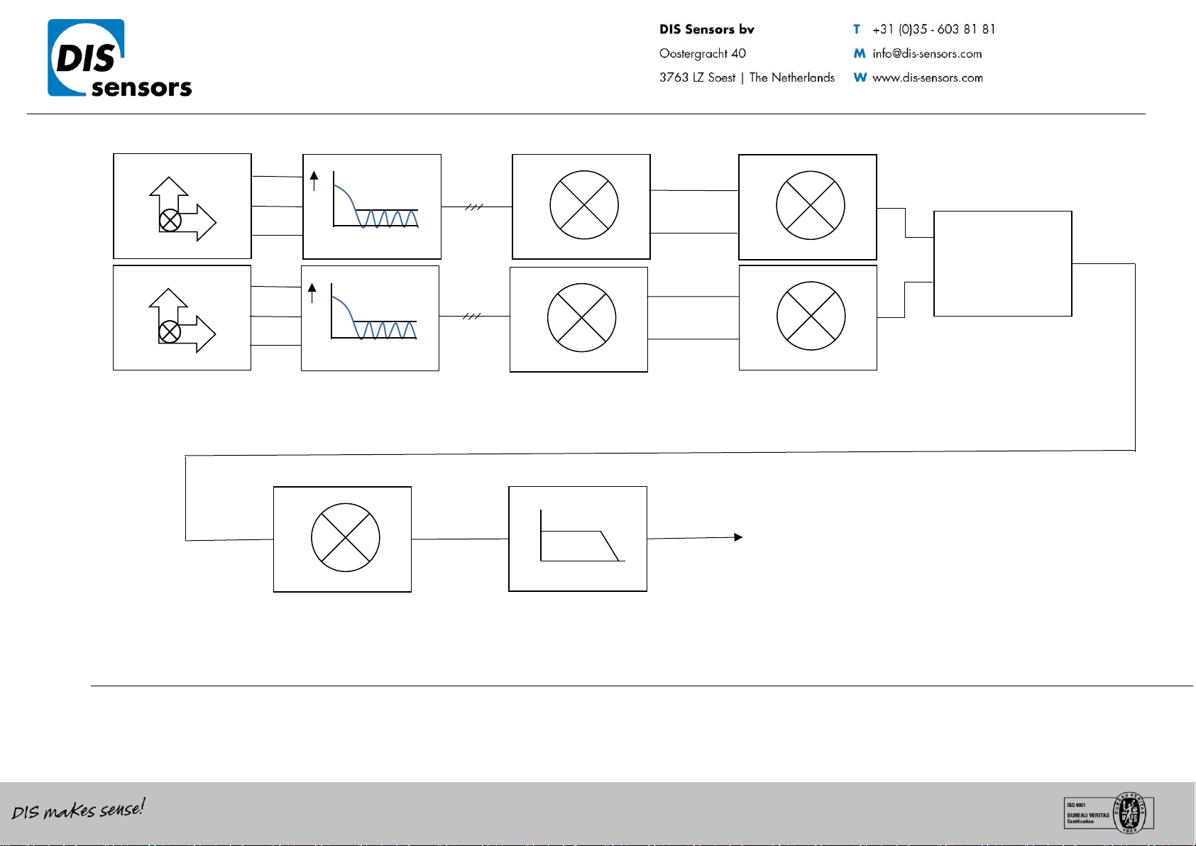
8.1 Sample rate:
The internal g-sensor chip is sampled every 10ms. Each sample of the element consists of 16 samples for each
axis. Resulting in sample rate of 1600 Hz. These samples are input for a 32 tabs FIR input low pass filter. Each
10ms new data is available for the CAN bus.
8.2 Averaging:
The FIR filtered values are averaged during the TPDO1 cycle time set by the customer. A longer TPDO cycle time
results is a smaller bandwidth and therefore a more stable output signal (less noise), but also more phase delay.
e.g. if Event time TPDO1 is 10 ms (fastest time) à a filtered value of 16 samples is available.
e.g. if Event time TPDO1 is 100 ms à an average value of 10*16 samples is available.
8.3 Output filter:
The output of the sensor can be extra filtered by a 1st order low-pass filter. Default this output filter is disabled.
Via the CAN object dictionary (index 300Eh) this filter can be controlled, by setting the time-constant in ms, with
a maximum of the redundancy compare time (set by index 4006h sub-index 02h) .
The time constant is defined as the time in which the output changes to 70% of the step after a step response.
The -3dB frequency can be calculated by the formula f = 1 / (2*pi*time-constant). This -3dB frequency is
independent of a change in TPDO1 event time and the SRDO refresh time. But when the output filter time-
constant is set < min. [TPDO1 event time, the SRDO refresh time], the output filter is disabled. With the factory
default, the filter time-constant can be set within 50ms –2000ms, other value will disable the filter.

Page 7 of 18
CAN User Manual
Inclination Safety Sensor
(Type D) V2.0
8.4 Peak Suppression Filter:
Two Peak Suppression Filters (PSF) are implemented to reduce unwanted disturbances in the inclination
measurement caused by acceleration peaks.
Filter principle: as inclination normally changes relative slow, a sudden peak in the inclination signal indicates an
acceleration peak instead of a real inclination angle change. In this case, the filter can make the sensor ignore
this peak for a certain time.
PSF in the redundancy compare chain (object 4007h):
The redundancy compare chain checks the difference between the two redundant MEMS chips. The filter helps
to prevent for false safety alarms.
PSF in the inclination output chain (object 4008h):
The filter in the output chain makes the inclination output more stable and more realistic
PSF can be adjusted with 2 parameters:
•Angle (°): This parameter sets the threshold for the peak. Only peaks above this threshold will be
filtered. Setting this angle parameter to 0° will disable the PSF
•Time (ms): After the peak suppression filter becomes active, it will hold the inclination signal for a
certain period of time, set by this parameter.
Default values for Object 4007h: on, 3°, 40ms
Default values for Object 4008h: on, 9°, 50ms
8.5 Pre-set/zero adjustment:
To eliminate mechanical offsets a pre-set/ zero value can be added. This can be done with the pre-set/zero
adjustment method, so introducing a permanent offset on the output of the sensor (centre point = middle of
measuring range). The current position will be regarded as the new pre-set/zero position. This can be done
limited to 100.000x. (The value is written in EEPROM. The write actions for EEPROM is limited to 100.000x)
Via CAN object 300Fh (see sensor specific part) the centering/zeroing can be done for each axis separate or for
both axis at the same time. Status information of the result is available from the same object 300Fh
Since the offset has direct influence on the output angle, the pre-set/zero value is protected with a CRC code.
This CRC code must be set via object 63FFh. When the CRC code is written it must be validated with object 63FE
sub id 0 writing data A5h.
The polynomial of the CRC code is:
Table 1 Object fields for zero value (pre-set) CRC calculation
Order
Index
Sub index
Value
Size
Data
1
6200h
00h
Highest sub index supported
1 octet
2
01h
Sub index number
1 octet
3
Safety slope longitudinal offset (pre-set) value
2 octets
4
02h
Sub index number
1 octet
5
Safety slope lateral offset(pre-set) value
2 octets
For CRC calculation a PC tool is developed and can be found on the DIS web site www.dis-sensors.com
We have implemented two different CRC-calculations. Please check your firmware version number first, and then
select the right Firmware version when using the PC-tool.
A CRC code is also oblige for SRDO1 messages. For detailed information about generating see EN 50325-5. This
CRC code can also be calculated with the same PC tool.

Page 8 of 18
CAN User Manual
Inclination Safety Sensor
(Type D) V2.0
8.6 Accelerator element tolerance
The sensor consists of two accelerator elements. The acceleration values of these elements are converted to
angles. These angles are compared and a safe state is set when the elements differ too much. To prevent for
false alarms, a tolerance can be configured. The tolerance consists of allowing an angle deviation during a certain
time.
These values are adjustable via object 4006h sub- index 01h and 02h. The default values are 300d and 200d ( 3°
during 2000 ms). The actual values used by the customer should fit the application involved. Before using this
sensor and with the settings chosen the customer should evaluate risks in order to check whether the chosen
settings satisfies his safety requirements. Manufacturer is not responsible for any damage caused by these
customer-setting, even when the manufacturer defaults are used.
Definitions for the Redundancy error:
‘Redundancy Compare time’ (user programmable, default 2000ms)
‘Redundancy Compare angle’ (user programmable, default 3°)
8.7 Output invalid
A vertical device measures the angle relative to the gravity. When a device is tilted towards the horizontal plane
for more than 45°, the angle can’t be accurately measure because the gravitation vectors become shorter. In this
case the output is set to 200°. This value indicates that the output is invalid.
For horizontal devices the same principle is valid. When the longitudinal axis is greater than 45 degree the output
for lateral axis is set to 200°. When the lateral axis is greater than 45° the longitudinal is set to 200°. The output is
also invalid when the range limits are reached. Example when angle is 32° for a ±30 device the output is limit to
±30°. For a ±90 device the angle is limited to ±90°.
8.8 Writing objects
When writing an object it can have a major influence on the output. To prevent unauthorized changes most write
action can only be executed when the device is in pre-operational state. According to EN 50325-5
8.9 Changing SRDO1 settings
When changing an SRDO1 setting the sensor must be in pre-operating state.
The direction 1301h sub id 01h must be disabled by writing 00h to object 1301h sub id 01h.
When the SRDO setting is changed the CRC code must also be changed and activated. Finally the data must be
stored in EEPROM
Example to change SRDO1 refresh time
Load object: 1301h sub id 01h with: 00h disable SRDO1 communication.
Load object: 1301h sub id 02h with: 0064h new SRDO1 refresh time.
Load object: 1301h sub id 01h with: 01h enable transmit SRDO1 communication.
Load object: 13FFh sub id 01h with: xxxxh code from CRC calculation tool.
Load object: 13FEh sub id 00h with: A5h validate new CRC.
Load object: 1010h sub id 01h with: “save” or 65766173h write new SRDO1 refresh time, CRC and
validation to EEPROM.
After a power reset and when the device is set to operational, the transmission time is equal to the desired time.

Page 9 of 18
CAN User Manual
Inclination Safety Sensor
(Type D) V2.0
9Internal diagnostic tests
To ensure safety the hard- and software of the safety sensor is continue checked. When a failure is detected, an
emergency message is sent. After sending this message, the device goes to a safe state, in which no
communication is possible (No SRDO, TPDO and Heartbeat). In this state, a NMT reset will not restart the sensor.
Failure should be analyzed by reading out the emergency message. If the error can be fixed, give the sensor a
new power cycle will restart the communication. If it is a ‘sensor element error (redundancy error), you
might consider to update ‘redundancy compare time’ and/or ‘redundancy compare angle. If the error cannot be
fixed, please contact your distributor.
The receiving application should detect that no communication is possible and shall set the system to a safe
state.
Table 2: Emergency code
CAN Connection Object ID: 080h+NODE_ID (emergency message)
Byte number
Type
Description
01h and 00h
U16
Error-code:
0000h: no error
FF00h: CAN Open device specific error code
02h
U8
Error-register:
00h: no error
01h: error register object 1001h
04h and 03h
U8
Diagnose error CAN stack:
0000h: No error
0001h: Reset state
0002h: Can driver has to be reset
0004h: Safety cycle is ready
0008h: reserved
0010h: Timeout by watchdog diagnose
0020h: Overvoltage
0040h: Unknown interrupt occurs
0080h: CSC stack has entered safety stop
0100h: Initialization error
0200h: Can error
0400h: CAN NMT state error
0800h: Diagnose error
1000h: Safety cycle error
2000h: SRDO error
4001h: RAM error
8000h: Unknown error
-multiple errors can be indicated (bitwise OR-ed) simultaneously.
-when an overvoltage occur the device stays permanent in safe state
05h
reserved
06h
00h
01h
02h
03h
04h
05h
06h
07h
09h
Diagnose error
Start CRC calculation ROM
Check register
Check stack
Check addressing part unit 1
Check addressing part unit 2
Check conditional jumps
Check opcode
Check CRC for SRDO’s
Check time stamp

Page 10 of 18
CAN User Manual
Inclination Safety Sensor
(Type D) V2.0
0Ah
0Bh
0Ch
0Dh
0Eh
0Fh
10h
11h
12h
19h
7Fh
Wait for end of CRC calculation for CSC main
Start CRC calculation ROM for application
Wait for end of CRC calculation for application
Start CRC calculation ROM for start-up monitor
Wait for end of CRC calculation for start-up monitor
Check RAM with GALPAT algorithm
Check software interrupt
Check software interrupt was ok
Check undefined instruction interrupt
Check undefined instruction interrupt was ok
Idle state
07h
00h
01h
02h
04h
08h
10h
20h
40h
80h
Application error
No application error
Unknown interrupt occurs
Safety RAM error
SRDO error
3V3 monitor error
Sensor element error (Redundancy Error)
RAM error
EEPROM error
Watchdog or 5V under voltage error
multiple errors can be indicated (bitwise OR-ed) simultaneously.
Sensor goes to safe state (stop state) when an error is reported. Sensor must be power cycled to restart.
Example:
Receive COB-id 81h with data 00h FFh 01h 80h 00h 00h 0Eh 08h
81 emergency message of node id 01h
00h FFh-> FF00h CAN Open device specific error code
01h-> error register object 1001h
80h 00h ->0080h CSC stack has entered safety stop
00h reserved
0Eh Wait for end of CRC calculation for start-up monitor
08h. 3V3 monitor error
10 CAN Predefined Connection Object ID’s
Table 3: COB id’s
Standard CAN Connection Object ID’s (Most used)
CAN-ID
Data
Description (client = CAN master, server = sensor)
000h
NMT Network Management
080h
Sync command to sensor
080h + node-ID
Emergency message from sensor
0FFh + 2 * node-ID
SRDO1 normal message
100h + 2 * node-ID
SRDO1 inverse message
180h + node-ID
TPDO1 message from sensor
280h + node-ID
TPDO2 message from sensor
580h + node-ID
SDO Download Request: Feedback from sensor (server to client)
600h + node-ID
SDO Upload Request: Write to sensor (client to server)
700h + node-ID
00h
04h
05h
7Fh
heartbeat from sensor, boot-up mode
heartbeat from sensor, stopped mode
heartbeat from sensor, operational mode
heartbeat from sensor, pre-operational mode
Page 11 of 18
CAN User Manual
Inclination Safety Sensor
(Type D) V2.0
11 CAN Object Dictionary Entries (Communication Profile section)
Table 4: Communication profile section
Index
Sub-
index
Type
Read/
Write
Data
Description
Pre-
operational
1000h
00h
U32
R
3001019Ah
3002019Ah
Device Type
= Inclination, C1 (360°) normal TPDO
= Inclination, C2 (±90° or ±30°) normal TPDO
No
1001h
00h
U8
R
e.g. 00h
e.g. 81h
Error Register
= Normal operation
= Device error
No
1003h
00h
U32
R
Predefined error field
No
1005h
00h
U32
R+W
COB-ID SYNC
No
100Ch
00h
U16
R
Guard time
No
100Dh
00h
U8
R
Life time factor
No
1010h
00h
U8
R
3
Number of entrees
No
01h
U32
R+W
“save” in ASCII
Or “65766173h”
Save all parameters in EEPROM
Yes
02h
U32
R+W
“save” in ASCII
Or “65766173h”
Save communication parameters in EEPROM
Yes
03h
U32
R+W
“save” in ASCII
Or “65766173h”
Save application parameters in EEPROM
Yes
1011h
00h
U8
R
3
Number of entrees
No
01h
U32
R+W
“load” in ASCII
Or “64616F6Ch”
Restore all parameters from EEPROM
Yes
02h
U32
R+W
“load” in ASCII
Or “64616F6Ch”
Restore communication parameters from
EEPROM
Yes
03h
U32
R+W
“load” in ASCII
Or “64616F6C h”
Restore application parameters from EEPROM
Yes
1017h
00h
U16
R+W
e.g. 07D0h/2000d
e.g. 0000h
Heartbeat time (ms)
= 2000 ms
= 0 ms (heartbeat switched off, default)
No
1018h
01h
U32
R
4
Vendor ID (000001BDh)
No
02h
U32
R
e.g.04000001h
e.g.04000002h
e.g.04000003h
Product Code
= Inclination 1-axis (vertical plane): 360°
= Inclination 2-axis (horizontal plane): 2x ±90°
= Inclination 2-axis (horizontal plane): 2x ±30°
No
03h
U32
R
e.g. 00020001h
Firmware version sensor (000x000yh)
= v2.1
No
04h
U32
R
e.g. 00000000h
up to FFFFFFFFh
Serial number sensor (32 bit, unique)
No
1300h
00h
U8
R+W
e.g. 00h
e.g. 01h
GFC parameter
= Invalid
= Valid
No
1301h
00h
U8
R
6
Number of entrees SRDO1 communication
parameter
No
01h
U8
R+W
00h
01h
02h
SRDO1 direction
= Disabled
= Tx/SRDO producer (default)
= RX/SRDO consumer
Yes
02h
U16
R+W
e.g. 50h/80d
SRDO1 refresh time/SCT
= 80 ms default
Yes
03h
U8
R+W
e.g. 14h/20d
Safety-relevant validation time (SRVT)
= 20 ms default
Yes
04h
U8
R+W
e.g. FEh/254d
Transmission type
= Asynchronous (default)
Yes

Page 12 of 18
CAN User Manual
Inclination Safety Sensor
(Type D) V2.0
Index
Sub-
index
Type
Read/
Write
Data
Description
Pre-
operational
05h
U32
R+W
e.g. 101h
COB-ID1
0xFFh + Node ID *2 (default)
Yes
06h
U32
R+W
e.g. 102h
COB-ID2
0x100h + Node ID *2 (default)
Yes
13FEh
00h
U8
R+W
e.g. A5h
Other value
SRDO configuration
= SRDO configuration signature valid
= SRDO configuration signature not valid
Yes
13FFh
00h
U8
R
4
Number of entrees
No
01h
U16
R+W
CRC of SRDO1
Yes
1400h
00h
U8
R
2
Number of entrees Receive PDO 1
No
01h
U32
R+W
C0000201h
COB-ID used by RPDO1
= RPDO1 disabled
No
02h
U8
R+W
FFh
Transmission type
= event-driven (default)
No
1401h
00h
U8
R
2
Number of entrees Receive PDO 2
No
01h
U32
R+W
C0000301h
COB-ID used by RPDO2
= RPDO2 disabled
No
02h
U8
R+W
FFh
Transmission type
= event-driven (default)
No
1600h
00h
U8
R
00h
Receive PDO mapping
= Mapping disabled
No
01h-
08h
U32
R
00000000h
= Disabled
No
1601h
00h
U8
R
8
Number of entrees Receive PDO mapping
No
01h-
08h
U32
R
00000000h
= Disabled
No
1800h
00h
U8
R
5
Number of entrees
No
01h
U32
R+W
e.g. 40000181h
e.g. C0000181h
TPDO1 event-mode
= Enable
= Disable (default)
No
02h
U8
R+W
e.g. 01h
e.g. FFh
TPDO1 sync-mode
= Enable
= Disable (default)
No
05h
U16
R+W
e.g. 0032h/50d
e.g. 0000h
TPDO1 event-time (time in ms )
= 50 ms (default)
= 0 ms (disable TPDO1)
(Max. = 5000ms)
No
1801h
00h
U8
5
Number of entrees
No
01h
U32
R+W
e.g. 40000281h
e.g. C0000281h
TPDO2 event-mode
= Enable
= Disable (default)
No
02h
U8
R+W
e.g. 01h
e.g. FFh
TPDO2 sync-mode
= Enable
= Disable (default)
No
05h
U16
R+W
e.g. 0032h/50d
e.g. 0000h
TPDO2 event-time (time in ms)
= 50 ms (default)
= 0 ms (disable TPDO2)
(Max. = 5000ms)
No
To store communication specific parameters permanent into the EEPROM of the sensor CAN Object 1010h should be used,
otherwise the changes will be lost after a power cycle.
All not-specified indices and/or sub-indices are reserved for factory use only.

Page 13 of 18
CAN User Manual
Inclination Safety Sensor
(Type D) V2.0
12 CAN Object Dictionary Entries 360v device
(Application Specific Profile section)
Table 5 Application specific profile section for 360 degree device
Index
Sub
index
Type
Read/
Write
Data
Description
Pre-
operational
1381h
00h
U8
R
4
Number of entrees
No
01h
U32
R
e.g. 62100108h
SR application data object 1 (normal)
= Normal longitudinal bit 0-7
No
02h
U32
R
e.g. 62110108h
SR application data object 1(inverse)
= Inverse longitudinal bit 0-7
No
03h
U32
R
e.g. 62100208h
SR application data object 2 (normal)
= Normal longitudinal bit 8-15
No
04h
U32
R
e.g. 62110208h
SR application data object 2 (inverse)
= Inverse longitudinal bit 8-15
No
3000h
00h
U8
R
1
Number of entrees
No
01h
U8
R+W
01h up to 7Fh
Node-ID
01h (default) up to 7Fh
(when Node-ID >3Fh non-standard COB-ID of SRDO1
must be used)
(changes are being affected after a power cycle only)
Yes
3001h
00h
U8
R
1
Number of entrees
No
01h
U8
R+W
e.g.06h
e.g.05h
e.g.04h
e.g.03h
e.g.02h
e.g.01h
e.g.00h
Baud rate (kbit/s)
= 50
= 100
= 125 (default)
= 250
= 500
= 800
= 1000
(changes are being affected after a power cycle only)
Yes
300Eh
00h
U8
R
1
Number of entrees
No
01h
U16
R+W
Time in ms
e.g. 0000h
e.g. 0064h/100d
Output filter (1st order low pass filter):
= Disabled (default)
= Enabled, 100 ms (f=1.59 Hz)
(Max. = ‘redundancy compare time’)
Yes
300Fh
00h
U8
R
1
Number of entrees
No
01h
S8
R+W
e.g. 01h
Pre-set adjustment angle.
Write 01h: start zero longitudinal
Read 00h= zero successful,
Read FFh= zero unsuccessful
Yes
4006h
00h
U8
R
2
Number of entrees
No
01h
U16
R+W
e.g. 012Ch/300d
e.g. 001Eh/30d
Redundancy Compare Angle
(Maximal angle deviation between two elements)
= 3,00° (default)
= 0,3°
(Max. = 18°)
Yes
02h
U16
R+W
e.g. 00C8h/200d
Redundancy Compare Time [x10 ms]
(Time within maximal deviation is allowed)
= 2000 ms (default)
(Max. = 10 s)
Yes
Page 14 of 18
CAN User Manual
Inclination Safety Sensor
(Type D) V2.0
Index
Sub
index
Type
Read/
Write
Data
Description
Pre-
operational
4007h
00h
U8
R
1
Number of entrees
No
01h
U16
R+W
e.g. 0000h
e.g. 012Ch/300d
Peak suppression redundancy angle
= Disabled
= 3° (default)
(Min. = 3°)
Yes
02h
U16
R+W
e.g. 0004h/4d
e.g. 03E8h/1000d
Peak suppression redundancy time [x10 ms].
= 40 ms (default)
(Max. = 10 s)
Yes
4008h
00h
U8
R
1
Number of entrees
01h
U16
R+W
e.g. 0000h
e.g. 0384h/900d
e.g. 012Ch/300d
Peak suppression output angle
= Disabled
= 9° (default)
(Min.= 3°)
02h
U16
R+W
e.g. 0005h
e.g. 0032h/50d
e.g. 03E8h/1000d
Peak suppression output time [x10 ms].
= 50 ms (default)
= 500 ms
(Max. = 10 s)
6000h
00h
U8
R
e.g. 000Ah/10d
Resolution = 0,01°
No
6010h
00h
S16
R
Longitudinal slope
No
6011h
00h
U8
R+W
e.g. Bit0 = 0
e.g. Bit0 = 1
e.g. Bit1 = 0
e.g. Bit1 = 1
Other bits
Operating parameter longitudinal slope
= Slope normal
= Slope inverse
= Pre-set disabled
= Pre-set enabled
= No function
Yes
6200h
00h
U8
R
2
Number of entrees
No
01h
S16
R+W
Pre-set value longitudinal
Yes
02h
S16
R+W
Pre-set value lateral
Yes
6210h
00h
U8
R
2
Number of entrees
No
01h
U8
R
Bit 0-7 of normal SRDO longitudinal slope
No
02h
U8
R
Bit 8-15 of normal SRDO longitudinal slope
No
6211h
00h
U8
R
2
Number of entrees
No
01h
U8
R
Bit 0-7 of inverse SRDO longitudinal slope
No
02h
U8
R
Bit 8-15 of inverse SRDO longitudinal slope
No
63FEh
00h
U8
R+W
e.g. A5h
e.g. 00h
Pre-set configuration field
= Signature valid
= Signature not valid
Yes
63FFh
00h
U8
R
1
Number of entrees
No
01h
U16
R+W
Pre-set value signature
Yes
To store application specific parameters permanent into the EEPROM of the sensor CAN Object 1010h should be used, otherwise
the changes will be lost after a power cycle.
All not-specified indices and/or sub-indices are reserved for factory use only.

Page 15 of 18
CAN User Manual
Inclination Safety Sensor
(Type D) V2.0
13 CAN Object Dictionary Entries ±30h and ±90h devices
(Application Specific Profile section)
Table 6: Application specific profile section for ±30h and ±90h devices
Index
Sub
index
Type
Read/
Write
Data
Description
Pre-
operational
1381h
00h
U8
R
8
Number of entrees
No
01h
U32
R
e.g. 62100108h
SRDO1 mapping object 1 (normal)
= Normal longitudinal bit 0-7
No
02h
U32
R
e.g. 62110108h
SRDO1 mapping object 1 (inverse)
= Inverse longitudinal bit 0-7
No
03h
U32
R
e.g. 62100208h
SRDO1 mapping object 2 (normal)
= Normal longitudinal bit 8-15
No
04h
U32
R
e.g. 62110208h
SRDO1 mapping object 2 (inverse)
= Inverse longitudinal bit 8-15
No
05h
U32
R
e.g. 62200108h
SRDO1 mapping object 3 (normal)
= Normal lateral bit 0-7
No
06h
U32
R
e.g. 62210108h
SRDO1 mapping object 3 (inverse)
= Inverse lateral bit 0-7
No
07h
U32
R
e.g. 62200208h
SRDO1 mapping object 4 (normal)
= Normal lateral bit 8-15
No
08h
U32
R
e.g. 62210208h
SRDO1 mapping object 4 (inverse)
= Inverse lateral bit 8-15
No
3000h
00h
U8
R
1
Number of entrees
No
01h
U8
R+W
01h up to 7Fh
Node-ID
(When Node Id >3Fh non-standard COB-ID of SRDO1
must be used)
(Changes are being affected after a power cycle only)
Yes
3001h
00h
U8
R
1
Number of entrees
No
01h
U8
R+W
e.g. 06h
e.g. 05h
e.g. 04h
e.g. 03h
e.g. 02h
e.g. 01h
e.g. 00h
Baud rate (kbit/s)
= 50
= 100
= 125 (default)
= 250
= 500
= 800
= 1000
(Changes are being affected after a power cycle only)
Yes
300Eh
00h
U8
R
1
Number of entrees
No
01h
U8
R+W
Time in ms
e.g. 0000h
e.g. 0064h
Output filter (1st order low pass):
= Disabled (default)
= Enabled, 100 ms (f=1.59 Hz)
(Max. = ‘redundancy compare time’)
Yes
300Fh
00h
U8
R
1
Number of entrees
No
01h
S8
R+W
e.g. Write 01h
e.g. Write 02h
e.g. Write 03h
e.g. Read 00h
e.g. Read FFh
e.g. Read FEh
Pre-set adjustment
= start zero longitudinal
= start zero lateral
= start longitudinal and lateral
= zero successful,
= fail zero longitudinal
= fail zero lateral
Yes
4006h
00h
U8
R
1
Number of entrees
No
01h
U16
R+W
e.g. 012Ch/300d
Redundancy Compare Angle
(Maximal angle deviation between two elements)
= 3,00° (default)
(Max = 3° (±30h) / 9° (±90h))
Yes
02h
U16
R+W
e.g. 00C8h/200d
Redundancy Compare Time [x10ms].
(Time within maximal deviation is allowed)
= 2000 ms (default)
(Max. = 10 s)
Yes

Page 16 of 18
CAN User Manual
Inclination Safety Sensor
(Type D) V2.0
Index
Sub
index
Type
Read/
Write
Data
Description
Pre-
operational
4007h
00h
U8
R
1
Number of entrees
No
01h
U16
R+W
e.g. 0000h
Peak suppression redundancy angle
= Disabled
= 3° (default)
(Min. = 3°)
Yes
02h
U16
R+W
e.g. 0004h/04d
Peak suppression redundancy time [x10 ms].
= 40 ms (default)
(Max. = 10 s)
Yes
4008h
00h
U8
R
1
Number of entrees
01h
U16
R+W
e.g. 0000h
e.g. 0384h/900d
Peak suppression output angle
= Disabled
= 9° (default)
(Min. = 3°)
02h
U16
R+W
e.g. 0005h/5d
Peak suppression output time [x10 ms].
= 50 ms (default)
(Max. = 10 s)
6000h
00h
U8
R
e.g. 0Ah/10d
Resolution
= 0,01°
No
6010h
00h
S16
R
Longitudinal slope
No
6011h
00h
U8
R+W
e.g. Bit0 = 0
e.g. Bit0 = 1
e.g. Bit1 = 0
e.g. Bit1 = 1
e.g. Other bits
Operating parameter longitudinal slope
= Slope normal
= Slope inverted
= Pre-set disabled
= Pre-set enabled
= No function
Yes
6020h
00h
S16
R
Lateral slope
No
6021h
00h
U8
R+W
e.g. Bit0 = 0
e.g. Bit0 = 1
e.g. Bit1 = 0
e.g. Bit1 = 1
e.g. Other bits
Operating parameter lateral slope
= Slope normal
= Slope inverted
= Pre-set disabled
= Pre-set enabled
= No function
Yes
6200h
00h
U8
R
2
Pre-set value
No
01h
S16
R+W
Pre-set value longitudinal
Yes
02h
S16
R+W
Pre-set value lateral
Yes
6210h
00h
U8
R
2
Number of entrees
No
01h
U8
R
Bit 0-7 of normal SRDO longitudinal slope
No
02h
U8
R
Bit 8-15 of normal SRDO longitudinal slope
No
6211h
00h
U8
R
2
Number of entrees
No
01h
U8
R
Bit 0-7 of inverse SRDO longitudinal slope
No
02h
U8
R
Bit 8-15 of inverse SRDO longitudinal slope
No
6220h
00h
U8
R
2
Number of entrees
No
01h
U8
R
Bit 0-7 of normal SRDO lateral slope
No
02h
U8
R
Bit 8-15 of normal SRDO lateral slope
No
6221h
00h
U8
R
2
Number of entrees
No
01h
U8
R
Bit 0-7 of inverse SRDO lateral slope
No
02h
U8
R
Bit 8-15 of inverse SRDO lateral slope
No
63FEh
00h
U8
R+W
A5h
00h
Pre-set configuration field
= Signature valid
= Signature not valid
Yes
63FFh
00h
U8
R
1
Number of entrees
No
01h
U16
R+W
Pre-set value signature
Yes
To store application specific parameters permanent into the EEPROM of the sensor CAN Object 1010h should be used, otherwise,
the changes will be lost after a power cycle.
All not-specified indices and/or sub-indices are reserved for factory use only.

Page 17 of 18
CAN User Manual
Inclination Safety Sensor
(Type D) V2.0
14 EDS files
The “Electronic Data Sheet” (EDS file) is a file format that describes the communication behavior and the object
dictionary entries of a device. In fact it’s a template. This allows tools such as CAN configuration tools to handle
the device properly. The file format is described in CiA306 V1.3.0
The EDS-file contains all possible settings and functions for the device by describing the CAN object dictionary
for the device to be set by CAN commands.
The EDS-file does not contain a customer specific configuration description (the values of the object dictionary,
like i.e. the chosen baud rate, TPDO1 event time, Node ID etc.). For this purpose the customer can generate a so
called DCF-file (Device Configuration File) with all customer specific settings out of the EDS-file. The DCF file is in
fact the incarnation of the EDS-file.
After loading the DCF-file into the device you have to store the settings into EEPROM by index 1010h sub index
01h to store permanently, see “CAN Object Dictionary Entries”.
The EDS-files available for sensors with embedded firmware version D-type described in this document should
have a version D-type also.
The next EDS-files are available at www.dis-sensors.com under ‘downloads’:
•QG_Dtype_1_axis_360v_v*.*
•QG_Dtype_2_axis_30h_v*.*
•QG_Dtype_2_axis_90h_v*.*
15 Document revision control
V1.0 first release
V1.1 Add SRD1 objects programming. Add Writing objects in pre-operating state. Major text additions
V1.2 Add commend after review JK
V1.3 Safety information added (MvA)
V1.4 Layout changed (RMo), safety chapters modified (MvA)
V1.5 Change mapping object 1381h for 1 axis and 2 axis according to profile (RMo)
V1.6 20190725 Various more accurate descriptions, some parameters maximized, see release notes firmware
v2.9 & v2.5.3
V1.7 20200831 Insert Peak suppression filter for MEMS elements and for inclination output (MvA)
V1.8 20210823 correct proof test period and pre-set disable/enable(SX).
V1.9 20210917 Re-certification / EC type examination by DEKRA successful. New certificate nr.
V2.0 20220321 Add max. redundancy compare angle.(SX)
CAN User Manual Inclination Safety Sensor
(Type D)V2.0
Page 18 of 18
A. Appendixes1 Schematic overview inclination measurement
Figure 2: Schematic overview inclination measurement.
800Hz
100Hz
0
-45
dB
800Hz
100Hz
0
-45
dB
∑
Fs = 1600 Hz
Sample rate 1600 Hz
32 taps FIR filter
45 dB suppression.
Sample rate 10 ms
Offset and gain
correction.
Calculate angle
Lookup correction.
Compare sensor
elements
Perform PSF in redundancy
chain and then
Average the two
sensor elements
Zero (pre-set) correction.
Output according profile
Perform PSF in output chain
1st order low pass
Fcut-off = 1 / (filter-time*2*pi)
(adjust response with object
300Eh)
X counts
Y counts
Z counts
X counts
Y counts
Z counts
X Y Z filtered
X Y Z filtered
Longitudinal
angle in degree
Lateral angle in
degree
Longitudinal
angle in degree
Lateral angle in
degree
Output angles
Corrected angles
in degree
Table of contents
Other DIS Sensors Accessories manuals


Popular Accessories manuals by other brands

Actelser
Actelser ACT1002 installation instructions

Homematic IP
Homematic IP HmIP-SWDM Mounting instruction and User manual

AFK
AFK EB-100.1D instruction manual

Amcrest
Amcrest SmartHome AD410 installation guide

Axminster
Axminster woodturning 310404 quick start guide

Bodet
Bodet HARMONYS Flash Installation and user manual


