BBH SCU Series Owner's manual
Programming manual SCU-series
HB-37500-820-10-12F-EN SCU Programming manual Page 1 of 252
Status: 19.03.2021
Programming manual
For the
SCU-series
With SafePLC2

Programming manual SCU-series
HB-37500-820-10-12F-EN SCU Programming manual Page 2 of 252
Status: 19.03.2021
NOTES:
The German version is the original version of the programming manual.
Subject to modification!
The content of this documentation has been compiled extremely carefully according to our current
level of information.
Nevertheless, we indicate that this document cannot always be updated simultaneously with the
technical progress. Information and specifications can be changed at any time. For the current
version, please consult www.bbh-products.de.
Manufacturer information:
BBH Products GmbH
Böttgerstraße 40
D-92637 Weiden
GERMANY
Phone: +49(0)961-48244-0
E-mail: [email protected]
Web: www.bbh-products.de
Responsible for the compilation of the documents:
Gerhard Bauer, Managing Director BBH Products
This document is subject to German copyright. Copying, processing, and any kind of use
beyond the limits of copyright require the written consent of the respective author or
creator.
INFORMATION:
Before programming the unit, the unit must be completely installed and put into operation. For this
purpose, all connected components must be installed and put into operation, and the connections
must be connected. For installing, putting into operation and connecting, please read and observe
the SCU installation manual.
INFORMATION:
The documentation (installation manual, programming manual) are disposable via the download of
BBH Products GmbH.

Programming manual SCU-series
HB-37500-820-10-12F-EN SCU Programming manual Page 3 of 252
Status: 19.03.2021
1. Tables
1.1. Table of contents
1. Tables ........................................................................................................... 3
1.1. Table of contents .............................................................................................. 3
1.2. Register of illustrations...................................................................................... 9
2. Basic information....................................................................................... 15
2.1. Important information for use ...........................................................................15
2.2. Scope of delivery .............................................................................................15
2.3. Terms ..............................................................................................................15
2.4. Symbols and signal words ...............................................................................16
2.5. Valid documents : ............................................................................................16
2.6. General safety information ...............................................................................17
3. Requirements............................................................................................. 18
3.1. SCU unit ..........................................................................................................18
3.2. Network connection .........................................................................................18
3.2.1. EtherCAT.........................................................................................................18
3.2.1.1. EtherCAT data transfer ....................................................................................19
3.2.2. FSoE................................................................................................................19
3.2.3. FSoE and EtherCAT ........................................................................................20
4. Selecting and parameterizing the SCU via SafePLC² ............................. 21
4.1. Terms ..............................................................................................................21
4.2. Installation........................................................................................................24
4.2.1. System requirements .......................................................................................24
4.2.2. Installation process ..........................................................................................25
4.2.3. Hardlock ..........................................................................................................28
4.2.4. Uninstalling ......................................................................................................28
4.2.5. Running Application .........................................................................................28
4.3. User interface ..................................................................................................29
4.3.1. Main window....................................................................................................29
4.3.2. Customizing the main window..........................................................................30
4.3.2.1. Layout reset.....................................................................................................30
4.3.2.2. Docking............................................................................................................30

Programming manual SCU-series
HB-37500-820-10-12F-EN SCU Programming manual Page 4 of 252
Status: 19.03.2021
4.3.2.3. Automatic hide .................................................................................................31
4.3.3. Title bar............................................................................................................32
4.3.4. Start menu .......................................................................................................33
4.3.5. Menu of the ribbon...........................................................................................35
4.3.5.1. Start.................................................................................................................36
4.3.5.2. Windows ..........................................................................................................37
4.3.5.3. Filters...............................................................................................................40
4.3.6. Status bar ........................................................................................................41
4.3.7. Mouse commands and keyboard commands...................................................41
4.3.7.1. Mouse-independent actions .............................................................................41
4.3.7.2. Keyboard commands .......................................................................................42
4.3.8. Browser (library window)..................................................................................43
4.3.9. Control via document tabs ...............................................................................44
4.3.10. Plan types........................................................................................................46
4.3.10.1. Terminal Scheme.............................................................................................46
4.3.10.2. Wiring scheme .................................................................................................47
4.3.10.3. Functional scheme...........................................................................................48
4.3.10.3.1. Groups.............................................................................................................48
4.3.10.4. Global Network ................................................................................................48
4.3.10.5. Local Network..................................................................................................48
4.3.11. Work surface....................................................................................................49
4.3.12. Library window.................................................................................................50
4.3.13. Properties window............................................................................................51
4.3.13.1. Structure of the properties window...................................................................53
4.3.13.2. “Extended Properties” menu ............................................................................54
4.3.13.3. Validation of properties ....................................................................................55
4.3.13.3.1. Input validation.................................................................................................55
4.3.13.3.2. Value validation ...............................................................................................56
4.3.13.3.3. Adaption ..........................................................................................................56
4.3.14. Message window .............................................................................................57
4.3.14.1. Quickly jump to an element..............................................................................57
4.3.14.2. Search field......................................................................................................57
4.3.14.3. Context menu in the message window.............................................................58

Programming manual SCU-series
HB-37500-820-10-12F-EN SCU Programming manual Page 5 of 252
Status: 19.03.2021
4.3.15. Global search...................................................................................................58
4.3.15.1. Search settings ................................................................................................59
4.3.15.2. Quickly jump to an element..............................................................................59
4.3.16. Print .................................................................................................................60
4.3.17. Settings............................................................................................................62
4.3.18. Auto Recovery .................................................................................................64
4.3.19. Information concerning the program.................................................................65
4.3.20. Window “User Rights Dialog” ...........................................................................65
4.3.20.1. Tab “Users”......................................................................................................66
4.3.20.2. Tab “Gruppen“ [Groups]...................................................................................66
4.4. Process............................................................................................................67
4.4.1. General workflow .............................................................................................67
4.4.2. Network plan....................................................................................................73
4.4.3. Selecting the units / network components ........................................................76
4.4.4. FSoE settings of the units / the network options...............................................78
4.4.5. Optional Fieldbus interface ..............................................................................78
4.4.6. Determining the inputs and the outputs of the units..........................................81
4.5. Determining the functions ................................................................................84
4.6. Embedding of existing Slaves from external companies...................................85
4.6.1. General information .........................................................................................85
4.6.2. Adjusting the Slaves ........................................................................................85
4.6.2.1. SDC (LT-i)........................................................................................................85
4.6.2.2. EL1904, EL2904, AX5805, AX5806 (Beckhoff) ................................................88
4.6.3. Embedding not pre-defined Slaves ..................................................................91
4.6.4. Adding input elements .....................................................................................91
4.6.5. Inserting output elements.................................................................................91
4.6.6. The logic modules............................................................................................92
4.6.7. Circuit ..............................................................................................................92
4.6.8. Using groups....................................................................................................94
4.6.9. Creating a program..........................................................................................94
4.6.10. Transferring the program to the device ............................................................96
4.6.10.1. Connection settings: ........................................................................................97
4.6.11. Diagnostics ......................................................................................................98

Programming manual SCU-series
HB-37500-820-10-12F-EN SCU Programming manual Page 6 of 252
Status: 19.03.2021
4.6.11.1. Diagnosis process in the function block diagram............................................100
4.6.11.1.1. Diagnosis in the work surface ........................................................................100
4.6.11.1.2. Diagnosis in the Function Block tab ...............................................................100
4.6.12. Scope Onlinediagnostics................................................................................103
4.6.12.1. Procedure of a measuring in the range ..........................................................106
4.6.12.2. Preparing measurement.................................................................................106
4.6.12.3. Starting measurement....................................................................................106
4.6.12.4. Stopping measurement and indicating data ...................................................106
4.6.12.5. Measurement plans .......................................................................................107
4.7. Configuration report .......................................................................................110
4.8. User management .........................................................................................114
4.9. Device interface .............................................................................................115
4.10. Export window ...............................................................................................117
4.11. Networks........................................................................................................127
4.11.1. Master to Master (SMMC)..............................................................................127
4.11.1.1. Description.....................................................................................................127
4.11.1.2. Creation .........................................................................................................127
4.11.1.3. Configuration .................................................................................................129
4.11.1.4. Use ................................................................................................................131
4.11.2. Fieldbus .........................................................................................................133
4.11.2.1. Description.....................................................................................................133
4.11.2.2. Creation .........................................................................................................133
4.11.2.3. Configuration .................................................................................................134
4.12. Fastchannel ...................................................................................................139
4.12.1.1. Description.....................................................................................................139
4.12.1.2. Creating a FastChannel connection ...............................................................139
4.12.1.3. Device configuration ......................................................................................140
4.12.1.4. User program.................................................................................................141
4.13. Content of the library......................................................................................144
4.13.1. Device modules .............................................................................................145
4.13.1.1. Master devices .....................................................................................145
4.13.1.2. Slave devices .......................................................................................145
4.13.1.3. Peripheral devices .........................................................................................145

Programming manual SCU-series
HB-37500-820-10-12F-EN SCU Programming manual Page 7 of 252
Status: 19.03.2021
4.13.2. Input elements ...............................................................................................146
4.13.2.1. List of input elements .....................................................................................149
4.13.2.2. Listing of the startup types via the “Enable” button.........................................154
4.13.3. Output blocks.................................................................................................156
4.13.3.1. List of output elements...................................................................................157
4.13.4. Encoder combinations ...................................................................................161
4.13.4.1. Setting the encoder‘s range ...........................................................................161
4.13.4.2. Setting the axle ..............................................................................................162
4.13.5. Function block................................................................................................164
4.13.5.1. Logic function.................................................................................................164
4.13.5.2. Safety functions .............................................................................................175
4.13.5.2.1. Overview of safety modules ...........................................................................176
4.13.5.3. Muting functions.............................................................................................213
4.13.5.4. Elements of the global network ......................................................................221
4.13.5.5. Elements of the fieldbus network ...................................................................222
4.13.5.6. Connections...................................................................................................223
4.13.5.7. Groups...........................................................................................................224
4.13.5.7.1. Creating a group: ...........................................................................................225
4.13.5.7.2. Setting the group administration.....................................................................227
4.13.5.7.3. Export / Import of a function group .................................................................228
4.13.5.7.4. Group interface ..............................................................................................228
5. Commissioning ........................................................................................ 230
5.1. Start-up sequence..........................................................................................230
5.2. RESET behaviour ..........................................................................................230
5.3. LED display....................................................................................................231
5.4. Parametrization..............................................................................................231
5.5. Regular functional test ...................................................................................231
5.6. Validation.......................................................................................................232
5.6.1. Generating a validation report........................................................................232
5.6.2. Validating the configuration............................................................................234
5.6.3. Validation of the PLC programme ..................................................................235
5.6.3.1. General information .......................................................................................235
5.6.4. Input elements ...............................................................................................236

Programming manual SCU-series
HB-37500-820-10-12F-EN SCU Programming manual Page 8 of 252
Status: 19.03.2021
5.6.5. Monitoring functions.......................................................................................237
5.6.5.1. Cascading......................................................................................................237
5.6.5.2. Axis groups....................................................................................................238
5.7. Safety-raleted verification...............................................................................240
5.7.1. The validation process ...................................................................................240
6. Failure and troubleshooting.................................................................... 241
7. List of abbreviations................................................................................ 242
8. Appendix................................................................................................... 244
8.1. CoE object list................................................................................................244
8.2. Functional Output...........................................................................................246
8.3. Diagnostics Logbook......................................................................................247
8.4. PLC processing .............................................................................................248
8.4.1. PLC commands .............................................................................................248
8.4.2. Resource assignments...................................................................................249
8.4.3. PLC-operand .................................................................................................251

Programming manual SCU-series
HB-37500-820-10-12F-EN SCU Programming manual Page 9 of 252
Status: 19.03.2021
1.2. Register of illustrations
Figure 1: EtherCAT network ................................................................................................18
Figure 2: FSoE network.......................................................................................................20
Figure 3 user registration.....................................................................................................28
Figure 4 structure of the application window........................................................................29
Figure 5 "window" tab, layout reset......................................................................................30
Figure 6 Personalize the application window by docking ....................................................30
Figure 7 Docking .................................................................................................................31
Figure 8 Automatic hide.......................................................................................................31
Figure 9 context menu.........................................................................................................32
Figure 10 SafePLC2, basic document functions and application functions ..........................33
Figure 11 menu of the ribbon, quick info buttons .................................................................35
Figure 12 Functional Output table........................................................................................38
Figure 13 Document properties ...........................................................................................38
Figure 14 Window “Document properties” Device informations ...........................................39
Figure 15.............................................................................................................................40
Figure 16.............................................................................................................................40
Figure 17 Context menu sheet ............................................................................................45
Figure 18 View “Terminal scheme”......................................................................................46
Figure 19 "Select device" window........................................................................................46
Figure 20 View “wiring scheme“...........................................................................................47
Figure 21 Context menu of the work surfaces......................................................................49
Figure 22 Dragging an item from the library window............................................................50
Figure 23 Properties window with context menu..................................................................51
Figure 24 Properties" window with information about the currently selected property ..........52
Figure 25 strucutre Properties grid ......................................................................................53
Figure 26 Property window with extended Options ..............................................................54
Figure 27 Dialogue ”Export property“...................................................................................54
Figure 28 Exported property on a Master device .................................................................55
Figure 29 Value of the property Number of Input Connectors is not within the range...........55
Figure 30 Example of a value validation. After the property “maximum speed “ has been
changed in 5,.......................................................................................................................56
Figure 31 Example of an adaption. After the property value of “Delay“ has been changed in 4,
the value has been analysed by the adaptation function and has been changed in 8 ..........56

Programming manual SCU-series
HB-37500-820-10-12F-EN SCU Programming manual Page 10 of 252
Status: 19.03.2021
Figure 32 view message window.........................................................................................57
Figure 33 Message window with search field.......................................................................57
Figure 34 message window with context menu...................................................................58
Figure 35 "Global search"....................................................................................................58
Figure 36 Define search settings .........................................................................................59
Figure 37 Tab “Print Preview”.............................................................................................60
Figure 38 User Path tab in the Settings user window...........................................................62
Figure 39 “Lbrary” in Setting option .....................................................................................63
Figure 40 Dialog box "Auto-recovery"..................................................................................64
Figure 41 Tab “User“ in the window “UserRights“. ...............................................................66
Figure 42 Tab “Groups“ in the window „User Rights Dialog“................................................66
Figure 43 Description of the device .....................................................................................68
Figure 44 Property window of the device.............................................................................69
Figure 45 Confirmation button with missing setting (red) .....................................................70
Figure 46 Selection of an input element via the library.........................................................70
Figure 47 Inserting the input module ...................................................................................71
Figure 48 information window..............................................................................................72
Figure 49: example - sketch ................................................................................................74
Figure 50: FSoE-Plan..........................................................................................................75
Figure 51: selection of Master .............................................................................................76
Figure 52: selection of Slaves..............................................................................................77
Figure 53: One sheet per unit ..............................................................................................77
Figure 54: selection of units.................................................................................................78
Figure 55: network selection................................................................................................78
Figure 56: EtherCAT Network..............................................................................................79
Figure 57: FSoE-Optionen für Slaves ..................................................................................79
Figure 58: Insert IO element................................................................................................81
Figure 59: assignment to unit ..............................................................................................81
Figure 60: IO-elemente inserted Master ..............................................................................82
Figure 61: IO-elements inserted Slave1...............................................................................82
Figure 62 Terminal scheme with elements .........................................................................83
Figure 63 Safetyfunctions....................................................................................................84
Figure 64 Library-Slaves SDC (LT-in), EL1904, EL2904, AX5805, AX5806 (Beckhoff) .......85
Figure 65 SDC-symbol wiring plan ......................................................................................85

Programming manual SCU-series
HB-37500-820-10-12F-EN SCU Programming manual Page 11 of 252
Status: 19.03.2021
Figure 66 SDC-parameters..................................................................................................86
Figure 67 SDC axes ............................................................................................................87
............................................................................................................................................87
Figure 68 Properties of the SDU axle(s) ..............................................................................87
Figure 69: EL…. und AX…. In the terminal schemen...........................................................88
Figure 70: IO-Slave-units EL x904 and Axle-Slave units AX580x in the wiring scheme .......88
Figure 71: IO-Slave-units EL x904 with terninal assignment................................................89
Figure 72: Properties of the IO-Slave units EL x904 ............................................................89
Figure 73: Properties of the axle-Slave-units AX 580x.........................................................90
Figure 74 Add segment .......................................................................................................93
Figure 75 function group.....................................................................................................94
Figure 76.............................................................................................................................96
Figure 77 connection settings..............................................................................................97
Figure 78 Diagnostics window of functional module.............................................................98
Figure 79 Diagnosis procedure in the work surface ...........................................................100
Figure 80 Selected blocks on the work surface..................................................................101
Figure 81 Display of the logical state of inputs and outputs in the selected block ..............101
Figure 82 Range view in the device interface ....................................................................103
Figure 83 Overview of the scroll bar for the main diagram.................................................103
Figure 84 Scaling the diagram via the slide bars ...............................................................104
Figure 85 Selecting an output for export............................................................................105
Figure 86 Fields containing device information for the configuration report........................110
Figure 87 Symbols in the device interface –not connected ...............................................115
Figure 88 Symbols –connected ........................................................................................115
Figure 89 connection settings in document properties window ..........................................117
Figure 90...........................................................................................................................118
Figure 91 parameter export, menu "file" ............................................................................118
Figure 92 „Export option“ window ......................................................................................119
Figure 93...........................................................................................................................119
Figure 94 parameter export, menu "edit" ...........................................................................120
Figure 95 User confirmation before resetting parameter values.........................................120
Figure 96 After locking the values, the "Enter password" dialog box appears....................121
Figure 97 parameter export, menu "view"..........................................................................121
Figure 98 export versions of parameters ...........................................................................121

Programming manual SCU-series
HB-37500-820-10-12F-EN SCU Programming manual Page 12 of 252
Status: 19.03.2021
Figure 99 Surface, of disconnected SCU...........................................................................122
Figure 100 Surface if SCU is connected and runs. ............................................................122
Figure 101 parameter export, menu "Validation" ...............................................................123
Figure 102 activated functions by selecting the checkboxes..............................................123
Figure 103 symbols in the device interface –not connected..............................................124
Figure 104 symbols connected..........................................................................................124
Figure 105 "control" tab .....................................................................................................125
Figure 106 „project“ tab .....................................................................................................126
Figure 107 Select "Enable Global Network".......................................................................127
Figure 108 View "global network", SMMC .........................................................................128
Figure 109 "global network", SMMC-line ...........................................................................129
Figure 110 The SMMC properties in the properties window...............................................129
Figure 111 Properties window, master property.................................................................130
Figure 112 Tab "global network"........................................................................................130
Figure 113 .........................................................................................................................131
Figure 114 SMMC Terminal Out........................................................................................131
Figure 115 SMMC Terminal In...........................................................................................132
Figure 116 properties window "local network"....................................................................133
Figure 117 view local network ...........................................................................................133
Figure 118 activated non-safe use.....................................................................................135
Figure 119 .........................................................................................................................135
Figure 120 function block "functional output/message data" ..............................................135
Figure 121 properties window " functional output/message data" ......................................135
Figure 122 functional output with 3 outputs .......................................................................136
Figure 123 Properties window of a functional output..........................................................136
Figure 124 Selection of secure network connections.........................................................137
Figure 125 F-Bus input: function block and properties window ..........................................137
Figure 126 F-Bus Output: function block and properties window .......................................138
Figure 127 properties window "Fieldbus EtherCAT" ..........................................................138
Figure 128 reset from network...........................................................................................138
Figure 129 FastChannel function plan...............................................................................139
Figure 130 FastChannel function plan, FC-connection activated in slave unit properties window
..........................................................................................................................................140
Figure 131 Library window "FastChannel" .........................................................................141

Programming manual SCU-series
HB-37500-820-10-12F-EN SCU Programming manual Page 13 of 252
Status: 19.03.2021
Figure 132 Access ID: selection of Slave number and bit number .....................................142
Figure 133 Access ID: selection of Slave number and bit number merker .........................142
Figure 134 Access ID: selection of bit number of flag ........................................................142
Figure 135 Access ID: selection of bit number of flag ........................................................143
Figure 136 View of the library –terminal scheme selected ................................................144
Figure 137 View of the library –function chart selected.....................................................144
Figure 138 List of input units..............................................................................................146
Figure 139 properties of the confirm button .......................................................................146
Figure 140 Properties of the start element / the reset element...........................................152
Figure 141 Start block / reset block connected with monitored start ..................................154
Figure 142 Start / reset to save and resetzum Speichern und Rücksetzen von Fehlern des
SCA-Moduls über RS-FlipFlop ..........................................................................................155
Figure 143 List of output elements.....................................................................................156
Figure 144 Properties window "HiLo semiconductor"........................................................157
Figure 145 Properties window "Highside semiconductor" .................................................158
Figure 146 Properties window "Relay"...............................................................................159
Figure 147 Output as auxiliary outputs ..............................................................................160
Figure 148 Listing of the logic functions in the library.........................................................164
Figure 149 properties window "AND" block........................................................................165
Figure 150 properties window "EXCLUSIVE OR" block.....................................................165
Figure 151 properties window "FLIP FLOP" block .............................................................166
Figure 152 properties window “cFLIP FLOP” block............................................................167
Figure 153 properties window of logical 1- blocks..............................................................167
Figure 154 properties window of configurable boolean ......................................................168
Figure 155 properties window of NOT function block.........................................................168
Figure 156 properties window of OR function block...........................................................169
Figure 157 properties window „Timer“ ...............................................................................170
Figure 158 properties window of edge detection................................................................172
Figure 159properties window of SEL monitoring................................................................183
Figure 160 properties window of SLP monitoring...............................................................187
Figure 161 properties window of SCA monitoring ..............................................................192
Figure 162 properties window of SSX Monitoring ..............................................................196
Figure 163 properties window of SLI function ....................................................................200
Figure 164 properties window of SDI function....................................................................203

Programming manual SCU-series
HB-37500-820-10-12F-EN SCU Programming manual Page 14 of 252
Status: 19.03.2021
Figure 165 properties window of SLS function...................................................................206
Figure 166 properties window of SOS function..................................................................208
Figure 167 properties window of Multiaxes position monitoring .........................................211
Figure 168 properties window of ECS function ..................................................................213
Figure 169 properties window of ICS function....................................................................214
Figure 170 function time diagram ......................................................................................216
Figure 171 properties window of DEM function..................................................................218
Figure 172 properties window of EOS function..................................................................220
Figure 173 Library window "Global network"......................................................................221
Figure 174 Terminal Out block of SMMC...........................................................................221
Figure 175 Terminal In block of SMMC..............................................................................222
Figure 176 Library window "Fieldbus network" ..................................................................222
Figure 177 Properties window of the connections..............................................................223
Figure 178 Properties window of Terminal out...................................................................224
Figure 179 Group blocked / unblocked ..............................................................................227
Figure 180 Properties "group output "................................................................................228
Figure 181 Example: page 1 configuration report ..............................................................233
Figure 182 Special function SRS.......................................................................................238
Figure 183 Tab "connection" before data are marked as validated ....................................240

Programming manual SCU-series
HB-37500-820-10-12F-EN SCU Programming manual Page 15 of 252
Status: 19.03.2021
2. Basic information
2.1. Important information for use
IMPORTANT!
Read carefully before use!
Please read this instruction manual carefully. Keep it near the machine to consult it in case fo
questions.
This manual is aimed at the following target groups:
▪People projecting safe drive systems: engineers and technicians
▪Assembly, electrical installation, maintenance: industrial electricians and service
technicians
▪Commissioning, operation, configuration: engineers and technicians
2.2. Scope of delivery
The units of the SCU-series are delivered with the plugs for entries or exits and for the voltage
supply (in mated condition).
The corresponding data sheets are attached to the units. The data sheets contain i. a. the
download link for the complete documentation.
INFORMATION:
The documentations (installation manual, programming manual) are freely available via the online
download.
INFORMATION:
Programming software, dongle (hard lock), programming cable etc. must be ordered separately.
2.3. Terms
The term “safe” is used in accordance with or according to the following standards: DIN EN ISO
13849-1, DIN EN 61508-1:2011-02 (cf. the section Relevant standards). “Safe functions for
application to PL e or SIL 3” indicates functions in the sense of the above standards with
corresponding integrity (reliability).
The units SCU, SDU, SIO, SSB manufactured by BBH are units implementing safety relevant
functions with safe communication via FSoE, and unsafe communication by means of EtherCAT.
Internally, these functions are configured as two-channel systems: system A and system B. The
system software SafePLC2serves to program and configure the units SCU, SDU, SIO, SSB
manufactured by BBH.

Programming manual SCU-series
HB-37500-820-10-12F-EN SCU Programming manual Page 16 of 252
Status: 19.03.2021
2.4. Symbols and signal words
Symbol / signal
word
Meaning
Calls your attention to the use and the effects of safety
information.
DANGER
Calls your attention to a dangerous situation causing death or
severe injury if it is not avoided.
WARNING
Calls your attention to a dangerous situation that can cause
death or severe injury if it is not avoided.
CAUTION
Calls your attention to a dangerous situation that can cause
slight to moderate injury if it is not avoided.
NOTICE:
Calls your attention to possible material damage and other
important information.
2.5. Valid documents :
The following documents must be read carefully and must be considered during installation:
•Installation manual SCU
➔HB-37500-810-10-xxF-EN SCU Installation manual
•Programming manual SafePLC2
➔
HB-37480-820-01-xxF-EN Programming Manual SafePLC2
•Error list SCU series
➔
HB-37500-813-02-xxF-EN Error list SCU
➔
HB-37500-813-02-xxF-EN Error list SCU-SDU modules

Programming manual SCU-series
HB-37500-820-10-12F-EN SCU Programming manual Page 17 of 252
Status: 19.03.2021
2.6. General safety information
NOTICE:
Work may only be carried out after the SCU installation manual and the SafePLC2 programming
manual have both been read thoroughly-
DANGER
Programming or changing the programming can cause malfunctions. Malfunctions can cause
unexpected starts of the complete system.
WARNING
Entries and exits for standard functions, or the digital and analogue data transmitted by
communication units must not be used for safety-related applications. Data errors can cause
malfunctions which can cause unexpected starts of the system.
NOTICE:
All work concerning electrical installation must be carried out in according to the installation manual
“HB-37500-810-10-xxF-EN SCU installation manual“.

Programming manual SCU-series
HB-37500-820-10-12F-EN SCU Programming manual Page 18 of 252
Status: 19.03.2021
3. Requirements
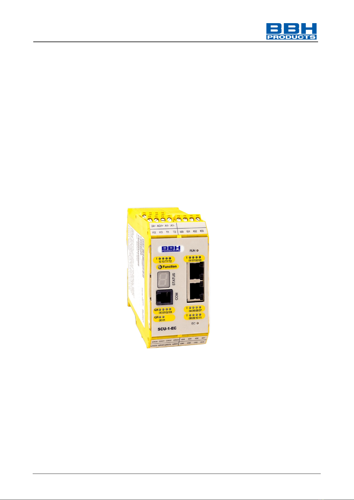
3.1. SCU unit
The SCU is a Master unit for FSoE communication to read encoder data and switching statuses of
external Slave units to implement safety functions.
The SCU can send, receive and process safe data via FSoE and unsafe data via EtherCAT. In the
EtherCAT network, the SCU only functions as Slave.
3.2. Network connection
3.2.1. EtherCAT
The EtherCAT network consists of one Master and a certain number of Slaves.
Data transfer is carried out via Ethernet connections existing between the EtherCAT Master and
every participant, and, as a rule, running serially from participant to participant. Via these
connections Ethernet-Frames are sent. Every network participant ´must first read the received
data, filter the data addressed to it, and insert the exit data into the Frame. Having passed all
Slaves, the Frame is sent back to the EtherCAT Master.
As thus every participant can influence the transfer of a message, the network must be exactly
defined or specified. This specification is carried out via the ESI files, fixing the participants and
their properties.
Data transfer is always initiated by the Master. –Data transfer is carried out in the EtherCAT
network with a transfer time of at best a few µs.
Figure 1: EtherCAT network
Master
In Out
In Out
Slave
In Out
Slave
In Out
Slave
In Out
Slave

Programming manual SCU-series
HB-37500-820-10-12F-EN SCU Programming manual Page 19 of 252
Status: 19.03.2021
3.2.1.1. EtherCAT data transfer
Basically, a difference is made between process data that must be transferred cyclically, and
acyclic data, such as configuration data and diagnostic data.
The cyclic process data are assigned to the PDOs (Process Data Objects).
Length and content of the PDOs can be either fixed or variable. The variable content is fixed by the
PDO mapping. The PDO’s possibilities are fixed by the individual participant’s description file (ESI
file).
Primarily, acyclic data services are SDOs (Service Data Objects), but they can also be EoE
(Ethernet over EtherCAT) or FoE (File over EtherCAT).Also here, the possibilities of the acyclic
services are fixed by the individual participant’s description file (ESI file).
3.2.2. FSoE
FSoE (Fail Safe over EtherCAT) is the safe data transfer via the EtherCAT network. User data are
compiled into data packages, and are supplemented with an additionally transferred checksum.
The transfer is carried out every 1ms.
Furthermore, the transfer is monitored via timer (Watchdog) which is checked in every network
participant. Thus, any interruption of the data transfer can be safely recognized.
The checksum is calculated with a CRC 16 (16-Bit-Cyclic Redundancy Check), and allows to
recognize a fault with a residual error probability of < 10-9 and thus allows a safe data transfer
suitable for the use up to PL e or SIL 3.
Among others, the following units are suitable as FSoE-Slaves:
•SSB = Safe Sensor Box Slave unit by BBH to read 6 axis
•SDU = Safe Drive Unit Slave unit by BBH to read one axis
•SIO = Safe IO Slave unit by BBH to read IOs
•EL 1904 Slave unit by Beckhoff (to read entries)
•EL 2904 Slave unit by Beckhoff (to switch outputs)
•AX 5805 Slave unit by Beckhoff (to read axis data)
•AX 5806 Slave unit by Beckhoff (to read axis data)
•SDC Slave unit by LT-i (to read axis data and IOs)
In general, also units manufactured by other companies can be incorporated as FSoE Slaves if
they offer an FSoE communication.
Programming manual SCU-series
HB-37500-820-10-12F-EN SCU Programming manual Page 20 of 252
Status: 19.03.2021
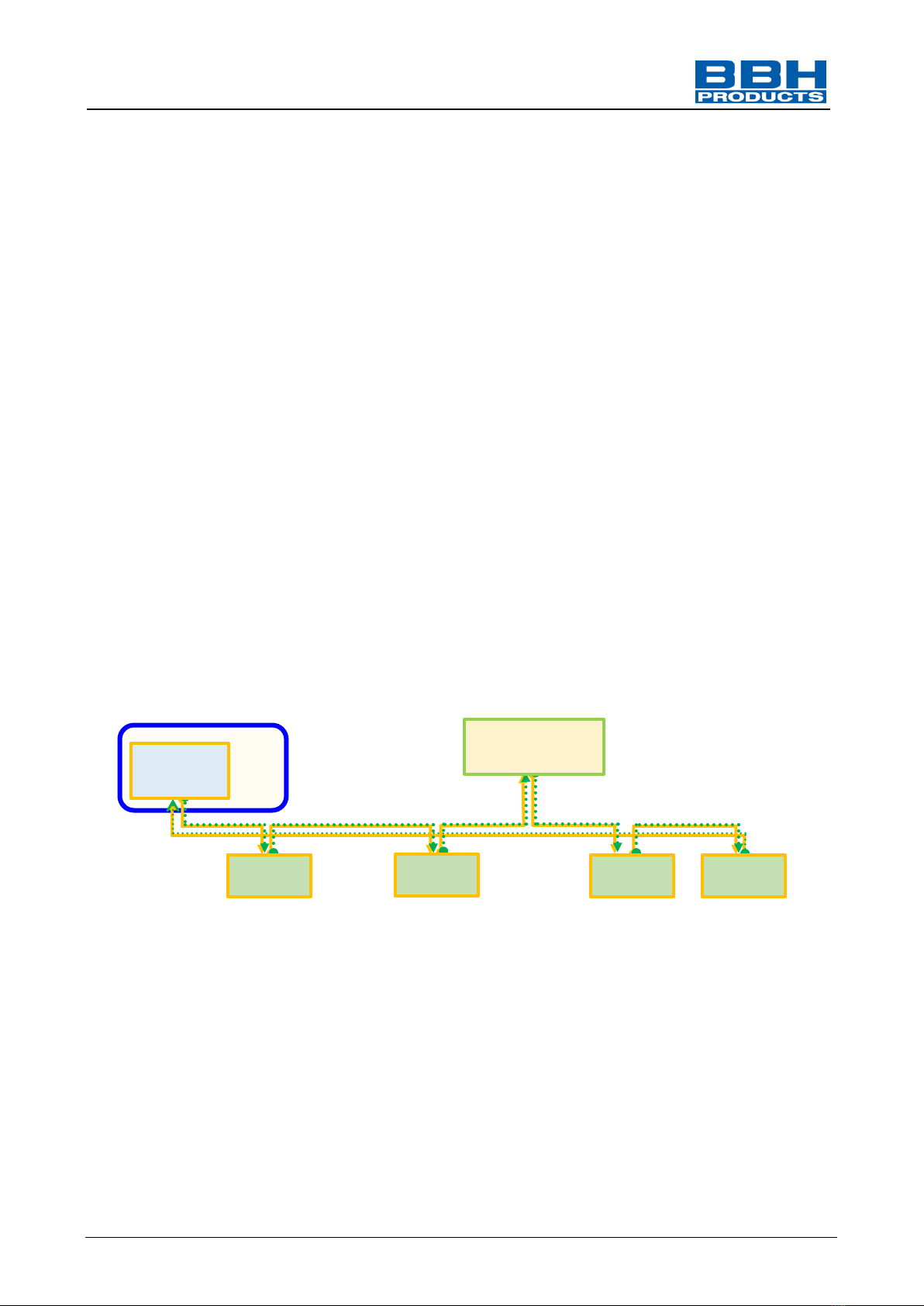
3.2.3. FSoE and EtherCAT
The Ethernet frame of the EtherCAT network can contain non-safe as well as safe data. The safe
data are called FSoE data, and are assigned to the FSoE Master-and-Slave protocol stack. These
data are transferred cyclically, and are thus included in the PDO of the respective participant.
The SCU is designed as FSoE Master, and it starts the safe data transfer via FSoE. Furthermore,
as EtherCAT Slave, the SCU participates in the non-safe EtherCAT network.
A separate EtherCAT Master starts the non-safe data transfer via EtherCAT.
The PDOs with the included FSoE files are transmitted cyclically. The cycle time of the transfer is
fixed in the configuration of the EtherCAT -Masters. As a rule, it should be adjusted many times
shorter than the cycle time of the FSoE master to grant the update of the data within the Watchdog
control time of the FSoE Master.
The SCU (FSoE Master) starts the safe data transfer via FSoE, receives from the Slave groups (e.
g. SIO, SDU, SSB) the data from inputs and evaluates these data. Afterwards, the SCU can
implement safety functions, and can switch outputs accordingly –this can be done either by the
proper outputs of the units, or by the outputs of the Slave units.
Furthermore, as EtherCAT Slave, the SCU is participant in the non-safe EtherCAT network.
A separate EtherCAT Master starts the non-safe transfer via EtherCAT.
S= Safe (Data Transfer) = FSoE
N= Non-safe (Data Transfer) = EtherCAT
S+N
N
SCU
EtherCAT-Master
In Out
In Out
Slave
In Out
Slave
In Out
Slave
In Out
Slave
FSoE-Master
In Out
S+N
S+N
S+N
N
Figure 2: FSoE network
Other manuals for SCU Series
1
Table of contents
Other BBH Measuring Instrument manuals

Popular Measuring Instrument manuals by other brands


PCB Piezotronics
PCB Piezotronics JM352C68 Installation and operating manual

BiOptic
BiOptic Qsep100 Operation Quick Start Guide

Muller Ziegler
Muller Ziegler DSMG 96 manual

OEG
OEG 310 821 216 instruction manual

Hanna Instruments
Hanna Instruments HI88713-01 instruction manual

Hach
Hach 59530-16 instruction manual


