ETCR 9000 User manual

Catalogue

- 1-
Warning…………………………………………………………………2
I. Profile…………………………………………………………………3
II. Electrical Symbols……..……………………………………………4
III. Technical Specifications...…………………………………………5
IV. Structure….…………………………………………………………7
V. LCD Display…………………………………………………………8
1. LCD Display Screen……………….………………………………8
2. Explanation for Special Symbols…………………………………8
3. Display Demonstration ……………………………………………8
VI. Operation Ways….….……………………………………………10
A. Tester Operation...………………………………………………10
1. Power On/Off ….…………………………………………………10
2. Gear Shift Choice …..……………………………………………11
3. General Test………………………………………………………11
4. PEAK Test …..……………………………………………………13
5. Data Maintenance ….……………………………………………14
6. Data Memory…..…………………………………………………14
7. Data Reference ….………………………………………………14
8. Data Deletion ….…………………………………………………14
*9. Data Transmission…..……………………………………………15
*B. Operation of Receiver …..………………………………………15
1. Power On/Off…..…………………………………………………15
2. Data Reception …..………………………………………………15
3. Data Maintenance ….……………………………………………16
4. Data Memory ….…………………………………………………16
5. Data Reference ….………………………………………………16
6. Data Deletion ….…………………………………………………16
VII. Replacing Batteries …..…………………………………………17
VIII. Packing List...……………………………………………………17
Enclosed with Tester Assembly Drawing ….………………………18
Warning

- 2-
Thanks for your purchase of ERCR9000 H/L Voltage Clamp
Meter of our company. In order to make better use of this product,
please make sure to:
----Read this manual in detail and the operator must totally
understand this manual and be in proficient in operation of this
meter before making test on spot.
----Comply strictly to the security rules and notice items listed
on this manual.
uIn any case, it should pay special attention to safety in use of
this meter, particularly in measurement of circuitry with more
than AC100V and above voltages.
uIf the voltage of tested circuitry has exceeded 600V, it must be
used by connecting with an insulation rod.
uAs it is very dangerous of high voltage transmission line, the
operator must get strict training and the relevant certification
on high-pressure operation of the state before using this meter
and making a field test.
uIt is strictly forbidden to use this meter to test the wire or
convergence generatrix without any insulation.
uPlease pay attention to marked words and symbols on panel
or backboard of this meter.
uPlease do not put or store this meter in the place of high
temperature, with moisture, with frozen dew or with direct
daylight irradiation for a long time.
uPlease note the battery polarity when replacing battery, and
remove the battery if do not use this meter for a long time.
uIt must be operated by qualified staff that has the authorization
on tearing down or repairing this meter.
uPlease do not use it when there is any damage on the
transducer clamp or other parts of this meter.
uTo avoid the impact of transducer clamp, it needs to maintain
this meter regularly. Do not use corrosive or coarse articles to
clean, but use soft cloth (such as glasses cloth), dipping clean

- 3-
anti-rust desiccant lubricant (such as WD-40), and making a
gentle wiping.
uFor the reason of this meter, in case that any danger may
occur if continue to use it, stop using it immediately and seal it
up for keeping at once, which shall be dealt with by qualified
authorization agency.
uThe danger symbol “ ”on the meter and the manual, the
user must make safe operation according to the indication.
uThe extremely dangerous symbol “ ”, the user must make
safe operation according to the indication.
uTo test unknown current, please choose “600A” level to test
firstly.
uIt suggests that this meter shall be made insulation intensity
test at least once annually. (AC40KV/rms between insulation
pole and clamp core.)
uAs to the part with “*”mark in this manual, it is only limited to
ETCR9000A (infrared transmission data type).
ProfileⅠ
ETCR9000 Series H/L Voltage Clamp Meter has broken
through the traditional structure, which is specially well-designed
for measuring high voltage current, adopting the latest CT
technology and integrated mask digital technology, formed by
composition of a special use clamp meter with a high-voltage
insulation rod, as to ETCR9000A type -- infrared transmission of
test data, also equipped with receivers, which can monitor the
tested data in a long distance on real-time. If not using an
insulation rod, it can be also used as a high precision low-voltage
clamp meter, or an alternating current meter, which can accurately
measure1mA of current or leakage current.
ETCR9000 Series H/L Voltage Clamp Meter has an innovative
integrated design between transducer clamp and transducer
domain, ensuring the high-precision, high-reliability, and

- 4-
high-stability on constant test perennially.
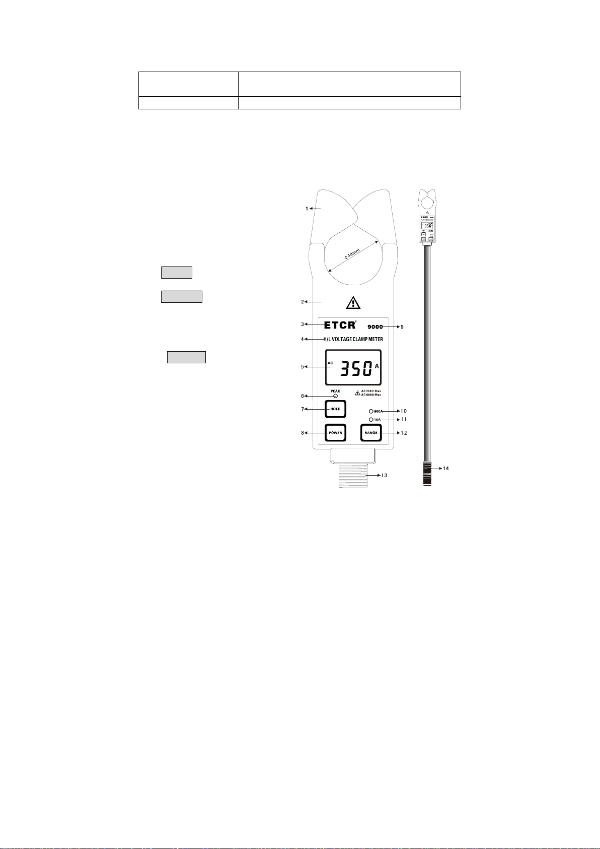
ETCR9000 Series H/L Voltage Clamp Meter is connected with
insulation rod, which can be used for measuring high voltage
current that is below 23KV, on-line current measurement, also
having peak maintenance, data preservation, data storage,
infrared transmission and other functions, and its special clamp
meter can make it easier for clamping or evacuating the tested wire
through pressing or pulling back the insulation rod, time-saving
and fast, widely used in transformer substation, power plant,
industrial and mining enterprises as well as the inspection station
and electrician maintenance departments for electrical current
detection and field electrical operations. It can also replace the H/L
voltage transforming ratio tester, that is, to detect the high and low
current for primary circuit and secondary circuit separately, and
then calculate to conclude the change of high and low pressure.
The insulation rod is light and convenient, with the advantages of
anti-moisture, high temperature resistance, anti-impact, bending
resistance, high insulation, flexibility and other characteristics.
ⅡElectrical Symbols
Extremely Dangerous! The operator must strictly
abide by the safety rules. Otherwise, there is electric
injury danger, causing personal damage or casualty
accident.
Dangerous! The operator must strictly abide by the
safety rules. Otherwise, there is electric injury
danger, causing personal damage or casualty
accident.
Warning! It must strictly abide by the safety rules.
Otherwise, it may cause personal damage or
casualty accident.
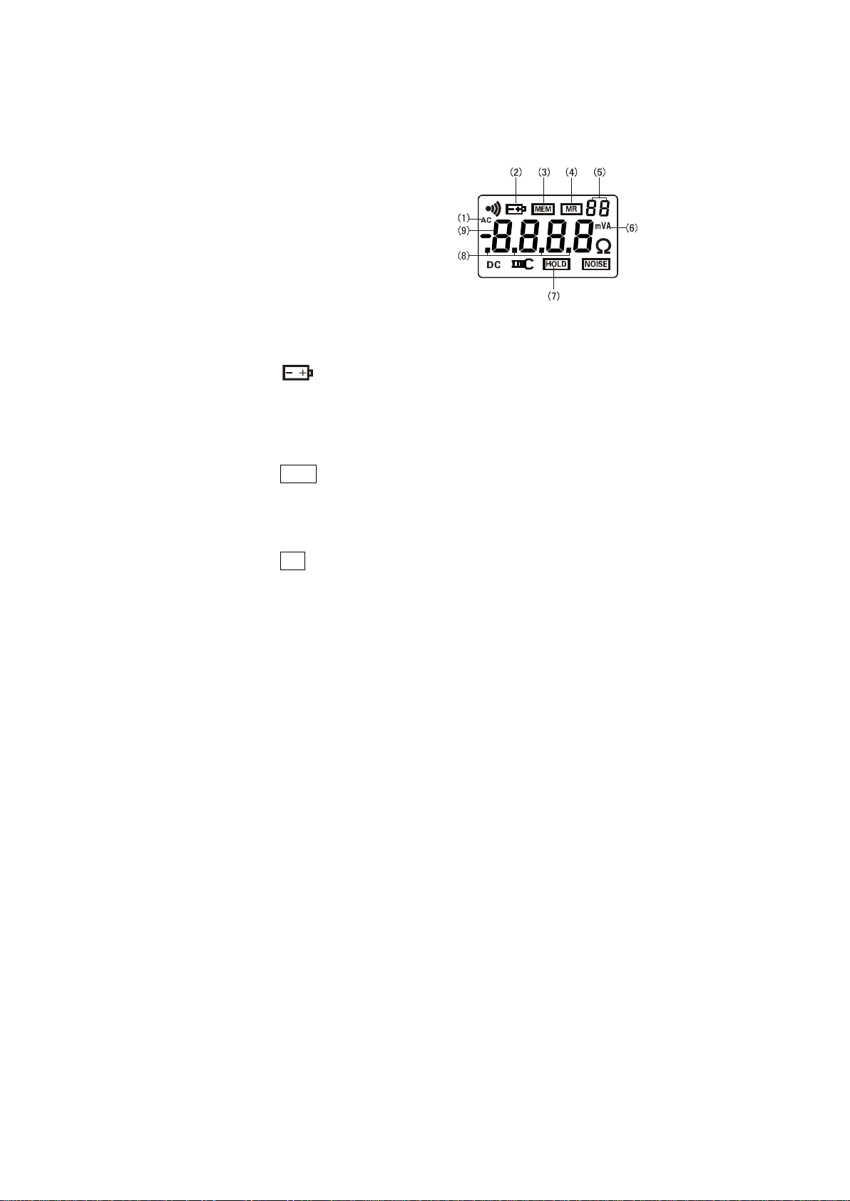
Alternating Current (AC)
Direct Current (DC)

- 5-
III Technical Specifications
Function High voltage AC current measurement, low
voltage AC current, leakage current
measurement, on-line AC current supervision.
Power Supply
DC6V Alkaline Dry Battery (1.5V AAA X 4)
Test Method
Clamp CT, Integral Method
*
Transmission
Method Infrared Transmission, the maximum distance
for direct transmission is about 10m.
Display Mode 4 digital LCD display, backlight function,
suitable for dark place.
LCD
Dimension 47mm x 28.5mm
Meter Dimension
W/H/T: 76mm×255mm×31mm
Clamp Diameter
φ48mm
Sampling Speed
Around 2 times/second
Measurement
Scope 1mA~600A(50/60HzAuto Identification)
Resolution Rate
1mA
Measurement
Range
10A/600A, Double measurement ranges can
be switched by manual, and it can be
transferred automatically within each
measurement range.
Test Precision
(23 ±5℃ ℃ ,
Below 80%RH)
1mA~299mA: ±1%±3dgt
300mA~10.00A: ±1.5%±5dgt
0.0A~49.9A: ±1.5%±5dgt
50.0A~199.9A: ±2%±5dgt
200A~399A: ±2.5%±5dgt
400A~600A: ±3%±5dgt
Circuit Voltage Test for the circuit below 23KV (operated with
insulation rod)

- 6-
Technical Specifications (Continued Table)
Data Memory 99 Groups, during storage, the symbol “MEM”
gives indication, “FULL” mark will flash to
indicate the memory has been full.
Peak
Maintenance
The function of automatic capture and
maintain the maximum average value, under
general test mode, press HOLD button longer
till PEAK light is bright, that is, start PEAK test
function, also known as peak test.
Data
Preservation Under general test mode, press HOLD button
to preserve data, “HOLD” symbol display.
Data Reference “MR” symbol indicates, it can read the stored
data by turning upwards and downwards.
Overflow
Display Exceed measurement range overflow
function: “OL A” symbol display
*
No
signal
Indicator When the receiver has not received transmit
signal, it will display “no- -”signal dynamically.
Auto Shut Down
In about 15 minutes after booting, the meter
will shut down automatically, in order to
decrease the battery consumption.
Battery Voltage When the battery voltage is below 4.8V, the
symbol of battery voltage “ ”will show to
remind to replace battery.
Meter Quality Tester: About 335g (Including battery), total
quality of meter: about 2.5Kg (including
insulation rod and battery.)
Work
Temperature and
Moisture -10℃~40℃;Below 80%Rh
Storage
Temperature and
Moisture -10℃~60℃;Below 70%Rh
Insulation Rod
Dimension φ32mm,1m/Section(5 Sections)

- 7
Technical Specifications (Continued Table)
Insulation
Intension AC 40KV/rms (Between insulation rod and
clamp core)
Str
ucture
Anti-Dripping Type II
ⅣStructure
1. Transducer clamp
(including transducer domain)
2. Tester
3. Brand Sign
4. Product Name
5. LCD Display
6. Peak Test Mode Indicator
7. HOLD Key
(Key Combination)
8. POWER Key
(Key Combination)
9. Product Type
10. 600A Level Indicator
11. 10A Level Indicator
12. RANGE Measurement
Range Switch Key
13. Insulation Rod Connector
14. Handle

- 8-
ⅤLCD Display
1. LCD Display Screen
⑴. AC Symbol
⑵. Symbol for low
battery voltage
.⑶Data Storage Symbol
.⑷Data Reference Symbol
.⑸2-digit Storage Data
Serial Number
.⑹Unit Symbol
.⑺Data Locked Symbol
.⑻Decimal System Radix Point
.⑼4-Digit LCD Digital Display
2.Explanation for Special Symbols
.⑴Symbol for low battery voltage. When the battery
voltage is lower than 4.8V, this symbol will show.
Please replace battery in time.
.⑵This symbol “OL A” denotes that the current on test has
exceeded the maximum measurement limit of the
meter.
.⑶“MEM” Memory Mode, it will show during the storage
process of the data.
.⑷“FULL” Symbol, when the memory data has been filled
with 99 groups, it will show “FULL” symbol by flash,
which means it cannot continue to store data.
.⑸“MR” data reference symbol, which is shown during
referring to data, meanwhile, it will show the serial
number of data in storage.
.⑹“End” exit symbol, it will show during sign out.
.⑺“dEL” data delete symbol, it will show during deleting.
* .⑻“no- -”no reception signal indicator, dynamic display. It
is possible that tester has not been placed in test mode.
3.Display Demonstration
.⑴——The current on test is: 0.002A (2mA)

- 9-
.⑵——Lock Display Data
——This data is automatically stored in Group 3
——The current on test is: 160.5A
.⑶——The current on test is: 571A
——Display symbol for low battery voltage.
Please replace battery.
.⑷——Refer to data of group 3 in storage
——The current on test is: 160.5A
.⑸——“FULL” flash display:
Memory are full of 99 groups
——It cannot store more unless delete the memory
.⑹——Data Delete Indicator “dEL”

- 10-
.⑺——Exit Function Indicator “End”
* .⑻——“no- -”dynamic display:
No reception signal
ⅥOperation Ways
Please check all parts of the meter carefully
before usage to see whether there is any damage.
And make sure no damage before usage.
To install battery according to the illustration of this
manual.
A. Tester Operation
1.Power On/Off
Press POWER button for power on, LCD display, entering
normal test mode. If LCD display is relatively dark after power
on, it is possible that battery voltage is a bit lower. Please
replace battery. In 15 minutes after power on of the meter,
LCD will continue flashing to give hint for automatic power off,
after 30 minutes for continuous flash of LCD, it will shut down
automatically, in order to lower the battery consumption. In
case of LCD continuous flash, press POWER button, then the
meter will continue to work.
Under HOLD mode, press POWER button for power off.
Under general test mode, press POWER button for

power off.
Under PEAK test mode, firstly press POWER button for
exit from PEAK test mode, returning to general test mode,
then press POWER button for power off. That is, under PEAK
test mode, it needs to press POWER button twice for power
off. Under data reference mode, firstly press POWER button
longer (over 3 seconds) for exit from data reference mode,
returning to general test mode, then press POWER button for
power off. During the exit from data reference, it will show
“End” symbol.
2.Gear Shift Choice
Only under test mode, it is available for gear choice.
Gear choice button RANGE is self-lock button, so it
needs to press a bit heavier.
Press RANGE button to choose 10A or 600A level, and
the relevant indicator light will light. If the current on test is
unknown, please choose 600A level firstly, and then make the
most suitable gear level according to the test result.
Under data reference mode, both gear shift indicator and
PEAK light are not bright.
3.General Test
High voltage, extremely dangerous! It must be
operated by qualified staff that has acquired
authority. The operator must strictly abide by the
safety rules. Otherwise, there is electric injury
danger, causing personal damage or casualty
accident.
Dangerous! It cannot be used to measure the
circuit over 23KV voltage. Otherwise, there is
electric injury danger, causing personal damage
or equipment damage.
Dangerous! It cannot be used to measure the
circuit over 600A voltage. Otherwise, there is
electric injury danger, causing personal damage
or equipment damage.

- 11 -
General Test: In the process of test, it will show the tested
current value on real time by LCD display, and LCD data will
vary with the current change. When the tester is removed
away from the lead on test, it will not preserve the test result,
LCD display will return to zero.
In general test mode, it is suitable for close distance
measurement, convenient for circuit test by direct read of LCD
data.
(
*
Special note: ETCR9000A type adopts infrared
transmission of test data, which has no limit for read
display data on receiver. The display date on receiver are
totally the same with display emission data of tester, so it
is very straight no matter in which test way by using
ETCR9000A type.)
Before test, firstly to connect insulation rod, which
must be connected in right position, and then to
connect tester, avoiding the impact of meter to
ground surface.
Make sure to use specially equipped insulation
rod to connect with the meter.
After test, it should incline the insulation rod
accordingly on drawing in. Firstly to tear down the
tester and then the insulation rod, avoiding the
impact of meter to ground surface.
After normal boot, place the lead in the middle of clamp
transducer domain, as shown in Figure A, with the meter
transducer domain perpendicular to the lead, pushing the
meter forwards to clamp the lead on test, showing the result
on LCD display. If showing "OL A", it means the lead current
on test has exceeded the maximum volume on the level.
Please select a higher gear level or a meter with greater
measurement limit.
To pull backwards can make the meter remove from the
lead on teat, as shown in Figure C, on removing, please try to
keep the meter transducer domain perpendicular to the lead.

- 12-
Under HOLD mode, press HOLD button to cancel HOLD
function, and return to general test mode.
Under data reference mode, press POWER button longer
(over 3 seconds) to exit from data reference mode, returning to
general test mode.
Under PEAK test mode, press POWER button for exit
from PEAK test mode, returning to general test mode.
After data deletion, it will return to general test mode
automatically.
Attention! For the sake of safety, on testing
strong current, as long as the correct operation
test has been finished on confirmation, please
remove the meter away from the lead on test.
4.PEAK Test
PEAK Test: Peak Test. In the process of test, the meter will
make automatic comparison on the changes in measured
current, indicating the maximum average value and maintain it,
when the meter is removed away from the lead on test, the test
result will be kept consistently, suitable for the circuit test on
those LCD data hard to be read directly.

- 13 -
Under general test mode, press HOLD button longer (over
3 seconds), PEAK indicator light will be bright, entering PEAK
test mode. That means meter will show and automatically keep
the maximum average value in the test.
Under any other mode, it must be returned to general test
mode, and then make PEAK test according to the above
operation.
Press POWER button to exit from PEAK test mode,
returning to general test mode, and it will display “End” symbol
during the exit.
5.Data Maintenance
Under general test mode, press HOLD button shortly to
keep LCD display, “HOLD” symbol shows. Press HOLD button
shortly again for release of data lock, returning to general test
mode, and HOLD” symbol disappears.
6.Data Memory
Under general test mode, press HOLD button to maintain
data, meanwhile, the meter will automatically form serial
numbers, and memory the current preserved data. During the
storage, “MEM” symbol will show once by flash. This meter
can memory 99 groups of data, in case of full storage, “FULL”
symbol will show by flash continuously, and it cannot continue
to memory until cleaning out the previous memory.
7.Data Reference
Under general test mode, press HOLD button + POWER
button to enter data reference mode, showing “MR” symbol,
meanwhile, it will automatically display data saved in the group
1. Then press HOLD button or POWER button to read the
stored data by turning upwards or downwards in cycle. It will
return to the group 1’s data automatically after reaching the last
group’s data in storage.
Press POWER button longer (over 3 seconds) to exit from
data reference mode, returning to general test mode. During
the exit, it will show “End” symbol.
8.Data Deletion

- 14 -
Under data reference mode, press HOLD button +
POWER button to delete all the data in storage, and return to
general test mode. During the deletion of data, it will show
“dEL” symbol.
*9.Data Transmission
ERCR9000A TYPE has the function of infrared data
transmission. When the meter is under test mode, the test
result will be transferred to receiver through infrared
transmission, and the receiver will show the test result on
real-time, being clear at a glance.
Only under test mode, can it launch infrared data. If the
receiver has not received emission signals, it will show “no - -”
symbol dynamically.
The maximum distance for ERCR9000A type data
emission and reception is the about 10m. However, with the
decreasing of the battery voltage, the reception distance will
gradually shorten. In case that the battery voltage is badly
insufficient, it is possible to have no way to receive data.
(When the battery voltage is 5V, the reception distance is about
7m).
* B. Operation of Receiver
1.Power On/Off
Press POWER button for power on, LCD display, entering
receiving data mode. If LCD display is relatively dark after
power on, it is possible that battery voltage is a bit lower.
Please replace battery. In 15 minutes after power on of the
receiver, LCD will continue flashing to give hint for being
power off, after 30 seconds for continuous flash of LCD, it will
shut down automatically, in order to lower the battery
consumption. In case of LCD continuous flash, press POWER
button, then the receiver will continue to work.
Under HOLD mode, press POWER button for power off.
Under data reference mode, firstly press POWER button
longer (over 3 seconds) for exit from data reference mode,

- 15-
returning to receiving data mode, then press POWER button
for power off. During the exit from data reference, it will show
“End” symbol.
2.Data Reception
After normal power on, the receiver will under receiving
mode. If there are emission data, the receiver will show the
test result on real time. If it has not received any signal, the
receiver will search signals constantly, and show “no - -”
symbol dynamically.
3.Data Maintenance
Under receiving data mode, press HOLD button shortly to
keep LCD display, “HOLD” symbol shows. Press HOLD button
shortly again for release of data lock, returning to receiving
data mode, and HOLD” symbol disappears.
4.Data Memory
Under receiving data mode, press HOLD button to
maintain data, meanwhile, the receiver will automatically form
serial numbers, and memory the current preserved data.
During the storage, “MEM” symbol will show once by flash.
This receiver can memory 99 groups of data, in case of full
storage, “FULL” symbol will show by flash continuously, and it
cannot continue to memory until cleaning out the previous
memory.
5.Data Reference
Under receiving data mode, press HOLD button +
POWER button to enter data reference mode, showing “MR”
symbol, meanwhile, it will automatically display data saved in
the group 1. Then press HOLD button or POWER button to
read the stored data by turning upwards or downwards in cycle.
It will return to the group 1’s data automatically after reaching
the last group’s data in storage.
Press POWER button longer (over 3 seconds) to exit from
data reference mode, returning to receiving data mode. During
the exit, it will show “End” symbol.

- 16-
6.Data Deletion
Under data reference mode, press HOLD button +
POWER button to delete all the data in storage, and return to
receiving data mode. During the deletion of data, it will show
“dEL” symbol.
ⅦReplacing Batteries
Warning! In case that the battery’s cover
board is not well closed, it is forbidden to
make test. Otherwise, it is dangerous.
Pay attention to the polarity of battery, in case
of damage to the meter.
Do not mix in the use of new and old batteries.
1. When the battery voltage is below 4.8V, the meter will show
“ ”symbol, indicating the batteries have no sufficient
power content. Please replace batteries.
2. Power off, to make sure the meter is under the state of
power off. To loosen two screws of the battery cover board,
open the cover board to replace brand-new qualified
batteries on. It should pay special attention on the battery
specification and polarity, cover the board well and fasten
the two screws.
3. Press POWER button to
check whether the meter
can be powered on
normally. If not, please
repeat the operation
according the step 2.
Ⅷ Packing List

-17 -
Tester 1PCS
*
Receiver 1PCS
Insulation Rod (1M/Section) 5 Sections
Meter Box
1PCS
Battery (Alkaline Dry BatteryAAA) 4 PCS(* or 8 PCS)
User’s Manual/ Maintenance Card/
Conformity Certificate 1SET
Enclosed with Tester Assembly Drawing

- 18-
Guangzhou City Yitai Electronics Technology Co., Ltd.
Address: 3rd Building B, Xianbei Industry Zone, Beiji, Baiyun Road,
Guangzhou City.
Postal Code: 510440
Tel.: 86-20-36282512 36282505
Fax.: 020-36282515
Website: http://www.etcr.cc
This manual suits for next models
5
Table of contents
Other ETCR Measuring Instrument manuals