WWW.BBKPERFORMANCE.COM
FOLLOW THESE INSTRUCTIONS CAREFULLY TO ENSURE CORRECT FITMENT AND OPERATION
UPDATED LAST: April 2018
27427 BOSTIK COURT
TEMECULA, CA 92590
For any questions, email us:
IMPORTANT: All appropriate safety equipment and gear must be used during the installation of this or any BBK Performance products or any time you work on a vehicle.
BBK Performance Inc. accepts no responsibility for injuries or damage caused by or during the installation of this product.
MADE IN U.S.A.
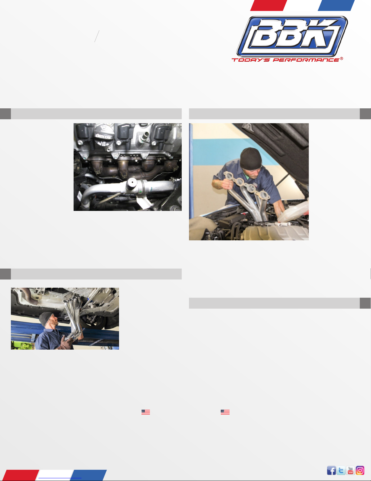
STEP 16
With both head pipes in place lift the exhaust system upwards and connect
the head pipes to the collector on the headers only snug the bolts up. Be
sure to level out the exhaust and adjust it to have clearance. Push the exhaust
system forward as much as possible while still having clearance everywhere.
Tack weld the BBK head pipes to the stock exhaust once tacked into place
check for any clearance issues and address them immediately. Now weld the
lower portion of the head pipes to the stock exhaust completely once both
sides are done unbolt the exhaust from the headers and drop it down and
nish welding the head pipes to the stock exhaust system.
Lift exhaust system into place and tighten down the anges on the head pipes
to the anges on the header collectors these bolts do not have to be crazy
tight as it may result in bending of the anges.
STEP 17
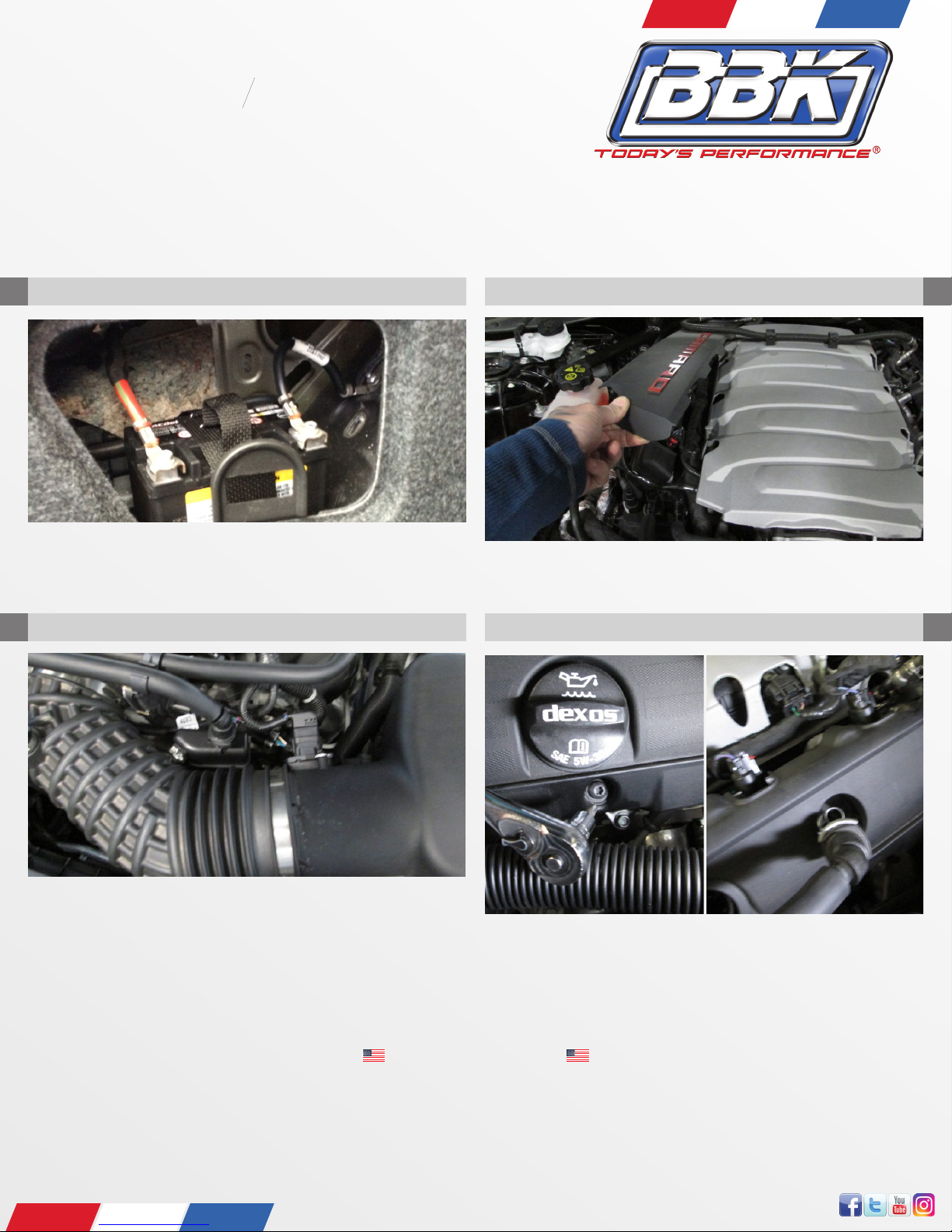
Install all (4) oxygen
sensors and connect
the wiring harnesses.
Reconnect the
negative battery
terminal and enjoy
the sound and power
of the BBK full length
headers “REMINDER”
check coolant levels
after start up and
engine is at operating temperature if any coolant was lost. After 500 miles
of driving re-torque all exhaust hardware to ensure the exhaust system is
properly sealed.
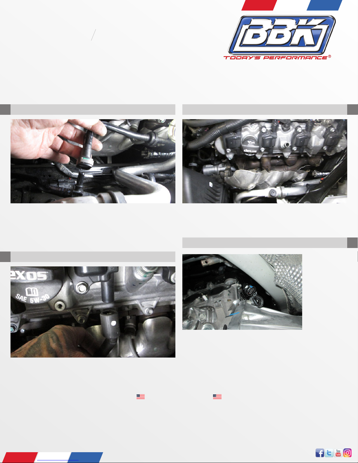
for added clearance. Now install header with supplied
gasket then install dipstick when header is loose in engine compartment. Now
torque header bolts to 30 FT/LB then reinstall,valve cover,spark plugs, wires
and then starter heat-shield from underneath the vehicle when installing
head-pipes. Now re-connect radiator hoses and put coolant bottle back in
place
NOTE: Make sure to check coolant level and use remaining zip-ties to keep
any hoses from resting on header and do not over tighten zip-ties cutting o
coolant ow.
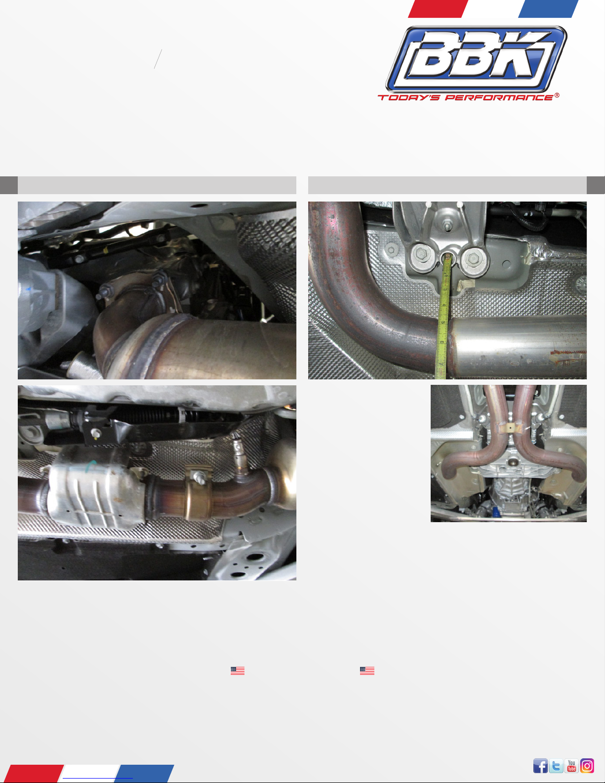
STEP 15
Head pipe adapter installation there is a driver and passenger side head pipe.
The driver side head pipe is the longer of the (2). Install the supplied hardware
studs into the anges on the BBK full length headers. Slide the end of the head
pipe over the stock exhaust pipe where it was cut o in (step 11.) 0nce in place
rotate the head pipe so that the oxygen sensor bung is facing towards the
center of the car. Repeat this step for the passenger side.
Cont. step 14.
NOTE! ON MANUAL TRANSMISSION CARS YOU WILL NOT NEED 02 SENSOR EXTENSION AS FACTORY HARNESS
EXTENDS TO CORRECT LENGTH. FOR AUTOMATICS YOU WILL NEED TO PURCHASE DR-SD EXTENSIONS
!