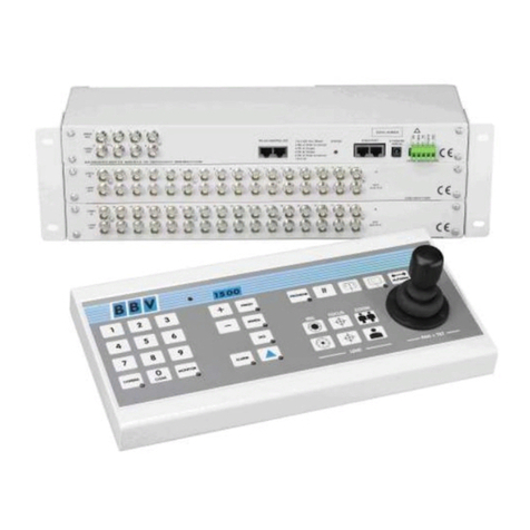
BBV FBM User manual

Versions 1.64 and beyond
Installation Guide
FBM Video Matrix
BBV
For quick setup of the FBM, a video tutorial can be found on the online FBM
Information Console. Please read pages 18, 19 and 24 of the manual for details.


STOP AND READ
BEFORE INSTALLING!
As 3rd party protocols are not under the control of BBV,
we cannot guarantee that this unit will provide the exact
functionality required.
It is strongly recommended that operation is confirmed
during prebuild testing before installing on site.
Please contact our customer support department
if you have any questions/issues:
Tel: ++ 44 (0) 1323 842727
Email: support@bbvcctv.com
DISCLAIMER:
BBV are not liable for any errors within this manual. If you nd an error,
please let us know immediately.

Scan for a quick tour of the BBV website:
www.bbvcctv.com

Contents
After connecting to the system described on pages 18 and 19, navigate to the tutorials
on the info page by pressing the System button and then the Information button.
Pre-Installation checks and procedures 6
Technical Specification 7
Which Version Do I Have? 8
Matrix Setup
(gure 1)
9
Setup 10 - 11
Setup - Order of Installation 10
Step by Step Guide 10-11
System Component Details 12 - 16
FBM CPU 12
System setup 13
Keyboard connection details 13
Connecting Alarm Cards 14
BBV Starcard - daisy chain telemetry 14
BBV Starcard - star wired telemetry 15
19U Matrix Setup 16
Tx1500/KBD - system keyboard 17
FBM Information Console 18 - 32
Getting Started 18-19
Login 20
Status 21
System 22
System > Conguration 23
System > Tutorials 24
Alarm Status 25
Alarms 26
Alarm Settings 27
Logging 28-29
Cameras and Control Telemetry 30
Cameras 31
Control 32
Monitors 33
Restart 34
Keyboards 35
Defaults 36
Maps 37-38
Alarm Card Setup 39 - 41
Alarm Card Setup 39
Alarm input card 40
Alarm Card Relays 41
Backup FBM Settings 42
Restore FBM Settings 43
Access Dome Menu 44
Example Setups 45 - 49
BBV Product List 50 - 51

6
Pre-Installation checks and procedures
Unpacking
Check packaging – Upon delivery of the unit, inspect the packaging for signs of damage. If damage has occurred, inform the
carrier and or the suppliers immediately.
Check Contents – After unpacking, check that all items are present. If any items are missing or damaged, contact the
equipment supplier.
Important Safety Precautions
Read Instructions – All relevant safety, installation and operating instructions should be read before attempting to install,
connect or operate the unit.
Retain Instructions – All safety, installation and operating instructions should be retained for future reference.
Heed Warnings - All warnings on the unit and in any relevant safety, installation or operating instructions should be
adhered to.
Cleaning - Switch off and unplug the unit from the power outlet before cleaning. Do not use liquid cleaners or aerosol
cleaners. Use a damp cloth for cleaning.
Attachments – Do not use attachments which are not recommended by the product manufacturers as they may cause a
hazard or damage the unit.
Water and Moisture - Do not expose this unit to water or damp.
Installation and mounting – Only install the unit in a suitable enclosure or mount.
Power Sources – This unit should only be operated from the type of power source indicated in the manufacturer’s label. If
you are not sure of the type of power supply you intend to use, consult your equipment dealer or local power company. For
units intended to operate from battery power or other sources, refer to operating instructions.
Object and liquid entry – Never push objects of any kind into the unit, as they may touch dangerous voltage points or short
out parts that could result in re or electric shock. Never spill liquid of any kind on or inside the unit.
Servicing – Servicing of the unit should only be undertaken by qualied service personnel, as opening or removing covers
may expose you to dangerous voltages or other hazards.
Damage Requiring Service – Servicing by qualied personnel should be carried out under the following conditions:
(a) When the power supply cord or plug is damaged.
(b) If liquid has been spilled, or objects have fallen into the unit.
(c) If the unit does not operate normally by following the operating instructions.
(d) If the unit has been dropped or the enclosure is damaged.
(e) If the unit indicates a distinct change in performance.
Replacement Parts – If replacement parts are required, ensure that only replacement parts recommended by the product
manufacturer are used.
Safety Check – Upon completion of any service or repairs to the unit, safety checks should be performed to ensure that the
unit is in proper operating condition.
Coax Grounding – If an outside cable system is connected to the unit, be sure the cable system is properly grounded.
Adhere to safety standards – All normal safety precautions as laid down by British Standards and the Health and Safety at
Work Act should be observed.

7
Technical Specification
Power Requirements 12Vdc 7.5A FBM matrix
Inputs 512 (larger by arrangement) Camera inputs per matrix*
Outputs 16 – 64 monitor outputs per matrix*
Telemetry PELCO D @ 9600 N 8 1** (this protocol is available on our support website
www.support.bbvcctv.com)
Items included:
• 1 x FBM Video Matrix (including 19 inch rack mounting ears) - with 3 slots.
• Matrix Switch & CPU
• 12Vdc PSU 7.5A - for FBM monitor
• Monitor Assy & PSU & F8
• Manual
• Quick Setup Guide
• Operation Guide
• 1 x Cat5 cable (Blue)
• 1 x Cat5 cable (White)
• TX1500 system keypad
• Metal Ears
• Metal Screws For Ears
• M4 Screws For Monitor
• USB Stick for system backup
* Please contact BBV Technical Support (support@bbvcctv.com) for conguration options
** Third party telemetry protocols are supported by the FBM matrix if a BBV Starcard Converter is used and other products,
please contact BBV Technical support for a complete list of supported protocols or visit our website. www.bbvcctv.com
Description
The FBM is a video matrix and telemetry control system offering control of up to 512 cameras from up to 16 control / operator
positions and is capable of supporting up to 64 monitor outputs. PELCO-D telemetry is employed as the standard protocol
with optional baudrates of 2400/4800 or 9600. This will provide control for most CCTV domes/cameras. Other RS485 / RS422
protocols are supported if a BBV Starcard Converter is used. Up-the-coax telemetry can also be supported by the inclusion
of a Coax Telemetry Interface (CTI Card) in the system design.
In order to simplify RS422 site wiring, a BBV Starcard should be used. This will provide 8 x RS422 telemetry ports, each port
will support up to 32 cameras. The inclusion of a BBV Starcard in the system design also provides a degree of fault tolerance,
for example if a cable connected to a telemetry port should fail, control of the cameras connected to that port only will be
affected, all other cameras connected to the system should continue to operate as normal.
Manual Version Software Version Release Date
6.96 1.64 12.11.18

8
Which Version Do You Have?
The diagrams and setup information throughout the manual are for Version 1.63 and current hardware. If you have an earlier
version, setup may differ. Please view the following diagrams to determine which version you have before continuing.
Earlier
Pre June 2018
Current
Released June 2018
USB cables need to be tted.
Keyboards require power and
data from Port 4.
No external USB cables.
Dedicated keyboard ports.

9
TX1500 Keyboard
FBM CPU
Alarm Card
10U Matrix Setup
(figure 1)
12V 7.5A
Cable Connection
Cat 5 CPU > Monitor
Cat 5 Keypad power port (orange area) > Keypad 1
Cat 5 (Optional) Port B > Alarm
Please Note:
This setup is specically for version 1.63 and beyond of the FBM (including any FBM system created from June 2018
onwards). For earlier versions, you will require a previous manual and may need additional equipment for setup. Please
contact BBV to discuss the additional elements you will require.

10
Connecting the HDMI monitor
1. Plug-in HDMI lead from FBM into monitor.
2. Plug in power into HDMI monitor.
3. The monitor can be either freestanding or mounted
onto the back of FBM.
Setup - Order of Install
Unpack
Connect HDMI Monitor
Connect 1 keypad (supplied) to any of the powered key ports
Connect video to input 1
Connect monitor to output 1
Power ON the FBM, FBM Monitor and relevant peripherals
- Wait for the system to boot.
Connect to matrix WIFI with computer
Use web page interface to setup system settings
Check PTZ control with keypad
Connect remaining video sources
Connect monitors & extra keypads
If you have alarms, connect Alarm Cards
1
2
3
4
5
6
7
A
HDMI monitor setup
1. Power ON
2. Press ‘AUTO’ button
3. Select HDMI
4. Use +/- key to save setting
C
Wait for system screen on the monitor
(As shown in the photo on the right).
D
Step by Step Guide
This step-by-step guide can be used in conjunction with ‘gure 1’ on the previous page.
8
9
10
11
12
Make relevant connections as shown
on previous page (figure 1)
1. Connect power to the matrix, the monitor and any
relevant peripherals.
2. Connect one keypad, then set keyboard addresses (p16).
B

11
Connect to matrix WIFI network with computer
(see full guide on page 18)
1. Connect to Network name: BBV_AP
2. Enter Password: BBVCCTV (password can be
changed later. See page 23)
3. Enter IP address in browser (for web page): 192.168.42.1
E
Check System Status on computer web page
1. Check that the FBM is running.
2. Check that the Keyboard, Alarm Cards and all other peripherals have
been detected.
F
Verify / Enter system settings
(see full gui on page 22)
1. Check/change the values in this section to suit your specic setup.
2. Fill-in the 4 highlighted elds, as seen in the diagram below
(e.g. for a system with 1 keypad, 128 cameras, 16
monitors and 1 Alarm Card; ‘Max Keyboards’ is 1, ‘Max Cameras’ is 128, ‘Max Monitors’ is 16, ‘Max Alarms’ is 16).
3. Once you’re happy with your System Settings, click the ‘Save’ button.
4. Once you’ve setup and saved the settings in each section, click the ‘Save and Restart’ menu tab at the top of the
web page. Then allow the FBM to reboot with the new settings.
H
Check and ll-in these elds
If you need to connect/setup Alarm Cards,
please see page 39
G

12
Basic FBM CPU
The CPU is the main controller for the system, for which the connector details are shown below:
CPU 4
Network 10 / 100 Port 192.168.0.63 Interconnection with Matrix Switch
WIFI Access Point BBV_AP 192.168.42.1 Password: BBVCCTV111
BBV Quad USB to Serial Interfaces
Network USB2 Interconnection with the CPU
Com A Keypad or BBUS interface addresses 0 to 7 (keypads 1 to 8)
Com B Alarms 1 - 128
Com C Telemetry Port (Pelco-D 9600 8 N 1)
Com D Telemetry Port (Pelco-D 9600 8 N 1)
Port E Key 9-16
Port F Alarms 129 - 255
Port G Telemetry
Port H Telemetry
Alarms
USB
System Component Details
Alarm
Telemetry 3 Telemetry 4
Telemetry 1
Telemetry 2
RJ45 Telemetry Connections (Blue Pair)
Tx+ Blue
Tx- Blue & White
Keypads 1-8
Keypad
4x powered keypad ports
Daisy chain port
Keypads 9-16
POWERED KEYPAD 422 PORTS
4 Ports for keypads which mirror Port A, with power. Good for 100 metres of Cat5 cable. Make sure the keypads are
addressed correctly (see page 17).

13
System setup
Starcard Converter
(Optional)
Starcard Converter
(Optional)
Extra Keyboard connection details
Figure 6 below shows a typical keyboard arrangement. The FBM
is capable of supporting up to 16 individual keyboards.
5
6
7
8
4
3
2
1
RED
BLACK
ORANGE
GREEN
YELLOW
BROWN
WHITE
Not Connected
+ 9 -12V DC SUPPLY
RXA (TO CPU)
TXA (FROM CPU)TXB (FROM CPU)
RXB (TO CPU)
0V SUPPLY
Not Connected
BB1 RJ45 Breakout box
BLUE
5
6
7
8
4
3
2
1
RED
BLACK
ORANGE
GREEN
YELLOW
BROWN
EULBETIHW
5
6
7
8
4
3
2
1
RED
BLACK
ORANGE
GREEN 5
YELLOW 6
BROWN 7
EULB8ETIHW
5
6
7
8
4
3
2
1
RED
BLACK
ORANGE
GREEN
YELLOW
BROWN
EULBETIHW
5
6
7
8
4
3
2
1
RED
BLACK
ORANGE
GREEN
YELLOW
BROWN
EULBETIHW
Keypad 1 Address 1 Keypad 2 Address 2
RS422 Termination onRS422 Termination off
Keypad Address
RS422 Termination OFF
Keypad Address
RS422 Termination ON
Upto 4 keypads. Direct connection.
Up to 8 keypads on chain

14
RJ45 Telemetry Connections
(Blue Pair)
Tx+ Blue
Tx- Blue & White
Connecting Alarm Cards
Alarm Card
Alarm Card
Alarm Card
12V 1A
12V 1A
12V 1A
BBV Starcard - daisy chain telemetry
A BBV Starcard will normally be required in a system where telemetry is employed. Usually it will not be feasible to wire the
telemetry in a daisy chain fashion, see examples below:
Figure 3. Direct Daisy chain telemetry wiring example
As can be seen from Figure 3, direct daisy chained telemetry is not a practical solution. The cable lengths can rapidly become
excessive (maximum allowable cable length = 1200m) and the labour cost to implement this option will be signicant. A much
better solution is shown in gure 4 below which shows the same system wired utilising a star card.
Keypad 1
Keypad connection

15
Figure 4. Star wired telemetry example
BBV Starcard Converter
This device offers the same connectivity options as the BBV Starcard, but in addition, performs a protocol conversion to allow
third party domes and telemetry receivers to be used with an FBM system. Only one protocol can be supported on each BBV
Starcard converter. The protocols are selectable via the built-in screen menu. Please refer to the BBV Starcard manual for
available protocol options.
BBV Starcard - star wired telemetry
PTZ
Address 1
Terminated
Address 2
Un-terminated
Address 3
Terminated
Address 5
Un-terminated
PTZ
Address 4
Terminated
PTZ
Address 6
Terminated
Address 7
Un-terminated
Address 8
Un-terminated
Building 2
Building 4
Building 1
Building 3
Keypad 1
(Needs power)
Keypad connection
RJ45 Telemetry Connections (Blue Pair)
Tx+ Blue
Tx- Blue & White

16
TX1500/AL16
16 alarm input card
TX1500 Keyboard
Starcard Converter
CTI16
Coax Telemetry Interface
FBM CPU
19U Matrix Setup (more than 256 cameras)
12V 1A
(Optional)

17
This Keyboard provides control of the system and any cameras connected to the matrix. The Keyboard communicates through
an RJ45 connector using BBV Tx1500 protocol at 9600 baud on an RS422 link.
The Keyboard requires 12Vdc supply, minimum current of 100mA. Keyboards will need separate power supplies after 4+
keyboards are used, which are supplied as standard with each Keyboard. Additional power supplies can be obtained from BBV.
Each Keyboard must have a unique address between 1 and 8. Keyboards sharing the same address will not be recognised by
the matrix and unpredictable operation will occur.
Tx1500/KBD - System Keyboard
Setting a keyboard number
1. When powering up the keyboard you
should see the ‘Camera’ and
‘Monitor’ buttons light up.
2. Upon power-up you will have 5 seconds to
press zero (0) to go into config mode on the
keypad. Then use the +/- keys to assign the
keyboard number, from 1-8.
3. Whilst using the +/- keys to assign the
keyboard number, you will see the lights
changing on the adjacent buttons (Preset,
Patrol, Seq and the blue arrow). These lights
indicate the keyboard number in binary that
you would like to assign (see table on the
following page to determine which keyboard
is selected).
0
CLEAR
MONITORCAMERA
0
CLEAR
+
–
PRESET
PATROL
SEQ
4. Once happy with your keyboard selection, you can
either leave the keyboard for a few seconds until
it exits config mode, or you can power down the
keyboard. Both options will automatically save your
keyboard settings.
If the Program key indicator is lit, the Program key is enabled. Press to disable.
If the Lights key indicator is lit, termination is enabled. Press to unterminate.
PROGRAM
AUTOPAN
While on Config mode - Enabling Program key and data termination

18
FBM Information Console
The FBM Information Console has been designed to provide clear setup and administration of your system. Each heading
section is detailed within this manual for quick and easy reference.
Getting Started
To begin with you will need to connect your device to the BBV information console (compatible with the internet browsers:
Firefox, Microsoft Edge and Chrome). Your network settings must be DHCP or your xed IP address must be in the subnet of
192.168.42.xx
Connect via PC
1) Go to the bottom right of your laptop screen and nd the Wireless networks icon.
2) Click on the icon and select the BBV_AP network. 3) Click the “Connect Automatically” check-box then
click connect

19
8) Once connected, place the following IP address in your
browser search bar: 192.168.42.1
9) If you are successfully connected
you will see the following green ‘WIFI
OK’ icon in the top-right of the
BBV Interface.
If not connected you will see a red
‘WIFI FAIL’ icon.
6) Enter Password: BBVCCTV111
Click ‘Next’
7) You will then see the BBV_AP link is now Secured and
ready to use
4) It will then check for network requirements 5) It will then ask you for a password to connect to the FBM
Network Name: BBV_AP
Password: BBVCCTV111
IP address (for web page): 192.168.42.1
Quick Setup

20
Login
When you access the FBM web page, you will rst see a login page. Please enter the default password - ‘BBVCCTV’ - or your
own password if you have previously changed it.
Please note that Internet Explorer is no longer supported. If using IE, you will see the below Login screen.
Table of contents
Other BBV Matrix Switcher manuals
