BC Biomedical FINGERSIM PULSE OXIMETER TEST SYSTEM Instruction... Troubleshooting guide

1
INSTRUCTION AND SERVICE MANUAL
BC BIOMEDICAL FINGERSIMPULSE OXIMETER TEST SYSTEM
BC Biomedical
BC Group International, Inc.
9415 Gentry Ave.
St. Louis, MO 63125
PROBLEMS?
Check Section XII
“Trouble Shooting Chart”
then, if still troubled call:
BC Biomedical Customer Support
800-242-8428
314-638-3800
FAX 314-638-3200

2
CONTENTS
I. GENERAL WARNINGS AND CAUTIONS………..……..3
II. PURPOSE..............................................................................3
III. DESCRIPTION .....................................................................4
IV. THEORY OF OPERATION .................................................5
V. CONDITIONS THAT AFFECT USE ...................................7
A. Ambient Temperature ....................................................7
B. Movement Artifact.........................................................8
C. Sensor Alignment and Position......................................8
VI. CHECK OUT.........................................................................8
VII. OPERATING INSTRUCTIONS..........................................9
A. Insert the FingerSiminto the Holder ..........................9
B. Attach the Sensor ...........................................................9
C. Quiescent Test................................................................9
D. Oxygen Saturation Test..................................................9
E. Pulse Rate Test...............................................................9
F. Pulse Amplitude Test...................................................15
VIII. SPECIFICATIONS ..........................................................11
A. FingerSim................................................................11
B. Holder ..........................................................................11
IX. SERVICE AND MAINTENANCE.....................................12
X. WARRANTY ......................................................................12
XI. ACCESSORIES...................................................................12
XII. TROUBLE SHOOTING CHART......................................13
FIGURES
Figure 1. FingerSim......................................................................... 4
Figure 2. Replacement Holder............................................................. 4
Figure 3. 80% SpO2 Absorption Spectrum......................................... 6
Figure 4. 90% SpO2 Absorption Spectrum......................................... 6
Figure 5. 97% SpO2 Absorption Spectrum......................................... 6
Figure 6. 80% SpO2 Temperature Dependence .................................. 7
Figure 7. 90% SpO2 Temperature Dependence.................................. 7
Figure 8. 97% SpO2 Temperature Dependence.................................. 8
Figure 9. Sensor Cable Routing Through Holder................................ 8
Figure 10. Positioning the FingerSimin the Holder.......................... 9
Figure 11. Sensor Cable Routing Through Holder.............................. 10
Figure 12. Generating a Simulated Pulse ............................................ 10

3
I. GENERAL WARNINGS AND CAUTIONS
CONTRAINDICATION: Do not use with reflectance or ear clip sensors. Use only with transmittance type,
finger or toe sensors.
WARNING: FingerSimsare fragile and must be handled with care, they contain glass.
CAUTION: Federal law restricts this device to sale by or on the order of a physician.
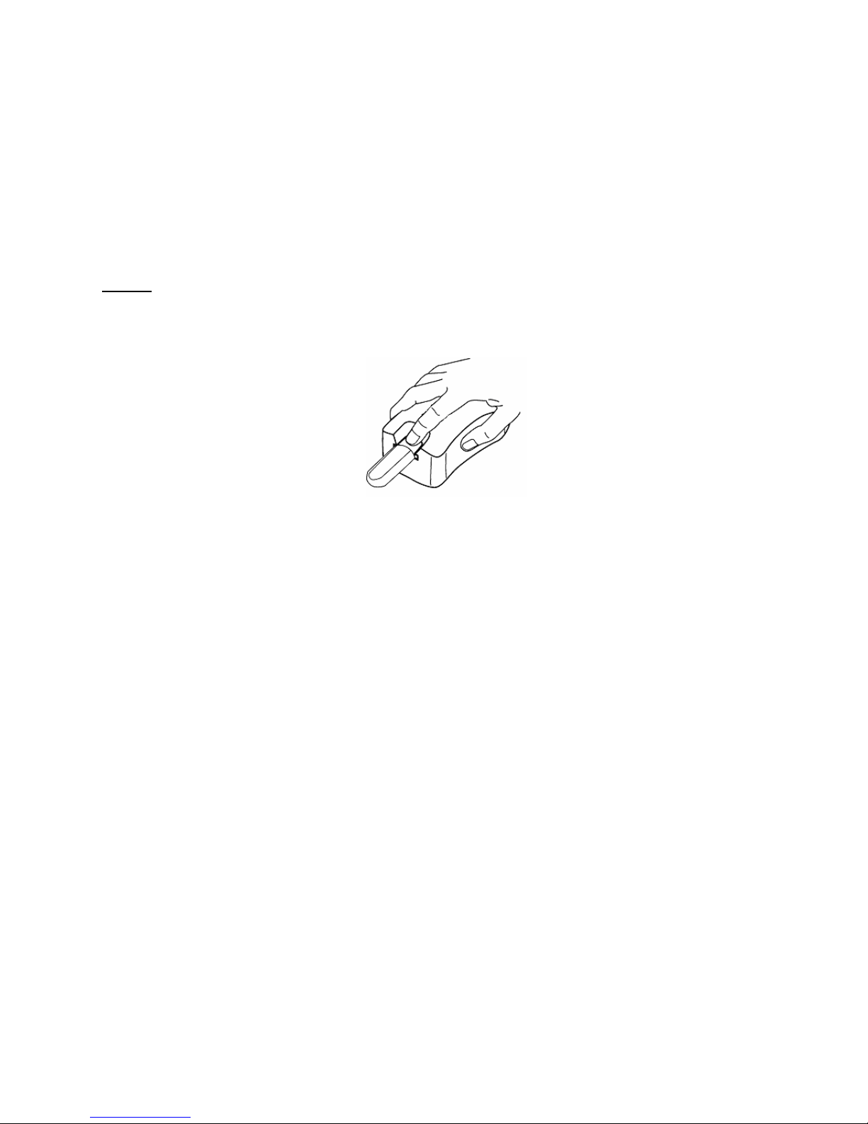
CAUTION: The movement of the FingerSimrelative to the oximeter sensor may cause erroneous pulse rate
and/or oxygen saturation readings. Use the FingerSimHolder to facilitate pulse generation
without introducing FingerSim™ movement relative to the oximeter sensor.
CAUTION: Do not use a FingerSimthat is cracked or leaking fluid.
CAUTION: Avoid extended exposure to sunlight.
CAUTION: The SpO2simulation by the FingerSimis temperature dependent. See Charts 6, 7 and 8 for the
appropriate adjustment. Allow at least one-hour stabilization at room temperature before using.
CAUTION: Do not store the FingerSimoutside the recommended Long Term Storage Temperature range
(32°F-104°F). NOTE: Temperatures outside this range for short duration are acceptable (for
example during shipping).
CAUTION: When testing flexible sensors, ensure the emitter and detector are vertically aligned on opposite
sides of the FingerSim.
CAUTION: Do not use beyond the calibration date.
CAUTION: No test system can simulate all possible operating conditions a pulse oximeter may encounter. Use
the FingerSimas an adjunct to other indications to determine proper pulse oximeter operation.
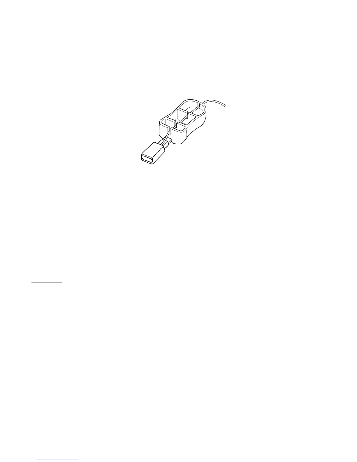
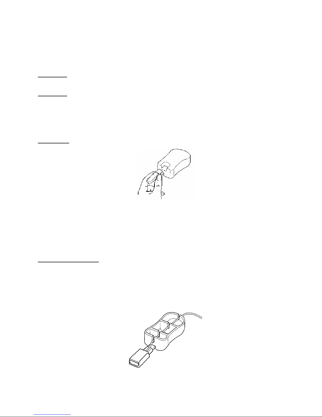
CAUTION: Improper insertion of the FingerSiminto the Holder can cause breakage. Insert the Phantom as
shown in Figure 7.
II. PURPOSE
The FingerSimPulse Oximeter Test System enables the healthcare professional to evaluate pulse oximeter and
sensor function at three simulated light absorption conditions. These absorption conditions are set to simulate a
typical finger at nominally 97%, 90%, and 80% SpO2levels. In addition, a pulse oximeter’s response to various
pulse amplitudes and rates can be simulated.
Before the availability of the BC Biomedical FingerSim, pulse oximetry systems (oximeter plus sensor) were not
easily tested. The oximeter’s measurement of the small pulsatile blood component and the interrelationship of the
oximeter calibration curve with the light emitting characteristics of the sensor made a true oximeter system tester
difficult to conceive. The BC Biomedical FingerSimSystem, when used as an adjunct to other indicators, aids
the healthcare professional in assessing performance of both oximeter and sensor.
CONTRAINDICATION: Do not use with reflectance or ear clip sensors. Use only with transmittance type,
finger or toe sensors.
CAUTION: No test system can simulate all possible operating conditions a pulse oximeter may encounter. Use
the FingerSimas an adjunct to other indicators to determine proper pulse oximeter operation.

4
III. DESCRIPTION
The BC Biomedical FingerSimsystem provides a rapid, inexpensive and convenient means of assessing the
function of the entire pulse oximeter system including the oximeter sensor. A set of three FingerSimsare
included in each kit. Each of the three FingerSimscontain a fluid with precisely controlled light absorption
characteristics sandwiched between two glass slides. The concentration of the substances in the three mixtures
allow the FingerSim™ to mimic the light absorbing qualities of arterial blood as measured by an oximeter at
different oxygen saturation values (nominally 97%, 90%, and 80%). The 97%, 90%, and 80% FingerSimsare
easily identified by the color coded end caps (Red - 97%, Blue - 90%, and Black - 80%).
Squeezing the colored coded flat end will produce a pulsatile movement of the solution. This pulsation is detected
as a pulse by the oximeter system being tested, and thus allows the oximeter to calculate and display an SpO2value
which corresponds to the fixed light absorbing characteristics of the particular FingerSimbeing used.
Figure 1. BC Biomedical FingerSim™
A holder is provided to stabilize the FingerSim™ while the pulsatile movement of the internal solution is generated.
Figure 2. BC Biomedical Replacement Holder

5
IV. THEORY OF OPERATION
The principle of differential light absorption is used by a pulse oximeter to determine the oxygen saturation of
arterial blood (SpO2). Red light and infrared light are differentially absorbed by oxygenated and deoxygenated
hemoglobin. The pulse oximeter has a sensor with light emitting diodes (LEDs) that provides these wavelengths of
light for transmittance through a measurement site, usually a finger. Based on the relative absorption of these two
wavelengths of light at the measurement site, the pulse oximeter determines the relative amount of oxygenated and
deoxygenated hemoglobin, which is calculated as SpO2.
In order to make this calculation independent of skin color, finger size, etc., the pulse oximeter uses only the time
varying light absorption component generated by the patient’s pulse. In addition, the pulse oximeter uses the period
of pulsation to measure the pulse rate.
The FingerSim™ absorbs light very much like a human finger. The overall red and infrared light absorption of the
FingerSim™ approximates the overall light absorption of a typical finger. In addition, the red and infrared photo
spectrometric light absorption of the inner solution approximates arterial blood as seen by the oximeter at 80%, 90%
and 97% oxygen saturation levels (see Figures 3, 4, and 5).
Minor SpO2variations will be seen between oximeter manufacturers because standards correlating red and infrared
light absorption to oxygen saturation in pulse oximetry are not available. Each manufacturer has developed its own
correlation and inevitably some differences have developed (see “Health Devices” June 1989). In addition, minor
SpO2variations between sensors will be observed due to the fact that red and infrared emitting light sources vary
slightly between sensors.
The FingerSim™ enables the healthcare professional to repeatedly test and evaluate the pulse oximeter system
(oximeter and sensor) under controlled light absorption conditions.
The time varying light absorption component required by a pulse oximeter is created in the FingerSim™ by
rhythmically pressing the color coded end. This creates a volume change in the distal (sensor) end of the
FingerSim™, analogous to the heart creating blood pressure waves that force blood into the finger. The amplitude
and rate of the pulse wave can be varied by changing the applied pressure and interval.

6
FingerSim LIQUID
(80% SpO2NOMINAL)
0.4
620 700 780 860 940
WAVELENGTH (nm)
ABSORB
ANCE
Figure 3. 80% SpO2Absorption Spectrum
Figure 4. 90% SpO2Absorption Spectrum
Figure 5. 97% SpO2Absorption Spectrum
FingerSim LIQUID
(90% SpO2NOMINAL)
0.4
620 720 820 920
WAVELENGTH (nm)
ABSORB
ANCE
FingerSim LIQUID
(97% SpO2NOMINAL)
0.4
620 720 820 920
WAVELENGTH (nm)
ABSORB
ANCE

7
V. CONDITIONS THAT AFFECT USE
A. Ambient Temperature
Ambient temperature changes will affect the light absorption characteristics of the FingerSim™, resulting in the
simulated SpO2value changing slightly with ambient temperature. Each FingerSim™ is calibrated at 72.5°F.
If the ambient temperature is between 67.5°F and 77.5°F no modification in the expected simulation is
necessary. However, if the ambient temperature is outside this range Figures 6, 7 and 8 should be used to
modify the expected simulated SpO2value. For example, if the 80% FingerSim™ was being used at 90°F
ambient temperature then the expected simulation would be increased to 83%.
74
75
76
77
78
79
80
81
82
83
84
85
86
40 45 50 55 60 65 70 75 80 85 90 95 100
Temperature °F
Simulated SpO2change with Ambient Temperature 80% FingerSim™
Figure 6. 80% SpO2Temperature Dependence
93
94
95
96
97
98
99
40 45 50 55 60 65 70 75 80 85 90 95 100
Temperature °F
Simulated SpO2change with Ambient Temperature 97% FingerSim™
Figure 8. 97% SpO2Temperature Dependence
84
85
86
87
88
89
90
91
92
93
94
95
40 45 50 55 60 65 70 75 80 85 90 95 100
Temperature °F
Simulated SpO2change with Ambient Temperature 90% FingerSim™
Figure 7. 90% SpO2Temperature Dependence

8
B. Movement Artifact
Analogous to the clinical environment, poorly attached sensors can result in movement between the oximeter
sensor and the FingerSim™ causing erroneous oximeter SpO2and Pulse Rate readings. Be sure to attach the
sensor to the FingerSim™ so that the emitting and detecting diode are vertically aligned and in direct contact
with the white transmissive surface about ¼” to ½” from the tip of the FingerSim™. Route the sensor cable in
such a way that it is not influencing the sensor attachment to the FingerSim™. For sensors with cables directed
to the back of the finger, route the cable through the notches in the bottom of the holder (see Figure 9).
Figure 9. Sensor Cable Routing Through Holder
C. Sensor Alignment and Position
The light absorption characteristics of the FingerSim™ are specified for light passing directly through the
FingerSim™. Be sure to vertically align the emitter and detector over the white transmissive surfaces about ¼”
to ½” from the tip of the FingerSim™. Misalignment or positioning on the black edges can cause erroneous
readings.
VI. CHECK OUT
Before each use, visually inspect each FingerSim™ carefully. Do not use the FingerSim™ if the calibration date
marked on the color coded handle has elapsed. Do not use the FingerSim™ if it is cracked and/or leaking fluid.
CAUTION: The SpO2simulation by the FingerSim™ is temperature dependent. See Charts 6, 7 and 8 for the
appropriate adjustment. Allow at least one hour stabilization at room temperature before using.

9
VII. OPERATING INSTRUCTIONS
A. Insert the FingerSim™ into the Holder
Carefully insert the short, flat, color coded end of the FingerSim™ into the slot provided at one end of the
FingerSim™ Holder. Grasp the sides of the color coded end and gently press the FingerSim™ into the Holder
until it reaches the stop of the holder (see Figure 10).
CAUTION: Improper insertion of the FingerSim™ into the Holder can cause breakage. Insert the
FingerSim™ as shown in Figure 10.
CAUTION: If the FingerSim™ is used without the recommended Holder, one must be very careful to
prevent movement between the sensor and the FingerSim™. Be sure no forces are applied to
the sensor or sensor cable (i.e. do not hold the sensor, or touch the sensor or cable) while
squeezing the color coded end of the FingerSim™ to generate the pulse signal. Motion
between the sensor and the FingerSim™ may cause erroneous SpO2and/or Pulse Rate
readings.
WARNING: FingerSim™ are fragile and must be handled with care, they contain glass.
Figure 10. Positioning the FingerSim™ in the Holder
B. Attach the Sensor
Attach the sensor under test to the FingerSim™ the same way you would to a patient’s finger. When testing a
finger clip sensor be certain the FingerSim™ is inserted all the way to the stop of the sensor. Position flex
sensors such that the emitter and detector are vertically aligned between ¼” and ½” from the tip of the
FingerSim™.
CONTRAINDICATION: Do not use with reflectance or ear clip sensors. Use only with transmittance type,
finger or toe sensors.
Route the cable in such a way that it does not influence the sensor under test. For sensors with cables directed to the
back of the finger, route the cable through the Holder in the notches on the bottom (see Figure 11).
Some oximeter systems may generate readings during sensor attachment due to the relative motion between the
FingerSim™ and the sensor. Allow 30 seconds for stabilization before going on to the next step.
Figure 11. Sensor Cable Routing Through Holder

10
C. Quiescent Test
After attaching the sensor allow the oximeter system under test about 30 seconds to stabilize. The oximeter
system should recognize this as a no pulse condition.
D. Oxygen Saturation Test
Gently press the FingerSim’s™ color coded end rhythmically keeping a minimum pressure on the FingerSim™
throughout the pulse cycle (see Figure 12). Generate the pulse by slightly increasing and decreasing the
pressure. Do not tap or move your finger away from the FingerSim™. This may create unwanted motion
artifact by rocking the FingerSim™. The oximeter system should recognize the simulated pulse and display a
pulse rate correlating to the input. The SpO2display should approximate the nominal value of the FingerSim™.
NOTE: Some slight variation in the SpO2readings between manufacturers is possible due to each
manufacturer’s interpretation of how the SpO2value relates to the absorption of the red and infrared
light in blood (see Theory of Operation).
Figure 12. Generating a Simulated Pulse
E. Pulse Rate Test
Vary the input pulse rate by rhythmically pressing the FingerSim™ colored coded end at fast and slow rates.
The pulse oximeter system should indicate high and low pulse rates. Verify that the pulse oximeter system
recognizes each pulse generated and that there are no extra pulses indicated by the oximeter.
F. Pulse Amplitude Test
The amplitude of the pulse waveforms being generated can be varied between 0% and 5% modulation levels by
changing the amount of pressure used to generate the pulse waveform. These amplitude changes should be
displayed by the oximeter on the perfusion indicator (various display techniques have been used by oximeter
manufacturers: colored coded L.E.D.s, L.E.D. bar graphs, L.C.D. waveforms, etc.).

11
VIII. SPECIFICATIONS
A. FingerSim™
Width .72”
Thickness .50”
Overall Infrared Light Absorption d.c.) 20dB to 40dB
Overall Red Light Absorption (d.c.) 20dB to 40dB
Operating Temperature Range 65°F to 90°F
Long Term Storage Temperature Range 32°F to 104°F
Typical infrared percent
modulation when squeezed 0 to 5 %
Red to Infrared Ratio (a.c.) @ 72.5°F and 660nm/910nm:
80% FingerSim™ - 1.065 to 1.100
90% FingerSim™ - 0.765 to 0.800
97% FingerSim™ - 0.573 to 0.598
B. Holder
Width 2.4”
Length 4.3”
Height 1.6”

12
IX. SERVICE AND MAINTENANCE
There is no service or maintenance possible with the FingerSim™ test systems. Each FingerSim™ is dated to
identify its useful life. Replace any FingerSim™ that shows signs of leakage.
To clean FingerSim™ wipe with isopropyl alcohol.
X. WARRANTY
BC GROUP INTERNATIONAL, INC. (BC Biomedical) warrants to the purchaser that each FingerSim™ shall be
free of defects in materials and workmanship such that each system when properly used shall perform to
specifications supplied within this manual until the calibration date marked on the FingerSim™ has elapsed. Note:
This warranty specifically excludes any internal glass breakage. BC Biomedical shall replace all FingerSims™ or
accessories found to be defective in accordance with this warranty, free of charge, for which BC Biomedical has
been notified by the purchaser that there is a defect, provided said notification occurs within the applicable warranty
period (i.e. before the calibration date). This warranty shall be the sole and exclusive remedy by the purchaser
hereunder for any FingerSims™ or accessories delivered to the purchaser which are found to be defective in any
manner whether such remedies be in contract, tort or by law.
The FingerSim™ contains a substance prepared to very exact proportion and are assembled under precise
specifications. They are not repairable and must be replaced at the first sign of deterioration or damage. Any sign
of tampering or any kind of misuse or abuse shall void the warranty in its entirety.
DISCLAIMER/EXCLUSIVITY OF WARRANTY. THE EXPRESS WARRANTIES SET FORTH IN THIS
MANUAL (SECTION X) ARE EXCLUSIVE AND NO OTHER WARRANTIES OF ANY KIND,
WHETHER STATUTORY, WRITTEN, ORAL, OR IMPLIED INCLUDING WARRANTIES OF FITNESS
FOR A PARTICULAR PURPOSE OR MERCHANTABILITY SHALL APPLY.
XI. ACCESSORIES
The following accessories function with the FingerSim™ Oximeter Testing System:
FingerSim™ Replacement Set
Includes a set of three FingerSim™, 97%, 90% and 80% SpO2(Nominal).
Replacement Holder
FingerSim™ Holder

13
XII. TROUBLE SHOOTING CHART
Before calling Customer Support, please check the following chart for a possible solution to the problem you are
experiencing.
SYMPTOMS
POSSIBLE
CAUSE
POSSIBLE
SOLUTION
• Oximeter measures slightly
different SpO2values than the
nominal FingerSim™ value.
• Expected variation due to
manufacturing tolerances.
• Verify that minor variations
in SpO2are not clinically
significant.
• Oximeter measures high or
low SpO2bias compared to
the nominal FingerSim™
value.
• FingerSim™ is not at room
temperature.
• Allow at least 1 hour
stabilization at room
temperature .
• Room temperature not at 72.5° F. • Adjust expected SpO2value
(see Charts 6, 7, and 8).
• Cracked or leaking FingerSim™. • Replace FingerSim™.
• Outside calibration date. • Replace FingerSim™.
• Improper sensor attachment to the
FingerSim™.
• Ensure the sensor is
attached to the FingerSim™
per section VIII(B).
• Damaged Sensor • Try another sensor.
• Damaged Oximeter • Try another oximeter.
• Oximeter displays erratic
SpO2values.
• Motion of the sensor relative to the
FingerSim™.
• Use holder provided. Route
cable per VII(B). Be certain
sensor is seated properly on
FingerSim™.
• Damaged Sensor • Try another sensor.
• Damaged Oximeter • Try another oximeter.
• No pulse when the
FingerSim™ is squeezed.
• Cracked or leaking FingerSim™. • Replace FingerSim™.
• Damaged Sensor • Try another sensor.
• Damaged Oximeter • Try another oximeter.
For further information contact:
BC Biomedical
BC Group International, Inc.
9415 Gentry Ave.
St. Louis, MO 63125
314-638-3800
800-242-8428
314-638-3200 FAX
March 20, 2003
This manual suits for next models
1
Table of contents
Other BC Biomedical Medical Equipment manuals

BC Biomedical
BC Biomedical MAXISIM 2000 User manual

BC Biomedical
BC Biomedical PLA User manual

BC Biomedical
BC Biomedical ESU-2000 Series Guide User manual

BC Biomedical
BC Biomedical NIBP-1010 User manual

BC Biomedical
BC Biomedical PS-2105 User manual

BC Biomedical
BC Biomedical Auxiliary ESU Load Resistor User manual

BC Biomedical
BC Biomedical PS-2200 series User manual

BC Biomedical
BC Biomedical PS-2110 User manual

BC Biomedical
BC Biomedical ENDOCHECK Test system User manual