BC Biomedical ULT-2000 series User manual

ULTRASOUND TRANSDUCER
LEAKAGE TESTER
ULT-2000 SERIES
USER MANUAL


1
WARNINGS ................................................................................................................ 2
DESCRIPTION ............................................................................................................ 6
OVERVIEW.................................................................................................................. 9
KEYS............................................................................................................................ 10
SCREENS ................................................................................................................... 12
SETUP ......................................................................................................................... 17
OPERATIONS ............................................................................................................. 21
MANUAL REVISIONS.................................................................................................. 26
WARRANTY................................................................................................................. 26
SPECIFICATIONS ....................................................................................................... 27
NOTES......................................................................................................................... 28
BC BIOMEDICAL
ULT-2000 SERIES
TABLE OF CONTENTS

2
WARNING - USERS
The ULT-2000 Testers are for use by
skilled technical personnel only.
WARNING - USE
The ULT-2000 Testers are intended for testing
only and they should never be used in
diagnostics, treatment or any other capacity
where they would come in contact with a patient.
WARNING - CONNECTIONS
All connections to patients must be removed
before connecting the Device Under Test (DUT)
to the Tester. A serious hazard may occur
if the patient is connected when
testing with the Tester.
Do not connect any leads from the patient
directly to the Tester or DUT.
WARNING – POWER ADAPTOR
Unplug the Power Adaptor before
cleaning the surface of the Tester.
WARNING - LIQUIDS
Do not submerge or spill liquids on the Tester.
Do not operate the Tester if internal components
not intended for use with fluids may have been
exposed to fluid, as the internal leakage may
have caused corrosion and be a potential hazard.
WARNING - MODIFICATIONS
The ULT-2000 Testers are intended for use within
the published specifications. Any application
beyond these specifications or any unauthorized
user modifications may result in hazards or
improper operation.

3
WARNING
High Voltages are generated when running
electrical leakage tests.
Do not touch any surface that is in contact with
the Tester, including the ultrasound transducer
and the adapter.
Do not touch the liquid in the test basin, as it is
at an electrical potential that is equal to the
“challenge” voltage being used to perform the
electrical safety test.
CAUTION - SERVICE
The ULT-2000 Testers are intended to be
serviced only by authorized service personnel.
Troubleshooting and service procedures
should only be performed by
qualified technical personnel.
CAUTION - ENVIRONMENT
The ULT-2000 Testers are intended to function
between 15 and 30 °C.
Exposure to temperatures outside this range can
adversely affect the performance of the Tester.
CAUTION - CLEANING
Do not immerse. The Tester should be cleaned
by wiping gently with a damp, lint-free cloth.
A mild detergent can be used if desired.
CAUTION - INSPECTION
The ULT-2000 Testers should be
inspected before each use for wear and
the Tester should be serviced
if any parts are in question.
4
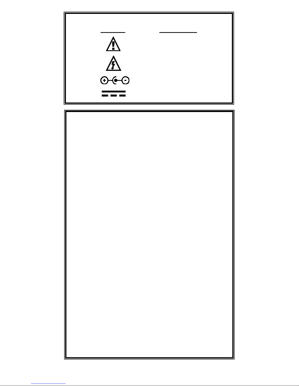
NOTICE – SYMBOLS
Symbol Description
Caution
(Consult Manual for Further Information)
Electrical Caution
(Consult Manual for Further Information)
Center Negative
Direct Current
NOTICE – ABBREVIATIONS
Amps Ampheres
c centi- (10-2)
C Celsius
CF Crest Factor
° degree
DFA Digital Fast Acquisition
DUT Device Under Test
hrs hours
Hz hertz
k kilo- (103)
kg kilograms
kHz kilohertz
lbs pounds
L1, L2, L3 Location 1, 2, 3
M Mega- (106)
MHz Megahertz
µ micro- (10-6)
µA microampere
m milli- (10-3)
mA milliampere
mHz millihertz
mm millimeter
ms millisecond
mV millivolts
Ωohm
PC Personal Computer
Pk peak
RF Radio Frequency
RMS Root Mean Square
US United States
V volt

5
Manual ULT-2000 Series Copyright © 2007
www.bcgroupintl.com Made in the USA
11/07 Rev04
NOTICE – DISCLAIMER
BC GROUP INTERNATIONAL, INC. RESERVES THE RIGHT TO
MAKE CHANGES TO ITS PRODUCTS OR SPECIFICATIONS AT
ANY TIME, WITHOUT NOTICE, IN ORDER TO IMPROVE THE
DESIGN OR PERFORMANCE AND TO SUPPLY THE BEST
POSSIBLE PRODUCT. THE INFORMATION IN THIS MANUAL HAS
BEEN CAREFULLY CHECKED AND IS BELIEVED TO BE
ACCURATE. HOWEVER, NO RESPONSIBILITY
IS ASSUMED FOR INACCURACIES.
NOTICE – CONTACT INFORMATION
BC BIOMEDICAL
BC GROUP INTERNATIONAL, INC.
PO BOX 25125
9415 GENTRY AVE
ST. LOUIS, MO 63125
USA
1-800-242-8428
314-638-3800
www.bcgroupintl.com
NOTICE – DISCLAIMER
USER ASSUMES FULL RESPONISIBILITY FOR UNAUTHORIZED
EQUIPMENT MODIFICATIONS OR APPLICATION OF EQUIPMENT
OUTSIDE OF THE PUBLISHED INTENDED USE AND
SPECIFICATIONS. SUCH MODIFICATIONS OR APPLICATIONS
MAY RESULT IN EQUIPMENT DAMAGE OR PERSONAL INJURY.

6
The Model ULT-2000 Series is a family of Microprocessor based, Ultrasound Transducer
Leakage Testers. The ULT-2010 measures both the conductivity of the cleaning medium
and the leakage current of the ultrasound transducer. The ULT-2020 offers a Meter mode
and a Datalog.
The following are highlights of some of the main features:
ULT-2010 (BASIC FEATURES):
• LARGE GRAPHICS DISPLAY WITH CURSOR SELECTION
OF OPTIONS AND SETUP OF PARAMETERS
• USER-SELECTABLE CHALLENGE (TEST) VOLTAGE
(90 TO 275 VAC)
• USER SELECTABLE CHALLENGE (TEST) FREQUENCY
(50 OR 60 HZ)
• USER-SELECTABLE TEST LIMITS BY ULTRASOUND TRANSDUCER
MANUFACTURER AND MODEL
• 1% FS MEASUREMENT ACCURACY
• AUTO RANGING WITH 10, 250, OR 500 µA FS
• AUTOMATIC INTERNAL SELF TEST
• SINGLE BUTTON PRESS FOR FULL SYSTEM TEST
• SIMPLE GO-NOGO MODE – FOR NON-TECHNICAL USERS
• ANALYTICAL MODE – FOR TECHNICAL USERS
• DIGITAL CALIBRATION – NO POTS TO TURN
• USER-SELECTABLE DISPLAY OPTIONS
• BATTERY LIFE DISPLAY (0 to 100%)
• PROGRAMMABLE BACKLIGHT TIMER
• CONTRAST IS SOFTWARE ADJUSTABLE
• FLASH UPGRADEABLE FIRMWARE
• RS232 & PC SOFTWARE
• SERIAL PRINTER OUTPUT WITH PROGRAMMABLE USER HEADER
• REAL TIME CLOCK
• COMPATIBLE WITH DALE®TECHNOLOGY DALE800®AND FLUKE®
BIOMEDICAL ULT-800®ULTRASOUND TRANSDUCER ADAPTERS AND
DUAL CONDUCTIVITY PROBES
BC BIOMEDICAL
ULT-2000 SERIES
ULTRASOUND TRANSDUCER LEAKAGE TESTER

7
ULT-2020 (METER, DATALOG)
HAS ALL THE BASIC MODEL FEATURES PLUS:
• METER MODE FOR EXTENDED MEASUREMENT PERIODS
• PROGRAMMABLE METER CHALLENGE VOLTAGE AND FREQUENCY
• PROGRAMMABLE METER TIMER
• DATALOG WITH STORAGE OF 99 TEST RECORDS
OPTIONAL ACCESSORIES:
BC20 - 21103 BATTERY ELIMINATOR (US Version)
BC20 - 21101 BATTERY ELIMINATOR (Euro Version)
BC20 - 41337 RS232 COMMUNICATIONS CABLE (7 Pin Mini-Din to DB 9 F)
BC20 - 41339 COMMUNICATION CABLE ADAPTER (USB to DB9 M)
(For use with BC20-41337)
BC20 - 30106 BC BIOMEDICAL SMALL SOFT SIDED CARRYING CASE
ULT-PC-10 DUAL CONDUCTIVITY PROBE (Short)
ULT-PC-20 DUAL CONDUCTIVITY PROBE (Long)
BC20 - 42200 CIDEX® COMPATIBILITY TRAY
BC20 - 42300 EXTERNAL PRINTER
BC20 - 42310 PACKAGE OF 5 ROLLS OF PAPER FOR BC20 – 42300

8
ULTRASOUND TRANSDUCER ADAPTERS:
ULT-PA-11 SONOSITE TEE TRANSDUCER ADAPTER
(For use with all Sonosite transducers – including Tee)
ULT-PA-10 ULTRASOUND TRANSDUCER ADAPTER – ACUSON
(For use with Acuson/Siemens 8v5, 15l8w, v5m, 3v2c
transducers)
ULT-PA-12 ULTRASOUND TRANSDUCER ADAPTER – ACUSON
(For use with Acuson/Siemens 260-pin transducers)
ULT-PA-13 ULTRASOUND TRANSDUCER ADAPTER – ACUSON
(For use with Acuson/Siemens 156-pin and v510b transducers, as
well as, ATL UM4, UM9 and ATL 5MHz bi plane)
ULT-PA-14 ULTRASOUND TRANSDUCER ADAPTER – ATL/PHILIPS
(For use with ATL C9-5 curved array; ATL l7-4 linear array; ATL
UM9HDI; ATL HDJ 3000, 3500, 5000; ATL MPT74)
ULT-PA-15 ULTRASOUND TRANSDUCER ADAPTER – GE LOGIQ
(For use with GE Logiq transducers 3, 5, 7, 9 and GE Vivid
transducers 3, 5, 7, 6T, 9T)
ULT-PA-16 ULTRASOUND TRANSDUCER ADAPTER – GE LOGIQ
(For use with GE Logiq and GE P9603AU transducers)
ULT-PA-17 ULTRASOUND TRANSDUCER ADAPTER – PHILIPS
(For use with Ie33/iU22)
ULT-PA-18 ULTRASOUND TRANSDUCER ADAPTER – PHILIPS/HP
(For use with Philips/HP 4500 and Sonos 5500/7500 transducers)
For compatibility with specific manufacturer and model ultrasound transducers, please contact
BC Group International and request the most recent copy of the ULT-2000 Ultrasound
Transducer and Adapter Compatibility chart. There may be additional adapters available that
are not on the above list. The above list is accurate as of the date of this User Manual revision.
9
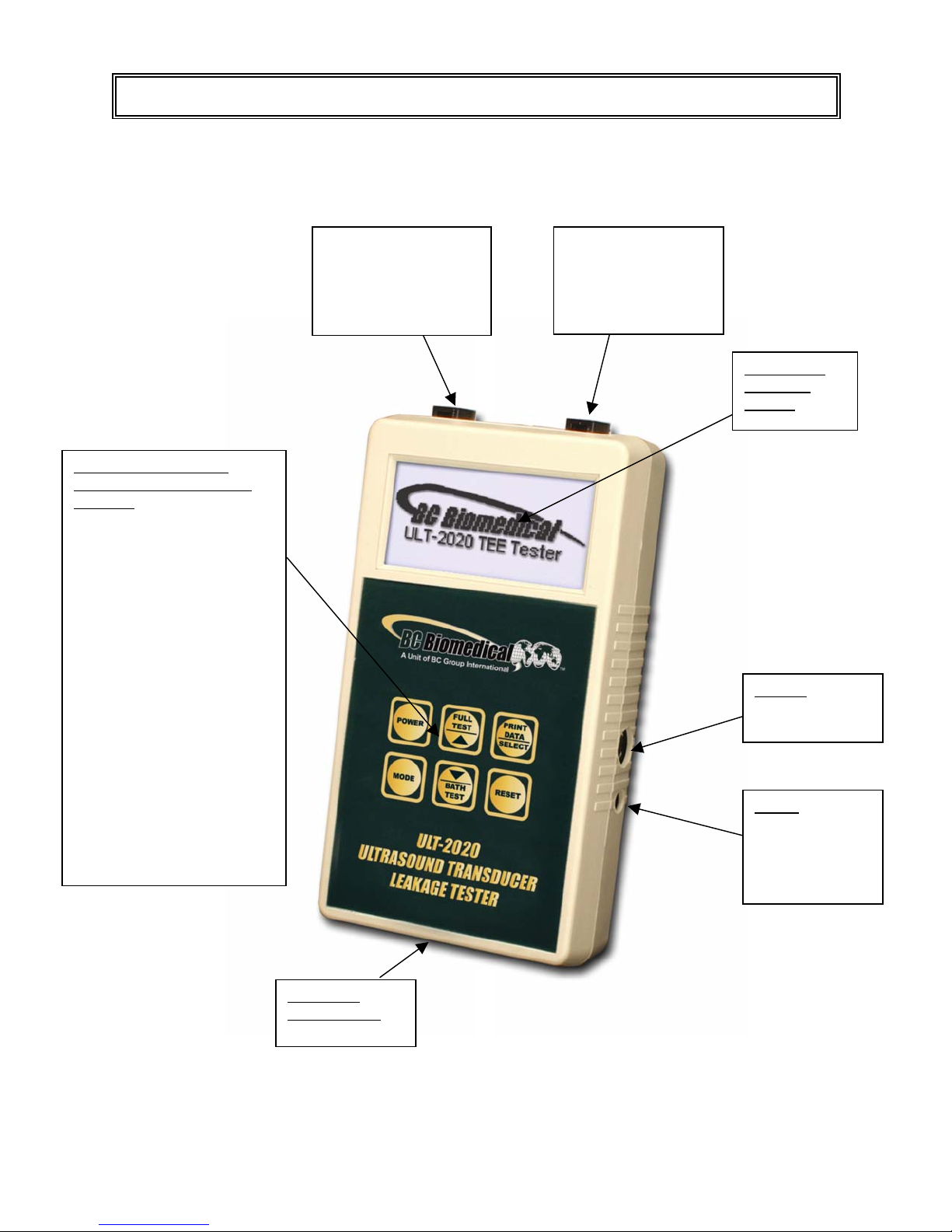
This section looks at the physical layout of the ULT-2000 Series and gives descriptions of
the elements that are present.
Locking DUT
connector – to
ultrasound
transducer via
transducer adapter
RS232:
7 PIN Mini-Din
(Optional)
Power
2.1 mm Jack
(Optional Battery
Eliminator)
6 Light Touch Keys for
Selecting Parameters and
Settings:
POWER for Turning Unit On
and Off
FULL TEST / UP for Testing
both Conductivity and
Leakage and for Scrolling
Through Selected Options
SELECT/PRINT for
Selecting Next Available
Parameter and Printing
MODE for Changing
Operating mode and
Entering/Exiting Setup Mode
BATH ONLY / DOWN for
Testing Conductivity and for
Scrolling Through Selected
Options
RESET for Canceling Test or
for Returning to Main Screen
after Test
9V Battery
Compartment
(Back)
Backlit LCD
Graphical
Display
Locking Device Under
Test (DUT) connector
– to conductive bath
via Dual Conductivity
Probe
OVERVIEW
10
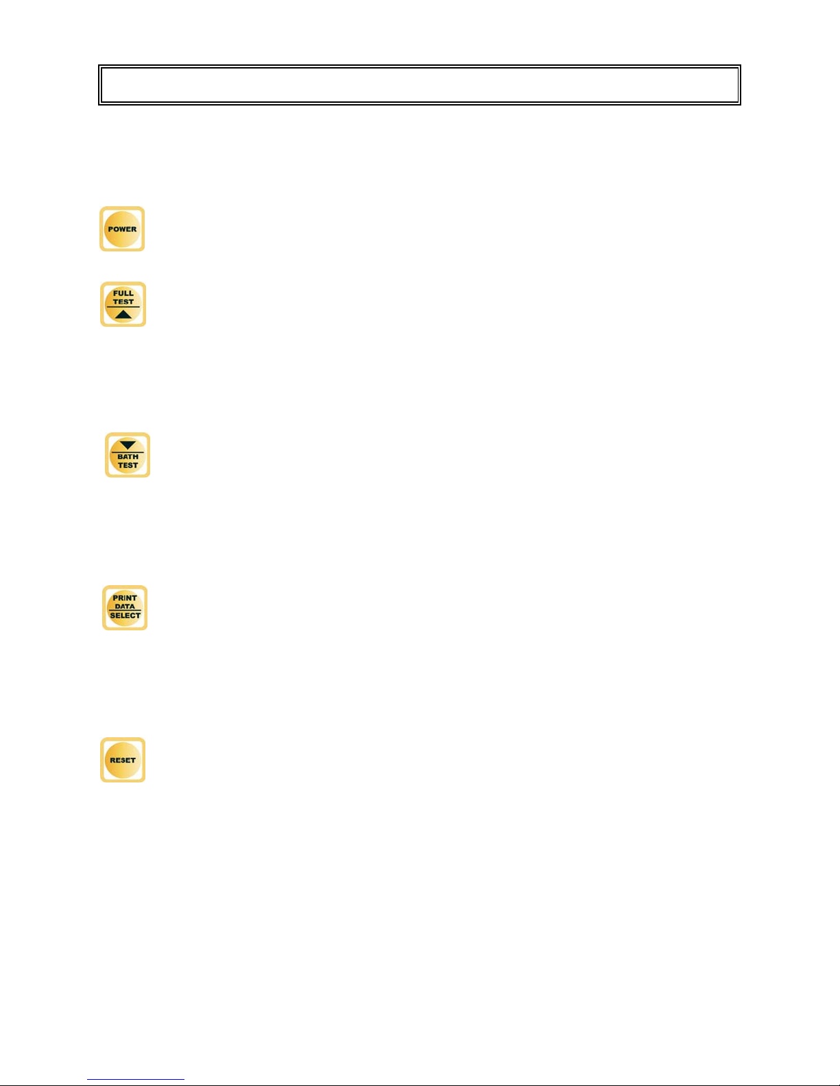
Six tactile-touch keys with audio feedback are provided for system operation:
– This key turns the unit off and on. The unit will initiate with the Main Screen .
– When not in SETUP mode, this key will initiate the Full System Test, which
includes both a bath conductivity test and a transducer electrical leakage test.
When in the SETUP mode, this key will scroll up through the available settings.
– When not in SETUP mode, this key will initiate a conductivity test of the
conductive liquid medium in the bath. When in the SETUP mode, this key will
scroll down through the available settings.
– When not in the SETUP mode, this key will print the latest test results to the
serial port. When in the SETUP mode, this key will select the next available
parameter.
– When not in SETUP mode, this key is used to Reset the system to the main
screen.
KEYS

11
– This key toggles the unit into and out of the system modes. Depressing this key
will toggle from the Main screen to the Meter Screen (ULT-2020 Only) and then
to the Datalog Screen (ULT-2020 only).
Depressing and holding this key will allow entry to the SETUP mode where the
configuration can be viewed and adjusted. When in the SETUP mode, this key
will exit the SETUP mode and return to the previously viewed screen. This will
also save the system settings to the internal EEPROM memory so they will be
retained even with the power turned off or battery removed

12
MAIN SCREEN – The main screen indicates to the user that the ULT-2000 Series unit is
initialized and ready for testing. This screen is loaded after power-up initialization and can
be shown by pressing the key after a test is complete.
FULL TEST SCREEN – This screen is accessed by pressing the button. The
FULL TEST consists of a Self Test, Bath Conductivity Test and a Probe Leakage Test. The
Self Test ensures that the ULT-2000 is working properly before checking the Device Under
Test (DUT). The Bath Conductivity Test ensures that the test fluid has proper conductivity.
The Probe Leakage Test measures the leakage current of the DUT.
DUT Information
Manufacturer: Model
(Optional, see SETUP
Section for more
details.)
Progress Indicator
Test Measurements
(Optional, see SETUP
Section for more details.)
Test Procedure:
SOURCE TEST to verify voltage
used during test.
CIRCUIT TEST to verify
measurement circuitry.
BATH CONDUCTIVITY TEST to
validate cleaning solution.
PROBE LEAKAGE TEST to
measure the leakage current of
the DUT.
SCREENS
13
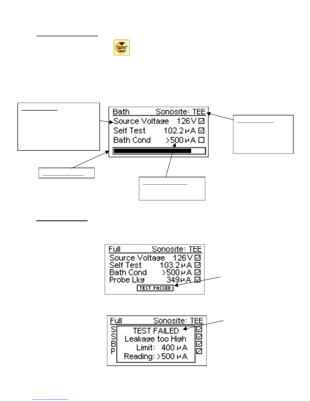
BATH ONLY SCREEN – This mode is used when preparing the bath solution. This screen
is accessed by pressing the button. The BATH TEST consists of a Self-Test and a
Bath Conductivity Test. The Self Test ensures that the ULT-2000 Series unit is working
properly before checking the DUT. The Bath Conductivity test ensures that the test fluid
has the proper level of electrical conductivity needed for a good electrical leakage test.
TEST MESSAGES – If a test passes, the progress bar indicator will change to indicate that
the DUT passed the limits selected in the SETUP menu.
If a test fails, the screen will change to indicate what portion of the test failed.
Test Procedure:
SOURCE TEST to verify voltage
used during test.
CIRCUIT TEST to verify
measurement circuitry
BATH CONDUCTIVITY TEST to
validate cleaning solution.
DUT Information
Manufacturer: Model
(Optional, see SETUP
Section for more
details.)
Progress Indicator
Test Measurements
(Optional, see SETUP
Section for more details.)

14
METER SCREEN (ULT-2020 ONLY) – The meter screen allows for extended leakage
current measurements. This helps in troubleshooting ultrasound probes. This screen is
accessed by pressing the key. The test voltage, frequency, and output control
are selected by pressing the key.
Source Voltage
Selectable from 90
to 275 VAC
Source Frequency
Selectable 50/60 Hz
Output Control
Off
ON
30 Seconds
60 Seconds
90 Seconds
2 Minutes
5 Minutes
10 Minutes
15 Minutes
30 Minutes
15
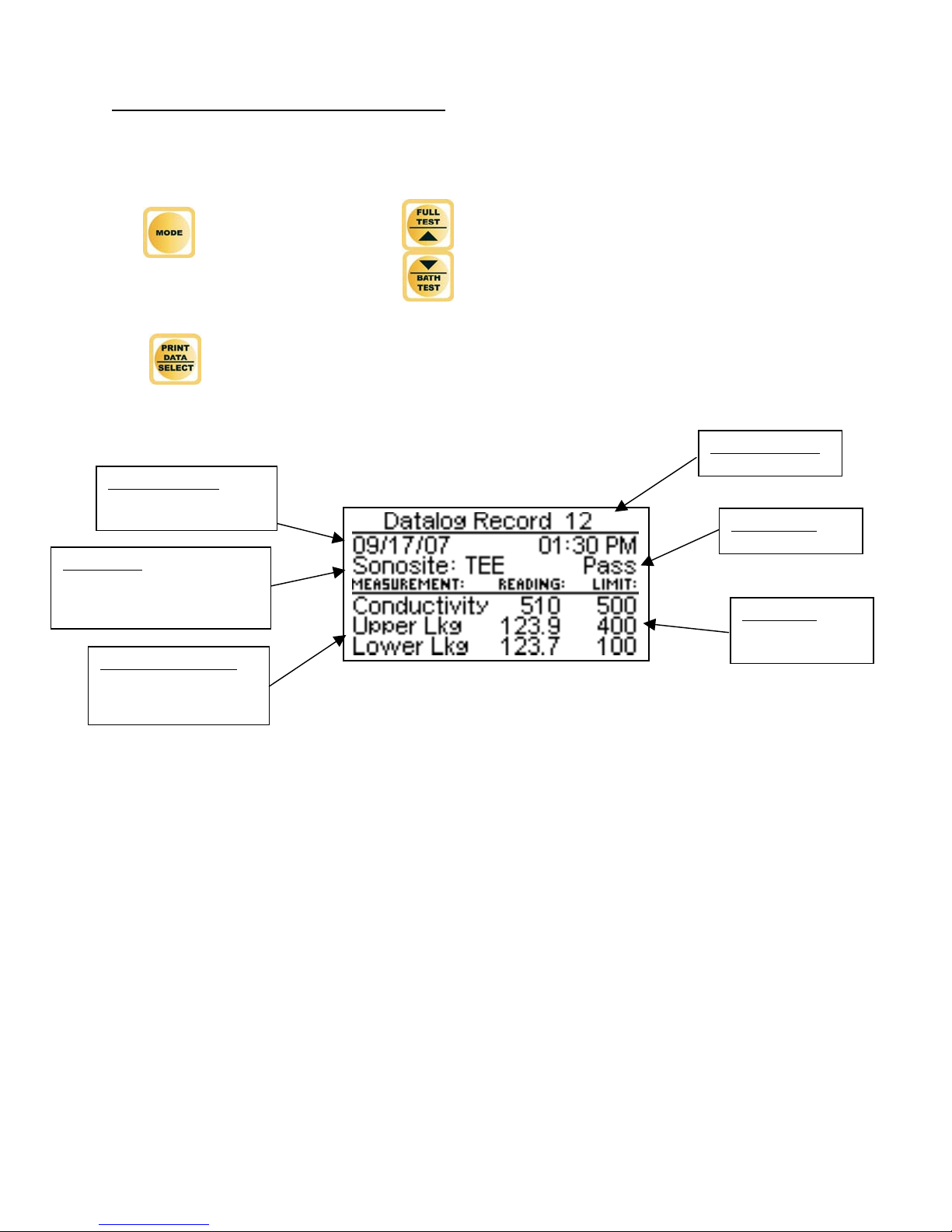
DATALOG SCREEN (ULT-2020 ONLY) – The Datalog screen shows the test results
for up to 99 test records. The datalog includes a Time/Date Stamp, the Test Type,
Pass/Fail, Test Measurements, and Test Limits. This screen is accessed by pressing
the key. In this screen, the arrows are used to scroll through the test
records.
The key is used to print the displayed record to the serial printer.
Record Number
(
1-99
)
Test Results
Pass/Fail
Test Limits
Pass/Faill Test
Limits1-500
µ
A
Test Timestamp
Date and Time test
was run.
Probe Type
Probe Manufacturer and
Model. Blank if Fixed or
User Test Limits.
Test Measurements
Measurements taken
during test.

16
LOW BATTERY – When the battery life reaches 10 percent, the LOW BATTERY
message box will be displayed.
BATTERY ELIMINATOR – A 2.1 mm jack is provided for the optional 9 VDC Battery
Eliminator (BC20-21100, BC20-21101) that may be used for continuous run applications. It
bypasses the internal battery when plugged in.
NOTE: The unit is shipped with the battery installed. To ensure that the battery is fresh
when received, there is a red plug in the Power Input jack. This plug must be removed
before use.
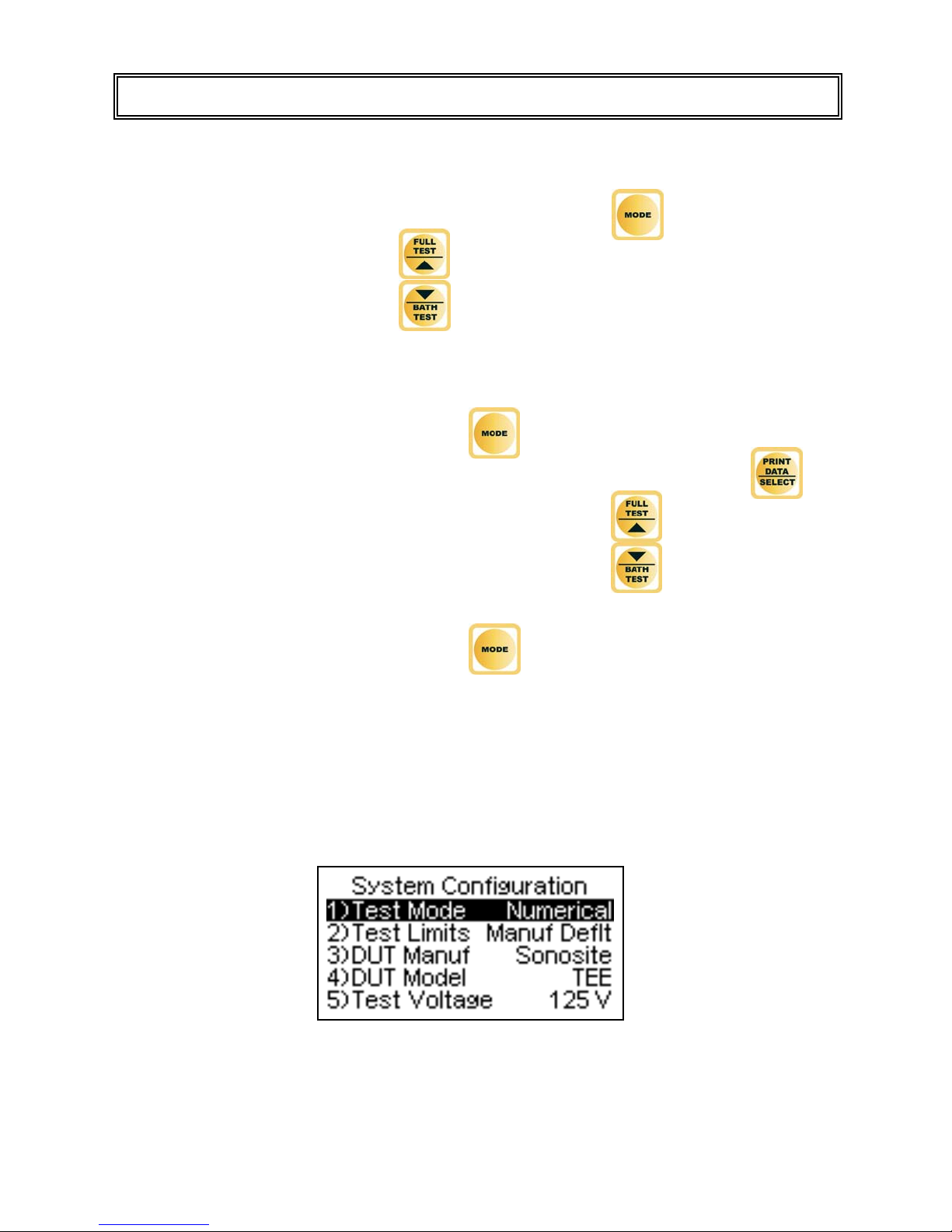
17
The SETUP Mode allows the user to adjust the configuration of the meter. The Setup
screen can be entered by depressing and holding using the key until the Access
code screen appears (5 sec). The arrows are then used to enter the access code.
When the access code is displayed, the key is then depressed again to gain
access to the SETUP mode. The parameters can be changed by using the key
to scroll down through the list and highlight the line and the arrows to toggle the
available options.
The Setup screen can be exited using the key.
The following is a typical screen for the System Configuration and a table of the available
setting options with a brief description of each Parameter.
SETUP

18
System Setup Configuration
Parameter Description Range
Test Mode
Determines whether the test measurements (actual test
readings) are shown in the test screen, or if the unit will
simply give a PASS or FAIL result. The Default setting
is Numerical.
PASS/FAIL or
Numerical
Test Limits
Determines the settings for the test limits. Fixed limits
are set by the factory and cannot be adjusted. User
limits are programmed by the User through a special
access code. Manufacturer Default limits are suggested
test settings by probe manufacturer and model. Custom
limits are a set of settings by probe manufacturer and
model programmed by the user with a PC configuration
program.
Fixed, User, Manuf
Deflt, or
Custom
DUT Manuf
Selects the DUT manufacturer.
NOTE: Only available when Test Limits is set to
Manufacturer Default or Custom.
User Defined
DUT Model
Selects the DUT Model.
NOTE: Only available when Test Limits is set to
Manufacturer Default or Custom.
User Defined
Test Voltage
Displays the source “challenge” voltage to be used
during the Test. The Fixed setting is 120 volts, as
normally used in North America.
90-275 VAC
(Read Only)
Frequency
Displays the Frequency of the source “challenge”
voltage. The Fixed setting is 60 Hz, as set for use in
North America.
50 or 60 Hz
(Read Only)
Cond Limit
Displays the test limit for Bath Conductivity Test.
The measured leakage must be higher than this value to
pass and confirm that the Bath Solution is a valid media
for the Leakage Test. This setting is for display only and
cannot be modified.
500 µA
(Read Only)
Lkg Upper Limit
Displays the upper test limit for Transducer Leakage
Current Test. The measured Leakage Current must be
lower than this value to pass. The Fixed setting is 100
µA
1-500 µA
(Read Only)
Lkg Lower Limit
Displays the lower test limit for Transducer Leakage
Current Test. The measured Leakage Current must be
higher than this value to pass. The Fixed setting is 40
µA
1-500 µA
(Read Only)
Setup Clock
Pressing the Up arrow while this parameter is selected
displays the Clock Configuration screen where the Date
and Time are configured.
Press UP
Clear Datalog
Pressing the Up arrow while this parameter is selected
will erase the test records stored in the Datalog (ULT-
2020 Only)
Press UP
Battery Life Displays current life of the battery.
At 10%, a warning screen will appear.
0-100%
(Read Only)
Contrast Adjust Sets the contrast of the display screen.
The Default setting is 15. 0-20
Backlight (Sec)
Off – Always off
1-30 sec – The elapsed time after which the backlight
will automatically turn off.
ON – Always ON.
The Default setting is 30 seconds.
Off, 1-30 sec, ON
Other manuals for ULT-2000 series
2
Table of contents
Other BC Biomedical Test Equipment manuals


